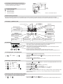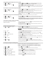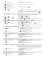
1
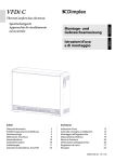
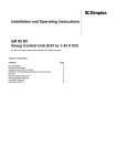
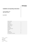
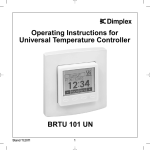
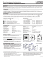
Mounting and operating instructions RTWU 301 UN Room Temperature Controller 459238.66.54 12/06/F Room temperature controller with week cycle clock, floor temperature thermostat and floor temperature sensor integrated in a flush mounted switch installation frame. IMPORTANT! This device complies with the following standards: EN 60730-1, EN 50082-1 and EN 61000 and may, in compliance with the pertinent VDE safety regulations (German regulations for electrics) and the rules and prescriptions established by the local power supply companies currently operative and in force, be installed by an expert electrician only. 1. Application The specially has been specially devised for use within the limits of technological building applications. It suits especially for the control of temperatures produced by floor heating- and floor temperature equalization systems and is mounted in an UP box. It can either be mounted as an independent device or be mounted flush using DIN 49075 compliant intermediate frames which allow adaptation to almost all currently available flush switch installation frames. 2. Functioning Based on the data sensed by an integrated sensor, the controller measures the existing room temperature. As long as the maximum admissible floor indicates that temperature is not transcended, the heating contact is, upon the lower deviation of the room temperature set value, closed. The signal the heating phase is active. The operation of the digital week cycle clock is based on three different programs that enable to change over from comfort temperature to temperature decrease mode. The controller is delivered preset to „normal“ day sequences, see section 20, “Factory settings”. All settings are stored permanently. Actuating the reset key enables to reset to the factory settings. Actuating the touch key enables to select the following operating modes: Frost antifreezing mode active, approx. 7°C Night temperature decrease mode (permanent) Day comfort temperature mode (permanent) Clock clock-controlled change-over between comfort and temperature decrease mode In adjusting mode (see section 19), the individual functions can be adapted as follows: J1 Indication: set value / clock time alternately, set value, clock time (factory setting) (factory setting = 30°C) J2 Max. set temperature . . . . . . . . . . 6 ... 30° C J3 Max. set temperature . . . . . . . . . . 5 ... 29° C (factory setting = 5°C) (factory setting = 0 K) J4 Temperature correction . . . . . . . – 9 ... +8 K J5 Max. floor temperature . . . . . . . . 20 ... 60° C (factory setting = 50°C (factory setting = 6 A) J6 Load current correction . . . . . . . 1 ... 10 A J7 Self-learning function. . . . . . . . . . 0 /1 (factory setting = 1 = activated) 3. Technical data Operating voltage: . . . . . . . . . . . . . . . Range of control: . . . . . . . . . . . . . . . . Display range: . . . . . . . . . . . . . . . . . . . . Temperature setting: . . . . . . . . . . . . Sensor tolerance: . . . . . . . . . . . . . . . . Switching difference: . . . . . . . . . . . . . Power consumption: . . . . . . . . . . . . . Temperature decrease: . . . . . . . . . . Heating contact: . . . . . . . . . . . . . . . . . . Internal sensor: . . . . . . . . . . . . . . . . . . External sensor:. . . . . . . . . . . . . . . . . . 230 V / 50 Hz 5 … 30° C 0 … 40° C in 0.5 K steps ± 0.5 K approx. 1 K approx. 1.5 VA adjustable (factory setting: 4 K) make contact, max. 230 V, 10 (2) A NTC, 47 K NTC, 2 K Indications: . . . . . . . . . . . . . . . . . . . . . . . . . Electrical connections: . . . . . . . . . . . . . Degree of protection: . . . . . . . . . . . . . . Protection class after corresponding installation: . . . . . . . . . Mounting: . . . . . . . . . . . . . . . . . . . . . . . . . . Ambient temperature: . . . . . . . . . . . . . . Storage temperature: . . . . . . . . . . . . . . Radio interference suppression: . . . Power reserve: . . . . . . . . . . . . . . . . . . . . . Adjusting options: . . . . . . . . . . . . . . . . . . LCD display screw terminals (1.5 … 2.5 mm2) IP 30 II in 쏗 55 UP box 0 … 30° C – 20 … + 70° C acc. to EN 50081-1, EN 50082-1 4 days (after 1 service hour) see section 2, adjusting mode 4. Scope of delivery The controller is delivered complete with switch frame cover. 5. Opening of the controller housing Caution: To remove the housing cover (1) by pulling it off, make sure to hold the switch frame (3) at both sides, top and bottom! Use a screw driver to remove the housing frame. Put it underneath the switch frame and lever the housing off. Note: the housing cover is locked into place and has no screws!!! – Remove both the intermediate frame (2) and the switch frame (3) Picture 1 Dimensional drawing 6. Installation of the controller Caution: Prior to installing the device, always make sure to cut the mains voltage off at all poles! – Electrical connection according to connection scheme 3 with screw terminals (isolation to be stripped over a distance of 6 to 8 mm). – Solid conductor, diameter load dependent (1.5 ... 2.5 mm2) – Without protective conductor connection – Install the controller (5) in UP box by fixing the support collar (4) on the wall surface using screws Picture 2 Installation of the controller 5 4 3 2 1 7. Installation of the control sensor – Installation in a protecting sleeve within the floor pavement between the heating loops without touching them. – Sensor line encased in a protective tube. Parallel laying with power supply lines is inadmissible. – Extension possible up to 50 m with 0.5 mm2 wire (flexible wires with wire-end sleeves) Beware: Mains voltage can be present at the sensor in the event the sensor is improperly connected or if a failure occurs! The sensor used with the device is an EN 60730-2-1 compliant double-insulated type, therefore. Any extension is admissible only when applying a double insulation in compliance with EN 60730-2-1. 5 21 210 01 8. Closing of the housing of the device – To reclose the housing, proceed in inverse order of the steps explained in above section 5. Load max. 10 (2) A 230 V 0 9. Terminal designation L N F Heating connection Phase connection Neutral connection Sensor connection Sensor HF8 double insulated Picture 3 Connection scheme 10. Self-learning function Function: Autonomous adjustment of the controller to the moment at which the heating time starts running. Objective: To attain the comfort temperature at the adjusted time. In the delivered condition, the self-learning function is activated, but can also be deactivated (see section 19.7). 11. Display / symbols used Start time / End time 1/2/3 Operating modes Fr Thurs Wed Tue Sun Mo Sat P1 = Program 1 P1 = Program 2 P1 = Program 3 Antifreezing Temperature decrease Comfort temperature Clock-controlled program Time segments of time switch-clock Comfort temperature Temperature decrease Mode key OK key Enables to select operating modes and functions Enables to acknowledge new adjusted values Reset key Enables to restore the factory settings Functions Heating mode indication Time Program selection Plus key Display Enables to increase the adjusted value Set value: 5.0 ... 30.0°C Actual value / Set value / Time Minus key Enables to decrease the adjusted value 12. Activation – – – – Upon connection to the supply voltage, all symbols are displayed for 10 sec. The heating is active upon the lower deviation of the set value Actual temperature and time are displayed alternately After start-up, the comfort temperature operating mode is set all automatically and the controller is activated immediately – All time segments are being displayed – No date of the day is displayed, as time and day have not been set yet – Correct control accuracy and actual temperature indication are attained after about 3 hrs. 13. Changing the set temperature F ... 21.0° ... F – Actuating the key increases the temperature key decreases the temperature – Actuating the – Acknowledge within 20 sec. using the key, if not, the previously adjusted value remains operative – Set temperature is being displayed – Heating active upon lower deviation of set value 14. Setting / adjusting the clock F F F F 16 : 34 ... 16 ... F ... 34 ... F 12345 67 F – Press the key till the symbol appears → the time is being displayed (blinks at first startup or after power failure) or to set the hours – Use the key – Acknowledge using the key → minutes start blinking – Use the key or the key to set the minutes key → the date of the day starts blinking – Acknowledge using the – Use the key or to set the day (1 = Monday ... 7 = Sunday) key to acknowledge – Use the – After the first setting of the clock (at first start-up), the display changes to the operating mode „clock-controlled program“ (see 14.4), if not, the display changes to comfort temperature mode (see 14.3). 15. Setting of the desired operating modes 15.1. Selection of the antifreezing mode F – Press the key till the symbol appears Fixed set value: 7° C. All other indications, except the frost symbol, disappear after 20 sec. 15.2. Selection of the temperature decrease mode F F 17.0° ... 17.0° ... F till the symbol appears → the adjusted temperature decrease mode – Press the key value is being displayed (only the bottom time segment row is visible) – Actuate the key to increase the temperature → the adjusted value is being displayed – Actuate the key to decrease the temperature set value (applies also to the temperature decrease function within the clock-controlled program mode) key: If not, the previously adjusted value remains – Acknowledge within 20 sec. using the operative. 15.3. Selection of the comfort temperature mode F F 21.0° ... 21.0° ... F – Press the key till the symbol appears → the adjusted comfort temperature mode value is being displayed (only the upper time segment row is visible) – Actuate the key to increase the temperature set value → the adjusted value is being displayed – Actuate the key to decrease the temperature set value (applies also to the comfort temperature function within the clock-controlled program mode) – Acknowledge within 20 sec. using the key. If not, the previously adjusted value remains operative. 15.4. Selection of the clock-controlled program mode F F 21.0° ... 21.0° ... F possible only, if the clock has been set (see section 14) – Press the key till the symbol appears → the actual set value is being displayed and the corresponding program P1, P2 or P3 allocated to the respective week-day is activated (see section 16 and 17) – Time controlled change-over between comfort temperature (upper time segment row) and temperature decrease mode (bottom time segment row) in dependence on the actual week-day and the respective switching times programmed 15.5. Gerät ausschalten / wieder einschalten Achtung! Diese Funktion setzt die Frostschutzfunktion ausser Betrieb! – Durch 3 Sekunden langes Drücken der Taste in einem beliebigen Betriebszustand wird das Gerät ausgeschaltet. – Im Display wird permanent „OFF“ angezeigt – Durch kurzes Drücken der Taste wird das Gerät wieder eingeschaltet und kehrt in die letzte Betriebsart vor dem Ausschalten zurück. 16. Week-day program allocation F Pr1 1 2 3 4 5 – Press the key till the symbol appears Program 1 including the actually allocated week-days are being displayed Please note: None of the week-days can be removed from the program. To remove a day from this program, the related day has to be allocated to another program. Double programming is thus avoided. F F F F F 6... key to add the thus selected week-day to this program or use the key – Use the change over to the next, not yet assigned day or to display week-days which have not yet been allocated to this program – Actuate the key → the number of the selected day starts blinking Pr1... Pr2 ... Pr3 to proceed to the next program → the programs Pr2, Pr3, Pr1 … including – Press the key the actually allocated week-days are being displayed 6... to display all days not yet allocated to this program → the number of the – Press the key selected day starts blinking or key to add the selected day to this program or use the key – Use the the next, not yet assigned day – All entries have to be acknowledged using the F to – Terminate by actuating the key to change over to key and set the desired operating mode (see section 15.) – If no key is actuated, the controller changes automatically back to comfort temperature mode after the expiry of a 20 sec. time. 17. Changing of program switching times F F F F F F F Pr1 Pr1... Pr2 ... Pr3 S1 06 : 00 P1 05 : 45 ... 06 : 00 ... 06 :15 E1 09 : 00 P1 05 : 45 ... 06 : 00 ... 06 :15 Regarding the factory settings of the three existing programs, see section 20. Program 1 → 2 heating times (2 x comfort temperature and 2 x temperature decrease) Program 2 → 1 heating time (1 x comfort temperature and 1 x temperature decrease) Program 3 → 3 heating times (3 x comfort temperature and 3 x temperature decrease) – Press the – Actuate the key till the symbol appears key → the program allocated to the actual day is indicated – Actuate the key or to select the switching program to be changed (Pr1, Pr2 or Pr3) – Actuate the key to change over to the 1st start time (ON) (actuating the key again brings you to the next switching time) – Actuate the key or – Acknowledge using the – Actuate the key or to set the 1st start time (in 15 min. steps) key to change over to the 1st end time to set the 1st end time (in 15 min. steps) – Press the 09 : 00 F F F F F F S 2 key to change over to the 2nd start time P 1 – Proceed in the same manner to enter the 2nd start and end time 15 : 45 ... 16 : 00 ... 16 :15 E 2 23 : 00 – Acknowledge the last end time using the 22: 45 ... 23 : 00 ... 23 :15 key S 1 06 : 00 – Use the key mode to finish the setting program and to return to the clock-controlled operating – If no key is pressed, the controller changes automatically back to clock-controlled operating key are mode after the expiry of a 20 sec. time. All values not confirmed by means of the not imported then. 18. Party function (short-time change of the set temperature during clock-controlled operating program mode till to the next switching time) – Changing of temperature during the clock-controlled operating program (applies only up to the next switching time) ... 21.0° ... F F F F 19. Fine adjustment F F till the symbol key increases the temperature key decreases the temperature appears key → the clock-controlled operating program is now effective – Acknowledge using the with the changed temperature value till to the next switching time Individual setting of operating parameters – remain stored even in the event of a power failure – Press the key till the symbol appears (fine adjustment can be made in antifreezing mode only) + – Press the key – Actuating the – Actuating the 5 sec. Just J1 S – Actuate the key first and hold it depressed, then press the key being displayed, then let the key go – Actuating the key by means of the for 5 sec. till Just is enables to quit the adjusting mode at any time. All values not confirmed key are not imported then. 19.1. Adjustment of the type of indication = J1 J 1 F F – Actuate the key or to select the type of indication IuU The actual value and the clock time are being displayed alternately for approx. 5 sec. (factory setting) I The actual value is being displayed permanently U The clock time is being displayed permanently IuU... I ...U J 2 – Use the key to acknowledge J → the next fine adjustment setting is being displayed 2 19.2. Max. surface temperature = J2 J 2 F F Limitation of the adjustable max. room temperature – Actuate the key or to limit the max. room temperature (difference between max. and min. surface temperature: min. 5 K, minimum value changes in the event this difference is being underrun) 6.0° ... 30.0° J 3 key to acknowledge – Use the J → the next fine adjustment setting is being displayed 3 – (factory setting: 30° C) 19.3. Min. room temperature = J3 J 3 Limitation of adjustable min. room temperature F 5.0° ... 29.0° – Actuate the key or to limit the min. room temperature (difference between max. and min. surface temperature: min. 5 K, maximum value changes in the event this difference is being underrun) F key to acknowledge – Use the J → the next fine adjustment setting is being displayed J 4 4 – (factory setting: 5° C) 19.4. Temperature adjustment = J4 Adjustment of the room temperature An unfavourable installation place, unfavourable air circulation or a high wall / room temperature difference may cause deviations between the actual room temperature and the values actually indicated. The adjusting procedure described herafter enables to balance these deviations. J 4 F F – A temperature correction should be performed only 3 hrs. after the first start-up of the device. – 9,0 ... 0,0 ... 8,0 J 5 19.5. Max. floor temperature = J5 J 5 F F 20.0° ... 60.0° J 6 – Actuate the key or to select the desired correction value key to acknowledge – Use the → the next fine adjustment setting J is being displayed 5 – (factory setting: 0 K) Limitation of the max. floor temperature – Actuate the key or to limit the max. room temperature – Use the key to acknowledge → the next fine adjustment setting J is being displayed – (factory setting: 50° C) 6 19.6. Load correction = J6 J 6 Load current indication in [A] for temperature correction 1...10 AL J 7 F F 19.7. Self-learning function = J7 J 7 – Actuate the key or to display the load current in [A]. – Use the key to acknowledge → the next fine adjustment setting J is being displayed 7 – (factory setting: 6 AL) Activation / deactivation of the self-learning function or – Actuate the key key to activate (= 1) or deactivate (= 0) the self-learning function. F F 0 /1 J 1 – Use the key to acknowledge; → the first fine adjustment setting J is being displayed. F once shortly to terminate the fine adjustment mode and to return to the – Actuate the key antifreezing program (see section 17.1.). 1 – (factory setting = 1) 20. Reset function / factory settings Restoration of the factory settings – individual settings will get lost – the adjusted settings remain stored – use an edgeless non-conducting object to press the sunk key shortly Antifreezing temperature: . . . . . . . . . . . . . . . . . . . . . . . . . . . . . . . . . . . . . . . . . . . . . . . . . . . . . . . . . . . . . . . . . . . 7° C Comfort temperature: . . . . . . . . . . . . . . . . . . . . . . . . . . . . . . . . . . . . . . . . . . . . . . . . . . . . . . . . . . . . . . . . . . . . . . . 21° C Decrease temperature: . . . . . . . . . . . . . . . . . . . . . . . . . . . . . . . . . . . . . . . . . . . . . . . . . . . . . . . . . . . . . . . . . . . . . 17° C Clock-controlled program 1: (S1 ) (S1 ) 1. start time 2. start time 06.00 → 1. end time 16.00 → 2. end time Clock-controlled program 2: (S1 ) 1. start time (S1 ) (S2 ) (S3 ) 2. start time 3. start time (E1 ) (E1 ) 09.00 23.00 1 heating time (comfort temperature time): . . . . . . . . . . . . . . . . . Assignments: Saturday, Sunday 6, 7 07.00 → Clock-controlled program 3: 1. start time 2 heating times (comfort temperature times): . . . . . . . . . . . . . . Assignments: Monday till Friday 1, 2, 3, 4, 5 1. end time (S1 ) 23.00 3 heating times (comfort temperature times): . . . . . . . . . . . . . . Assignments: None 06.00 → 1. end time 12.00 → 2. end time 16.00 → 3. end time (S1 ) (S2 ) (S3 ) 09.00 14.00 23.00 18. Reset function / factory settings – individual settings will get lost F F – the adjusted settings remain stored + + – Press the key Just J1 S simultaneously for 5 sec. till the symbol appears – Actuate the key first, then press the keys and both simultaneously for 5 sec. until the display is no longer lit, then let the keys go All individually made setting adjustments have now been reset to the factory settings. J1 J2 J3 J4 J5 J6 J7 Adjustment Factory settings Actual value / clock time Max. set temperature Min. set temperature Temperature adjustment Max. floor temperature Load current adjustment Self-learning function Alternating display 30° C 5° C 0K 50° K 6A 1 Entsorgungshinweis Das Gerät darf nicht im allgemeinen Hausmüll entsorgt werden. Glen Dimplex Deutschland GmbH Am Goldenen Feld 18 D-95326 Kulmbach Telefon +49 (0) 9221 / 709 564 Telefax +49 (0) 9221 / 709 589 E-Mail: [email protected] Internet: www.dimplex.de Technische Änderungen vorbehalten