1
Types8025 - 8035
BATCH
Batch controller
Operating Instructions
We reserve the right to make technical changes without notice.
Technische Änderungen vorbehalten.
Sous réserve de modifications techniques.
© Bürkert SAS, 2013
Operating Instructions 1311/2_EU-ML 00564510 ORIGINAL_FR
Type 8025 - 8035 BATCH
1
About this manual......................................................................................................................................................................5
1.1
Symbols used...........................................................................................................................................................................5
1.2
Definition of the word "device"........................................................................................................................................5
2
Intended use and export of the device.................................................................................................................6
3
Basic safety information.....................................................................................................................................................7
4
General information.................................................................................................................................................................9
5
6
7
4.1
Manufacturer's address and international contacts.............................................................................................9
4.2
Warranty conditions...............................................................................................................................................................9
4.3
Information on the Internet................................................................................................................................................9
Description.....................................................................................................................................................................................10
5.1
Area of application..............................................................................................................................................................10
5.2
General description............................................................................................................................................................10
5.3
Available versions of type 8025 Batch.....................................................................................................................10
5.4
Available versions of the electronic module SE35 Batch..............................................................................11
5.5
Description of the name plate......................................................................................................................................12
Technical data..............................................................................................................................................................................13
6.1
Operating conditions.........................................................................................................................................................13
6.2
Conformity to standards and directives..................................................................................................................13
6.3
Technical data........................................................................................................................................................................13
6.3.1
General technical data.......................................................................................................................13
6.3.2
Mechanical data...................................................................................................................................14
6.3.3
Electrical data.......................................................................................................................................17
6.3.4
Specifications of the connected flow sensor (panel-mounted and wall-mounted
versions)................................................................................................................................................19
6.3.5
Electrical connection..........................................................................................................................19
Installation and wiring.......................................................................................................................................................21
7.1
Safety instructions..............................................................................................................................................................21
7.2
Installation of a 8025 Batch, compact version.....................................................................................................22
7.2.1
Recommandations for installing the 8025 Batch, compact version, on the pipe................22
7.2.2
Installation onto the pipe....................................................................................................................24
1
English
Type 8025 - 8035 BATCH
8
9
2
7.3
Installation of a panel version.......................................................................................................................................24
7.4
Installation of a wall-mounted version.....................................................................................................................26
7.5
Installation of a 8035 Batch...........................................................................................................................................26
7.6
Wiring..........................................................................................................................................................................................28
7.6.1
Equipotentiality of the installation....................................................................................................29
7.6.2
Default position of the selectors......................................................................................................30
7.6.3
Terminal assignment and use of the selectors.............................................................................31
7.6.4
Wiring a compact version.................................................................................................................35
7.6.5
Wiring a panel version........................................................................................................................37
7.6.6
Wiring a wall-mounted version.........................................................................................................37
7.6.7
Connecting the remote flow sensor to a panel-mounted or wall-mounted version.............38
7.6.8
Wiring the digital inputs DI1 to DI4 and the transistor output DO4.......................................41
7.6.9
Wiring the DO1 transistor output of a compact, a panel-mounted or a wallmounted version, 12-36 V DC.........................................................................................................42
7.6.10
Wiring the DO1 transistor output of a compact version, 115/230 V AC..............................42
7.6.11
Wiring the DO1 transistor output of a wall-mounted version, 115/230 V AC.....................43
7.6.12
Wiring the relay outputs DO2 and DO3 of a compact, a panel-mounted or a
wall-mounted version.........................................................................................................................44
Commissioning.............................................................................................................................................................................46
8.1
Safety instructions..............................................................................................................................................................46
8.2
Commissioning procedure.............................................................................................................................................46
Operating and functions..................................................................................................................................................47
9.1
Safety instructions..............................................................................................................................................................47
9.2
Operating levels of the device......................................................................................................................................47
9.3
Description of the navigation keys and the state LEDs..................................................................................49
9.4
Using the navigation keys...............................................................................................................................................50
9.5
Principle of a dosing and PLC scenarios................................................................................................................51
9.6
Details of the Process level...........................................................................................................................................54
9.6.1
Doing a dosing in dosing mode "LOC. MANU." or "MEM.+MANU."......................................55
9.6.2
Doing a dosing in dosing mode "LOC. MEM." or "MEM.+MANU."........................................57
9.6.3
Doing a dosing in dosing mode "EXT. MEM."..............................................................................59
9.6.4
Doing a dosing in dosing mode "EXT.+LOC.".............................................................................63
9.6.5
Doing a dosing in dosing mode "EXT. [T]"....................................................................................67
9.6.6
Doing a dosing in dosing mode "EXT. REP."................................................................................70
English
Type 8025 - 8035 BATCH
9.6.7
9.7
Doing a dosing in dosing mode "LOC. REP."...............................................................................73
Details of the Parameters menu..................................................................................................................................75
9.7.1
Choosing the display language........................................................................................................76
9.7.2
Choosing the dosing units, the flow rate units, the units and number of decimals of the volume or mass totalizers.............................................................................................76
9.7.3
Entering the K factor of the fitting used.........................................................................................78
9.7.4
Determining the fitting K factor using a teach-in procedure.....................................................78
9.7.5
Configuring the dosing mode (general diagram).........................................................................81
9.7.6
Configuring the dosing mode "LOC. MANU."..............................................................................82
9.7.7
Configuring the dosing mode "LOC. MEM.".................................................................................82
9.7.8
Configuring the dosing mode "MEM+MANU".............................................................................82
9.7.9
Configuring the dosing mode "EXT. MEM."..................................................................................83
9.7.10
Configuring the dosing mode "EXT. +LOC".................................................................................83
9.7.11
Configuring the dosing mode "EXT. [T]"........................................................................................83
9.7.12
Configuring the dosing mode "EXT. REP".....................................................................................85
9.7.13
Configuring the dosing mode "LOC. REP."..................................................................................87
9.7.14
Entering the dosing quantities in the device memory.................................................................89
9.7.15
Configuring the overfill correction or deactivating it...................................................................89
9.7.16
Activating / deactivating the generation of alarms for problems occuring during
a dosing.................................................................................................................................................91
9.7.17
Activating / deactivating the generation of alarms for problems occuring at the
end of a dosing....................................................................................................................................92
9.7.18
Configuring the outputs (general diagram)...................................................................................93
9.7.19
Configuring the transistor output DO1 or DO4 or the relay output DO3 to
switch when an alarm is generated during or at the end of a dosing.....................................94
9.7.20
Configuring the transistor output DO1 or DO4 or the relay output DO3 to
switch when a warning message is emitted by the device........................................................95
9.7.21
Configuring the transistor output DO1 or DO4 or the relay output DO3 to signal the end of the dosing...................................................................................................................95
9.7.22
Configuring the transistor output DO1 or DO4 as a pulse output proportional
to a volume or a mass........................................................................................................................96
9.7.23
Configuring the transistor output DO1 or DO4 to transmit the rotational frequency of the paddle wheel..............................................................................................................97
9.7.24
Configuring the relay output DO2...................................................................................................98
9.7.25
Configuring the relay output DO3 to control an auxiliary valve................................................99
9.7.26
Configuring the transistor output DO4 to transmit the device state and activating / deactivating the generation of a 10 Hz frequency when an error message
is generated by the device................................................................................................................99
9.7.27
General diagram of the "RESET" sub-menu.............................................................................. 100
9.7.28
Resetting the two volume or mass totalizers............................................................................. 101
English
3
Type 8025 - 8035 BATCH
9.8
9.9
9.7.29
Resetting the two totalizers of the done dosings..................................................................... 101
9.7.30
Clearing the history table of the done dosings......................................................................... 102
9.7.31
Setting the brightness of the display and how long it stays ON, or deactivating
the backlight...................................................................................................................................... 102
Details of the Test menu............................................................................................................................................... 103
9.8.1
Checking the inputs functions....................................................................................................... 104
9.8.2
Checking the outputs functions.................................................................................................... 104
9.8.3
Checking the paddle-wheel operation........................................................................................ 105
9.8.4
Monitoring the flow rate in the pipe............................................................................................. 106
9.8.5
Monitoring the value of the daily volume or mass totalizer..................................................... 107
9.8.6
Monitoring the number of done dosings..................................................................................... 107
9.8.7
Saving the user set configuration................................................................................................. 108
9.8.8
Restoring the saved configuration................................................................................................ 108
9.8.9
Restoring the default configuration.............................................................................................. 108
Details of the History menu........................................................................................................................................ 110
9.10 Details of the Information menu............................................................................................................................... 110
9.11 Remote consultation and confirmation of the warning messages........................................................ 111
10
Maintenance and troubleshooting..................................................................................................................... 114
10.1 Safety instructions........................................................................................................................................................... 114
10.2 Cleaning the device......................................................................................................................................................... 114
10.3 If you encounter problems.......................................................................................................................................... 114
4
10.3.1
Resolution of problems when the device state LED is OFF.................................................. 114
10.3.2
Resolution of problems related to an error message and the device state LED is red.... 115
10.3.3
Resolution of problems related to a warning message and the device state LED
is orange............................................................................................................................................. 116
10.3.4
Resolution of a problem occuring during a dosing.................................................................. 117
10.3.5
Resolution of problems without message generation and the device status LED
is green............................................................................................................................................... 119
10.3.6
Resolution of problems linked to warning messages not registered in the Information menu...................................................................................................................................... 119
11
Spare parts and accessories.................................................................................................................................... 121
12
Packaging, Transport........................................................................................................................................................ 124
13
Storage............................................................................................................................................................................................ 124
14
Disposal of the product................................................................................................................................................ 124
English
Type 8025 - 8035 BATCH
About this manual
1
About this manual
This manual describes the entire life cycle of the device. Please keep this manual in a safe place, accessible to all
users and any new owners.
This manual contains important safety information.
Failure to comply with these instructions can lead to hazardous situations.
▶▶This manual must be read and understood.
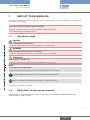
1.1
Symbols used
danger
Warns against an imminent danger.
▶▶Failure to observe this warning can result in death or in serious injury.
Warning
Warns against a potentially dangerous situation.
▶▶Failure to observe this warning can result in serious injury or even death.
attention
Warns against a possible risk.
▶▶Failure to observe this warning can result in substantial or minor injuries.
note
Warns against material damage.
▶▶Failure to observe this warning may result in damage to the device or system.
Indicates additional information, advice or important recommendations.
Refers to information contained in this manual or in other documents.
→→Indicates a procedure to be done.
1.2
Definition of the word "device"
The word "device" used within this manual refers to the dosing controller 8025 or 8035 Batch with serial
numbers higher or equal to 20 000.
5
English
Type 8025 - 8035 BATCH
Intended use and export of the device
2
Intended use and export of the
device
Use of the device that does not comply with the instructions could present risks to people, nearby
installations and the environment.
▶▶The dosing controller 8025 or 8035 Batch, installed in series with one or two valves, has been designed to
do the dosing of one or several quantities (volumes or masses) of a liquid.
▶▶This device must be protected against electromagnetic interference, ultraviolet rays and, when installed outdoors, the effects of climatic conditions.
▶▶This device must be used in compliance with the characteristics and commissioning and use conditions
specified in the contractual documents and in the user manual.
▶▶Requirements for the safe and proper operation of the device are proper transport, storage and installation, as
well as careful operation and maintenance.
▶▶Only use the device as intended.
▶▶Observe any existing restraints when the device is exported.
6
English
Type 8025 - 8035 BATCH
Basic safety information
3
Basic safety information
This safety information does not take into account:
• any contingencies or occurences that may arise during installation, use and maintenance of the devices.
• the local safety regulations for which the operating company is responsible including the staff in charge of
installation and maintenance.
Danger due to high pressure in the installation.
▶▶Stop the circulation of fluid, cut off the pressure and drain the pipe before loosening the process connections.
Danger due to electrical voltage.
▶▶Shut down the electrical power source of all the conductors and isolate it before carrying out work on the
system.
▶▶Observe all applicable accident protection and safety regulations for electrical equipment.
Danger due to high temperatures of the fluid.
▶▶Use safety gloves to handle the device.
▶▶Stop the circulation of fluid and drain the pipe before loosening the process connections.
Danger due to the nature of the fluid.
▶▶Respect the prevailing regulations on accident prevention and safety relating to the use of aggressive fluids.
Various dangerous situations
To avoid injury take care:
▶▶not to use the device in explosive atmospheres.
▶▶not to use the device for the dosing of gaz.
▶▶not to use the device in an environment incompatible with the materials it is made of.
▶▶not to subject the device to mechanical loads (e.g. by placing objects on top of it or by using it as a step).
▶▶not to make any external or internal modifications to the device.
▶▶to prevent any unintentional power supply switch-on.
▶▶to ensure that installation and maintenance work are carried out by qualified, authorised personnel in possession of the appropriate tools.
▶▶to guarantee a defined or controlled restarting of the process, after a power supply interruption.
▶▶to use the device only if in perfect working order and in compliance with the instructions provided in the operating instructions.
▶▶to observe the general technical rules when installing and using the device.
7
English
Type 8025 - 8035 BATCH
Basic safety information
note
Elements / Components sensitive to electrostatic discharges
▶▶This device contains electronic components sensitive to electrostatic discharges. They may be damaged if
they are touched by an electrostatically charged person or object. In the worst case scenario, these components are instantly destroyed or go out of order as soon as they are activated.
▶▶To minimise or even avoid all damage due to an electrostatic discharge, take all the precautions described in
the EN 61340-5-1 and 5-2 norms.
▶▶Also ensure that you do not touch any of the live electrical components.
note
The device may be damaged by the fluid in contact with.
▶▶Systematically check the chemical compatibility of the component materials of the device and the fluids likely
to come into contact with it (for example: alcohols, strong or concentrated acids, aldehydes, alkaline compounds, esters, aliphatic compounds, ketones, halogenated aromatics or hydrocarbons, oxidants and chlorinated agents).
8
English
Type 8025 - 8035 BATCH
General information
4
General information
4.1
Manufacturer's address and international contacts
To contact the manufacturer of the device, use following address:
Bürkert SAS
Rue du Giessen
BP 21
F-67220 TRIEMBACH-AU-VAL
You may also contact your local Bürkert sales office.
The addresses of our international sales offices are available on the internet at: www.burkert.com
4.2
Warranty conditions
The condition governing the legal warranty is the conforming use of the device in observance of the operating
conditions specified in these operating instructions.
4.3
Information on the Internet
You can find the user manuals and technical data sheets regarding the type 8025 or 8035 Batch at:
www.burkert.com
9
English
Type 8025 - 8035 BATCH
Description
5
Description
5.1
Area of application
When mounted in series with one or two valves the dosing controller 8025 or 8035 Batch enables the dosing of
one or several quantities of a liquid.
It controls the opening or closing of the valves via the relay outputs and counts the quantity of flown liquid.
The dosing is done either locally by pressing the navigation keys under the display or remotely by a PLC via one
up to four digital inputs.
The dosing principle is described in chap. “9.5”.
The eight available dosing modes are described in chap. “9.6”.
5.2
General description
The 8025 Batch is a dosing controller available in compact, wall-mounted or panel-mounted versions and the
8035 Batch is a dosing controller available in compact versions.
• A compact version of the 8025 Batch is made up of a flow sensor with paddle wheel and an electronic module
(electronics integrated in a housing with cover and lid, display and 2 cable glands).
• A compact version of the 8035 Batch is made up of a flow sensor-fitting type S030 with paddle wheel and an
electronic module SE35 (electronics integrated in a housing with cover and lid, display and 2 cable glands).
• A panel-mounted version is an electronics integrated in an open housing with display.
• A wall-mounted version is an electronics integrated in a housing with cover, display and 5 cable glands.
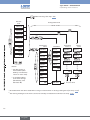
The device has four digital inputs (called DI1 to DI4), two transistor outputs (called DO1 and DO4, which can
be parametered), two relay outputs (called DO2 and DO3, which can be parametered) and four totalizers (two
volume or mass totalizers and two totalizers of the done dosings).
Depending on the version the device is energized by a 12-36 V DC or a 115/230 V AC power supply.
Electrical connection is made on the terminal blocks of the electronic board, either directly or via 2 or 5 cable
glands.
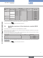
5.3
Available versions of type 8025 Batch
The following versions of the dosing controller 8025 Batch are available.
All these versions have four digital inputs (DI1 to DI4), two transistor outputs (DO1 and DO4), two relay outputs
(DO2 and DO3) and four totalizers.
10
English
Type 8025 - 8035 BATCH
Description
Version 8025
Batch
Supply voltage
Compact
12-36 V DC
Panel
Wall-mounted
Flow sensor
Type
Hall, short
Hall, short
Hall, long
115/230 V AC Hall, short
Hall, long
12-36 V DC
12-36 V DC
115/230 V AC -
UL 2)
Seal material
Order code
419520
564414
419522
419521
419529
419536
564415
433740
433741
no
yes
no
no
no
no
yes
no
no
FKM 1)
FKM 1)
FKM 1)
FKM 1)
FKM 1)
-
A set with a black EPDM seal for the flow sensor, an M20x1,5 cable gland plug, a 2x6mm multi-way seal and a
mounting instruction sheet, is delivered with each device in a compact version.
1)
2)
identified by the logo
5.4
on the name plate of the device.
Available versions of the electronic module SE35
Batch
The following versions of the electronic module SE35 Batch are available.
All these versions have four digital inputs (DI1 to DI4), two transistor outputs (DO1 and DO4), two relay outputs
(DO2 and DO3) and four totalizers.
A set with a black EPDM seal (not used), an M20x1,5 cable gland plug, a 2x6mm multi-way seal and a mounting
instruction sheet, is delivered with each electronic module.
Supply voltage
12-36 V DC
115/230 V AC
UL 2)
Order code
443360
564398
423926
no
yes
no
The order codes of the sensor-fitting S030 can be found within the related data sheet: refer to the data sheet at
www.burkert.com.
2)
identified by the logo
on the name plate of the device.
11
English
Type 8025 - 8035 BATCH
Description
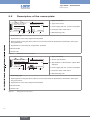
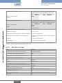
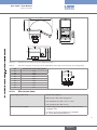
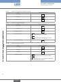
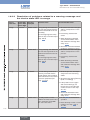
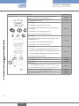
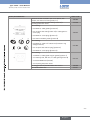
5.5
Description of the name plate
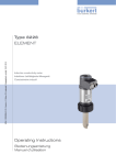
Made in France
1
1. Type of the device
3
2
BATCH 8025 HALL SHORT
DO1&4: 5-36V= 100mA
SUPPLY: 12-36V= 100 mA
DO2&3:Rel 230 /3A
IP65
2. Type of flow sensor
4
S/N 20 000
00419520
11
4. Protection class of the device
W4YMA
10 9
8
7
6
3. Power supply and max. current consumption
5. Manufacturing code
5
6. Conformity logo
7. Specifications of the relay outputs DO2 and DO3
8. Warning: Before using the device, take into account the technical specifications described in these operating instructions.
9. Specifications of the transistor outputs DO1 and DO4
10.Serial number
11.Order code
Figure 1:
Name plate of a non-UL device
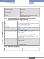
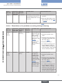
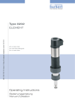
Made in France
1
3
2
1. Type of the device
4
BATCH SE35/8035 HALL
SUPPLY: 12-36V... 100 mA
DO1&4: 5-36V... 100mA
DO2&3:2xRelay 30V and 42V peak or 60V... max.
IP65
S/N 20 000
00564398
11
W4YMA
10 9
8
7
6
2. Sensor specifications
5
3. Specifications of the transistor outputs DO1
and DO4
4. Power supply and max. current consumption
5. Protection class of the device
6. Manufacturing code
7. Conformity logos
8. Warning: Before using the device, take into account the technical specifications described in these operating instructions.
9. Specifications of the relay outputs DO2 and DO3
10.Serial number
11.Order code
Figure 2:
Name plate of a UL device
12
English
Type 8025 - 8035 BATCH
Technical data
6
Technical data
6.1
Operating conditions
Ambient temperature
• 8025 compact,
115/230 V AC
• -10 to +50 °C
• 8035, 115/230 V AC
• -10 to +50 °C
• other versions
• -10 to +60 °C
Air humidity
< 80%, non condensated
Height above see level
max. 2000 m
Installation class
Class I acc. to UL 61010-1
Degree of pollution
Degree 2 acc. to EN 61010-1
Protection rating
acc to EN 60529
• compact version
• IP65, device wired and cable glands tightened and cover lid screwed tight.
• wall-mounted version
• IP65, device wired, cable glands tightened, cover lid screwed tight and
entry item nuts of the cable glands tightened at a screwing torque of
1.5 Nm.
• panel version
• front side IP65, rear side IP20
6.2
Conformity to standards and directives
The device conforms to the EC directives through the following standards:
• EMC: EN 61000-6-2, EN 61000-6-3
• LVD: EN 61010-1
• Environnemental testing: Vibration: EN 60068-2-6, Shock: EN 60068-2-27.
The UL devices with PU01 variable key comply with the following standards:
• UL 61010-1
• CAN/CSA-C22.2 n° 61010-1
6.3
Technical data
6.3.1
General technical data
Type of fitting
• 8025, compact version
• S020, DN20 (except DN20 v2) to DN400
• 8035
• S030, DN6 to DN65
13
English
Type 8025 - 8035 BATCH
Technical data
Fluid temperature, compact version
• 8025, compact version
The fluid temperature may be restricted by the fluid
pressure and the materials the fitting used is made
of. See “Figure 7”, chap. “7.2.1” or “Figure 14”, chap.
“7.5”.
• -15 to +80 °C
• 8035
Fluid pressure, compact version
• 8025, compact version
• -15 to +100 °C
The fluid pressure may be restricted by the fluid
temperature and the materials the fitting used is made
of. See “Figure 7”, chap. “7.2.1” or “Figure 14”, chap.
“7.5”.
• PN10
• 8035
• PN10 or PN16
Flow rate measurement, compact version
• Measurement range
• 0,3 to 10 m/s
• measurement error, with a K factor Teach-In procedure
• ±0,5 % of the full scale 1)
• Measurement error, with K factor of the fitting used
• ±(0,5 % of the full scale + 2.5 % of the measured
value) 1)
• Linearity
• ±0,5 % of the full scale 1)
• Repeatability
• ±0,4 % of the measured value
Determined in the following reference conditions: fluid = water, water and ambiant temperatures = 20 °C, upstream and
downstream distances respected, appropriate pipe dimensions.
1)
6.3.2
Mechanical data
Part
Material
Housing and cover with lid, compact version
PC, lid with UV filter
Housing and cover, wall-mounted version
ABS
Cable glands, compact or wall-mounted versions
PA
Open housing, panel-mounted version
PC
Foil
Polyester
4 screws
Stainless steel
Flow sensor holder, 8025 compact version
Axis and bearing of the paddle-wheel, 8025 compact
version
Paddle wheel, 8025 compact version
PVDF
O-ring seal, 8025 compact version
FKM (or EPDM, delivered with the device)
Nut, 8025 compact version
PC
Specifications of the fitting
refer to the related operating instructions
Cable clips
PA
14
English
ceramics
PVDF
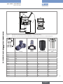
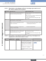
Type 8025 - 8035 BATCH
FLOW
88
(30)
164.50
203
85.5
(21)
91
R90
Technical data
ENTER
0....9
88
70
136
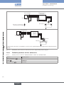
Dimensions of the dosing controller 8025 Batch, compact version [mm]
Table 1:
Dimension H of the dosing controller 8025 Batch, compact version, inserted in an S020 fitting [mm]
H
Figure 3:
T-fitting
Saddle
Spigot, in plastic
Welding tab with
radius, in stainless
steel
DN15
187
DN20
185
DN25
185
DN32
188
DN40
192
DN50
198
223
DN65
198
222
206
199
DN80
226
212
204
DN100
231
219
214
DN110
227
DN125
234
254
225
DN150
244
261
236
DN180
268
DN200
280
282
257
188
193
15
English
Type 8025 - 8035 BATCH
H
Technical data
DN250
Spigot, in plastic
300
Welding tab with
radius, in stainless
steel
317
DN300
312
336
DN350
325
348
DN400
340
T-fitting
Saddle
88
76
95
80
76
50
40
25
88
95
80
76
50
FLOW
ENTER
0....9
Drilling jig
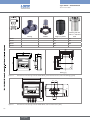
Figure 4:
Dimensions of the dosing controller 8025 Batch, panel-mounted version, and of the drilling jig [mm]
126
23
23
24
48
143
ENTER
0....9
90
120
FLOW
25.5
Figure 5:
Dimensions of the dosing controller 8025 Batch, wall-mounted version [mm]
16
English
Type 8025 - 8035 BATCH
Technical data
21
91
180
88
FLOW
ENTER
0....9
88
114
75
104
105
116
Dimensions of the electronic module SE35 Batch [mm]
Table 2:
Dimension H [mm] of the dosing controller 8035 Batch, depending on the DN of the sensor-fitting S030
DN
06
08
15
20
25
32
40
50
65
6.3.3
H [mm] with sensor-fitting S030
134
134
139
137
137
140
144
151
151
H
Figure 6:
Electrical data
Power supply 12-36 V DC
• filtered and regulated
• SELV circuit, with a safe energy level
• max. tolerance 12 V DC: -5 % or +10%
Power source (not supplied)
• max. tolerance 36 V DC: ±10 %
• limited energy source (in accordance to EN 61010-1,
paragraph 9.3)
• or Class 2 source (in accordance to standards
UL 1310/1585 and EN 60950-1)
17
English
Type 8025 - 8035 BATCH
Technical data
Power supply 115/230 V AC
• frequency
• 50/60 Hz
• supplied voltage
• 27 V DC, regulated
• current, 8025 wall-mounted version
• max. 250 mA
• current, 8025 and 8035 compact versions
• max. 125 mA
• integrated protection, compact version
• 125 mA time delay fuse
• integrated protection, wall-mounted version
• 250 mA time delay fuse
• power, 8025 wall-mounted version
• 6 VA
• power, 8025 and 8035 compact versions
Current consumption (without the consumption
of the loads, the inputs and the transistor
outputs)
• 3 VA
• 12-36 V DC fed version
• 90 mA (at 12 V DC) and 45 mA (at 36 V DC), with the
consumption of the relay outputs
• 115/230 V AC fed version
Transistor outputs DO1 and DO4
• 55 mA, with the consumption of the relay outputs
• type
• NPN/PNP (through wiring), polarized, potential-free
• DO1 function
• pulse output (can be configured and parametered)
• DO4 function
• dosing state (can be configured and parametered)
• frequency (f)
• 0,6-2200 Hz
• Electrical data
• 5-36 V DC, 100 mA max., voltage drop 2,7 V DC at
100 mA
• duty cycle if 0,6 < f < 300 Hz, all versions
• > 0.45
• duty cycle if 300 < f < 1500 Hz, 8025 wallmounted and panel-mounted versions
• > 0.4
• duty cycle if 1500 < f < 2200 Hz, 8025 wallmounted and panel-mounted versions
• < 0.4
• protection
• galvanically isolated, and protected against overvoltages,
polarity reversals and short-circuits
Relay outputs (DO2 and DO3)
18
• type
• normally open, can be inverted through parameter setting
• DO2 function
• valve 100%, cannot be modified
• DO3 function
• alarm (can be configured and parametered)
• electrical data of the load (non UL devices)
• 230 V AC / 3 A or 40 V DC / 3 A
• electrical data of the load (UL devices)
• max. 30 V AC and 42 V peak or max. 60 V DC, 3 A
• max. breaking capacity
• 750 VA (resistive load)
English
Type 8025 - 8035 BATCH
Technical data
Digital inputs DI1 to DI4
• commutation threshold Von
• 5 to 36 V DC
• commutation threshold Voff max.
• 2 V DC
• min. pulse duration
• 100 ms
• input impedance
• 9,4 kW
• protection
• galvanically isolated, and protected against polarity
reversals and voltage spikes
6.3.4
Specifications of the connected flow sensor (panelmounted and wall-mounted versions)
Signal originating from the remote
sensor
• type
• pulse, sine-wave (typical sensitivity 50 mV peak-to-peak at 250 Hz),
"on/off", or standard voltage 0-5 V DC
• frequency
• 0,6 Hz to 2,2 kHz, can be adjusted
• 36 V DC
depends on the position of selector "LOAD" on the electronic board of
the 8025.
See chap. “7.6.4” and “7.6.7”.
Power supply, if the dosing controller is supplied by the dosing controller depending on the position of
energized with a 12-36 V DC voltage
selector "SENSOR SUPPLY" of the 8025, either:
• max. voltage
Input impedance
• 5 V DC, 30 mA max.
• (L+)-12V: supply voltage (L+) of the dosing controller minus
12 V DC (minus 12,5 V DC max.), 80 mA max.
• L+: supply voltage (L+) of the dosing controller (minus 1,5 V DC
max.), 140 mA max.
Power supply, if the dosing controller is supplied by the dosing controller depending on the position of
energized with a 115/230 V AC voltage selector "SENSOR SUPPLY" of the 8025, either:
• 5 V DC, 30 mA max.
• (L+)-12V: 27 V DC minus 12 V DC (minus 12,5 V DC max.), 80 mA
max.
• L+: 27 V DC, 80 mA max.
6.3.5
Electrical connection
Type of connection
on the terminal blocks of the electronics (and through
cable glands for the compact and wall-mounted
versions)
19
English
Type 8025 - 8035 BATCH
Technical data
Cable specifications
• cable type
• shielded
• Cross section of wires
• 0.2 to 1.5 mm2
• Diameter of each cable (for the M20x1,5 cable
glands of the compact version)
• if only one cable is used per M20x1,5 cable gland: 6
to 12 mm
• Diameter of each cable (for the cable glands
M16x1,5 of the wall-mounted version)
20
English
• if two cables are used per M20x1,5 cable gland:
4 mm, with the supplied multi-way seal
• 4 to 8 mm
Type 8025 - 8035 BATCH
Installation and wiring
7
Installation and wiring
7.1
Safety instructions
danger
Danger due to high pressure in the installation.
▶▶Stop the circulation of fluid, cut off the pressure and drain the pipe before loosening the process connections.
▶▶Observe the fluid temperature/pressure dependency depending on the fitting used.
Danger due to electrical voltage.
▶▶Shut down the electrical power source of all the conductors and isolate it before carrying out work on the
system.
▶▶Observe all applicable accident protection and safety regulations for electrical equipment.
Danger due to high temperatures of the fluid.
▶▶Use safety gloves to handle the device.
▶▶Stop the circulation of fluid and drain the pipe before loosening the process connections.
Danger due to the nature of the fluid.
▶▶Respect the prevailing regulations on accident prevention and safety relating to the use of aggressive fluids.
Warning
Risk of injury due to non-conforming installation.
▶▶The electrical installation can only be carried out by qualified and skilled staff with the appropriate tools.
▶▶Install appropriate safety systems (correctly rated fuse and/or circuit-breaker); For the 115/230 V AC fed versions, insert a safety system between the phase and the neutral conductor.
▶▶Respect standard NF C 15-100 / IEC 60364.
Risk of injury due to unintentional switch on of power supply or uncontrolled restarting of the
installation.
▶▶Take appropriate measures to avoid unintentional activation of the installation.
▶▶Guarantee a set or controlled restarting of the process subsequent to any intervention on the device.
Protect this device against electromagnetic interference, ultraviolet rays and, when installed outdoors, the effects of the climatic conditions.
21
English
Type 8025 - 8035 BATCH
Installation and wiring
7.2
Installation of a 8025 Batch, compact version
The dosing controller 8025 Batch has to be inserted into an S020 fitting mounted on a pipe.
7.2.1
Recommandations for installing the 8025 Batch, compact
version, on the pipe
→→Choose an S020 fitting appropriate to the velocity of the fluid inside the pipe: refer to the graphs below.
Example:
Flow rate
US gpm
20000
10000
5000
2000
1000
500
200
100
50
20
10
5
2
1
0.5
0.2
0.1
0.05
l/min
100000
m3/h
5000
DN 400
DN 350
50000
DN 300
30000 2000
20000
10000
DN 250
1000
DN 200
DN 150
500
DN 125
5000
3000
2000
1000
DN 80
DN 65
100
DN 50 (DN65)*
50
DN 40 (DN50)*
DN 32 (DN40)*
20
100
DN 25 (DN32)*
DN 20 (DN25)*
10
DN 15 (DN15 / DN20)*
5
50
10
1
Example
0.5
5
0.2
2
1
0.05
0.02
0.01
0.1
0.3
• with welding end connections acc. to
SMS 3008, BS 4825 / ASME BPE or
DIN 11850 Rg 2,
• with Clamp connections acc.
to SMS 3017 / ISO 2852,
BS 4825 / ASME BPE or DIN 32676.
0.1
0.5
0.2
* For the fittings:
• with external thread connections acc. to
SMS 1145,
2
20
-- nominal flow rate: 10 m3/h,
-- optimum flow velocity: between 2 and
3 m/s.
• Recommended diameter: DN40 (or DN50
for the asterisked fittings).
DN 100
200
500
200
• Specification:
0.3
0.5
1
0.5
1
3
3
5
10
5
10 m/s
30
fps
Fluid velocity
22
English
Type 8025 - 8035 BATCH
Installation and wiring
→→Observe the fluid temperature/pressure dependency depending on the material of fitting S020 used:
Operating range
P (bar)
11
10
9
Metal
PVDF
8
PVDF (PN10)
PVC + PP
7
6
5
4
PVC (PN10)
3
2
PP (PN10)
1
0
Figure 7:
-15
0
+20
+40
+60
+80 T (°C)
Fluid pressure /temperature dependency curves for a 8025 Batch, compact version, inserted into a fitting
S020 in metal, PVDF, PP or PVC
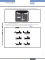
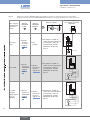
→→Install the device on the pipe in such a way that the upstream and downstream distances are respected
according to the design of the pipes, refer to standard EN ISO 5167-1 and Figure 8 :
flow direction
50 x DN 5 x DN
With control valve
25 x DN 5 x DN
Pipe with 2 elbows at 90°
18 x DN 5 x DN
With pipe expansion
Figure 8:
40 x DN 5 x DN
Pipe with 2 elbows at 90° in 3
dimensions
20 x DN 5 x DN
Pipe with 1 elbow at 90° or 1
T-piece
15 x DN 5 x DN
With pipe reduction
Upstream and downstream distances depending on the design of the pipes.
23
English
Type 8025 - 8035 BATCH
Installation and wiring
→→Respect the following additional mounting conditions to ensure that the measuring device operates correctly:
-- Ensure that the pipe is always filled in the section around the device (see Figure 9).
-- When mounting vertically ensure that the flow direction is in an upward direction (see Figure 9).
Horizontal mounting
Correct
Incorrect
Vertical mounting
flow direction
Correct
Figure 9:
Incorrect
Filling of the pipe
→→If necessary, use a flow conditioner to improve measurement precision.
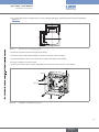
7.2.2
Installation onto the pipe
→→Install the S020 fitting into the pipe taking into account the recommendations in
chap. “7.2.1”.
→→Check that there is a seal on the fitting and that it is not damaged. Replace the seal
1
if necessary.
→→Check that there is a seal (mark 6) on the flow sensor.
6
→→Insert the nut (mark 3) on the fitting.
2
4
3
→→Insert the snap ring (mark 2) into the groove (mark 5).
5
→→Position the device in order the arrow on the side of the housing indicates the direction
of the flow. The totalizers will increment.
→→Insert the device (mark 1) into the fitting.
→→Tighten the nut (mark 3) by hand on the device.
Figure 10:
Installation of a 8025 Batch, compact version, into an S020 fitting
7.3
Installation of a panel version
Install the panel version of the device in a cabinet with a protection class at least IP54 to ensure a
degree of pollution 2 inside the cabinet.
24
English
Type 8025 - 8035 BATCH
Installation and wiring
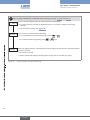
→→To cut the opening in the cabinet door, use the supplied drilling jig, respecting the dimensions indicated in
“Figure 11”.
95
80
76
50
95
80
76
50
Figure 11:
Dimensions of the drilling jig [mm]
→→Insert the 4 screws in the housing (from the front).
→→Insert the seal on the external threads of the 4 screws (rear of the housing).
→→Put the assembly on the cutout, electronics turned to the inside of the cabinet.
→→Put the 4 washers on the 4 screws.
→→Put a nut on each of the 4 screws and tighten the nuts to secure the device to the cabinet.
Screws
Washer
Nut
Cable clip
Seal
Figure 12:
Installation of a 8025, panel version
25
English
Type 8025 - 8035 BATCH
Installation and wiring
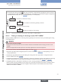
7.4
Installation of a wall-mounted version
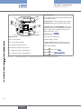
NOTE
Risk of material damage if the cable glands are not tightly screwed on the housing
▶▶Before installing the wall-mounted housing on its support, tighten the nuts of the entry item of the cables
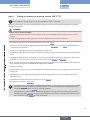
glands at a torque of 1.5 Nm.
The device in a wall-mounted version has 4 holes in the bottom of the housing.
→→Remove the blanking strips covering the screws.
FLOW
Blanking strips
ENTER
0....9
Nut of the entry item
→→Loosen the 4 screws and open the cover to get access to the holes [].
106 mm
Iout
L+
(AO1)
(L+)-12V
470
P+
PE PE PE
NPN/PNP
SENSOR TYPE
COIL
NPN/PNP
DO2
SENSOR
L N
ON
FLOW
OFF
NC COIL
3
PE
39K
SUPPLY
L+
COIL/PNP
PULSE
INPUT
P-
PULSE
DO1
LOAD
+5V
SUPPLY
- +
2
PE
SENSOR
2.2K
1
L-
Supply
NC 12..36Vdc
DO3
5 6
7 8 9 10
1
Figure 13:
106 mm
Univ
Batch
PE
ISOG
DO4
DI4
DI3
DI2
DI1
230V
SOURCE
SINK
CURRENT
BINARY
1
T 250 mA
1
1
Installation of a wall-mounted version
→→Secure the housing to the support respecting the dimensions indicated in “Figure 13”.
→→Wire acc. to instructions in chap. “7.6”.
→→Close the housing and tighten the 4 screws of the cover.
7.5
Installation of a 8035 Batch
The electronic module SE35 Batch can be installed on a pipe by using a sensor-fitting S030.
→→Observe the fluid temperature/pressure dependency depending on the material of the sensor-fitting S030 used:
26
English
Type 8025 - 8035 BATCH
Installation and wiring
Operating range
P (bar)
16
15
Metal
14
13
12
11
10
9
PVDF
8
PVDF (PN10)
PVC + PP
7
6
5
4
PVC (PN10)
3
2
PP (PN10)
1
0
Figure 14:
-15
0
+20
+40
+60
+80
+100 T (°C)
Fluid pressure /temperature dependency curves for an SE35 Batch mounted on a sensor-fitting S030 in metal,
PVDF, PP or PVC
→→Choose an S030 fitting appropriate to the velocity of the fluid inside the pipe: refer to the graphs below.
Example:
gpm
m3/h
1000 l/min 200
3000
500 2000
100
200
100
50
Flow rate
20
10
5
2
1
0.5
0.2
0.1
0.05
1000
• Specification:
DN65
DN50 (DN65)*
DN40 (DN50)*
DN32 (DN40)*
DN25 (DN32)*
50
500
20
200
100
DN20 (DN25)*
10
5
DN15 (DN15 or
DN20)*
2
DN08
1
DN06
-- nominal flow rate: 10 m3/h,
-- optimum flow velocity: between 2 and 3 m/s.
• Recommended diameter: DN40 (or DN50 for the
asterisked fittings).
50
20
10
0.5
* For the fittings:
0.2
• with external thread connections acc. to
SMS 1145,
5
2
1
0.1
• with welding end connections acc. to SMS 3008,
BS 4825 / ASME BPE or DIN 11850 Rg 2,
0.05
0.5
0.02
0.2
0.01
0.1
0.3 0.5
0.3 0.5
1
1
3
5
3
10
5
10 m/s
30 fps
Fluid velocity
• with Clamp connections acc. to
SMS 3017 / ISO 2852, BS 4825 / ASME BPE or
DIN 32676.
27
English
Type 8025 - 8035 BATCH
Installation and wiring
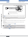
→→Respect the installation instructions given in the operating instructions
of the fitting.
2
→→Insert the electronic module SE35 [] in the sensor-fitting S030 [1].
→→Secure the electronic module to the sensor-fitting by a 30° turn.
→→Secure the unit by tightening screw [].
3
1
Figure 15:
Installation of a 8035 Batch
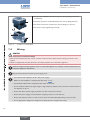
7.6
Wiring
danger
Risk of injury due to electrical voltage.
▶▶Shut down the electrical power source of all the conductors and isolate it before carrying out work on the
system.
▶▶Observe all applicable accident protection and safety regulations for electrical equipment.
Insert the supplied stopper gaskets into the unused cable glands of a compact or wall-mounted version to
ensure the tightness of the device.
Only move the selectors when the power supply is off.
• Use a filtered and regulated 12-36 V DC power supply.
• Make sure the installation is equipotential. See chap. “7.6.1”.
• Use shielded cables with a temperature limit of 80 °C minimum.
• Do not install the cables near high voltage or high frequency cables; If this cannot be avoided, observe a
min. distance of 30 cm.
• Protect the device power supply by means of a 300 mA fuse and a switch.
• Protect the power supply of each transistor output by means of a 125 mA fuse.
• Protect the relays by means of a max. 3 A fuse and a circuit breaker (depending on the process).
• Do not apply both a dangerous voltage and a safety extra-low voltage to the relays.
28
English
Type 8025 - 8035 BATCH
Installation and wiring
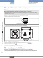
7.6.1
Equipotentiality of the installation
To ensure the equipotentiality of the installation (power supply - device - fluid):
→→Connect together the various earth spots in the installation to eliminate the potential differences that may
occur between different earthes.
→→Observe faultless earthing of the shield of the power supply cable, at both ends.
→→Connect the negative power supply terminal to the earth to suppress the effects of common mode currents. If
this connection cannot be made directly, a 100 nF/50 V capacitor can be fitted between the negative power
supply terminal and the earth.
→→Special attention has to be paid if the device is installed on plastic pipes because there is no direct earthing
possible. Proper earthing is performed by earthing together the metallic instruments such as pumps or valves,
that are as close as possible to the device. If no such instrument is near the device, insert metallic earth rings
inside the plastic pipes upstream and downstream the device and connect these parts to the same earth. The
earth rings must be in contact with the fluid.
Power cable shield
12-36VDC
+
Power supply
(*)
Metallic pipes
Power cable shield
12-36VDC
+
-
Equipment such as
valves, pumps,...
(*)
Power supply
Plastic pipes
(*) If a direct earth connection is not possible, fit a 100 nF/50 V capacitor between the negative power supply terminal and
the earth.
Figure 16:
8025 compact version and 8035, equipotentiality skeleton diagrams
29
English
Type 8025 - 8035 BATCH
Installation and wiring
8025 Batch, panel- or
wall-mounted
Power cable shield
+
Power supply
(*)
Flow sensor
Pipes in plastic
Valve, pump,... (or earth rings, not
provided, inserted into the pipe)
Power cable shield
+
Power supply
8025 Batch,
panel- or
wall-mounted
(*)
Flow sensor
Metal pipe
If a direct earth connection is not possible, fit a 100 nF / 50 V capacitor between the negative power supply terminal and
the earth.
1
Figure 17:
8025 Batch, panel-mounted or wall-mounted version, equipotentiality skeleton diagram
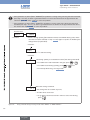
7.6.2
Default position of the selectors
Table 3:
Default positions of selectors "SENSOR SUPPLY", "LOAD" and "SENSOR TYPE"
Selector
Default position
SENSOR SUPPLY ( A )
L+
LOAD ( B )
2.2KOhms
SENSOR TYPE ( C )
NPN/PNP
30
English
Type 8025 - 8035 BATCH
Installation and wiring
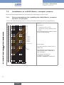
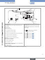
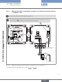
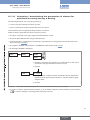
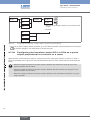
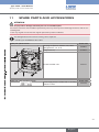
7.6.3
Terminal assignment and use of the selectors
1
6
2
SOURCE
SINK
CURRENT
Univ
Batch
B
1
PE
P-
P+
PULSE
DO1
+5V
L+
(L+)-12V
470
39K
NPN/PNP
2.2K
C
SENSOR TYPE
COIL
NC COIL
3
PE
DO2
NPN/PNP
SENSOR
Terminal block 1
• NC: not connected
• L+: V+ (positive voltage)
• L-: 0V (power supply ground)
• PE: protective earth, factory wired
• P-: negative transistor output (DO1)
ON
FLOW
PE: shieldings of the power supply cable and the
input / output cables
Terminal block 3: wiring the DO2 relay output.
PE PE PE
SENSOR
SUPPLY
- +
2
L-
Supply
OFF
5
L+
NC 12..36Vdc
COIL/PNP
PULSE
INPUT
PE
ISOG
DO4
DI4
DI3
DI2
DI1
Iout
(AO1)
SUPPLY
BINARY
LOAD
A
Terminal block 2
Terminal block 4: wiring the DO3 relay output.
Connector 5: connection of the flow sensor
Terminal block 6 "BINARY"
3
• DI1 to DI4: 4 digital inputs
4
• DO4: transistor output
DO3
• ISOG: ISOGND, ground common to the 4
digital inputs and the transistor output DO4.
• PE: cable shielding
Selector A : see chap. “7.6.4”.
Selector B : see chap. “7.6.4”.
Selector C : see chap. “7.6.4”.
• P+: positive transistor output (DO1)
Figure 18:
Terminal assignment of a 12-36 V DC fed compact version
31
English
Type 8025 - 8035 BATCH
Installation and wiring
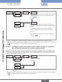
1
6
2
SOURCE
SINK
CURRENT
Univ
Batch
B
PE
P-
+5V
L+
(L+)-12V
470
NPN/PNP
2.2K
39K
PE PE PE
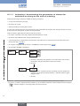
Terminal block 4: wiring the DO3 relay output.
C
3
Terminal block 5 "FLOW SENSOR": Wiring the
remote flow sensor. The wiring depends on the
type of output signal originating from the flow
sensor: See chap. “7.6.7”.
4
Terminal block 6 "BINARY"
SENSOR TYPE
COIL
NC COIL
3
PE
DO2
NPN/PNP
ON
FLOW
DO3
SENSOR
5
PE: shieldings of the power supply cable and the
input / output cables
Terminal block 3: wiring the DO2 relay output.
P+
PULSE
DO1
SENSOR
SUPPLY
- +
2
L-
Supply
OFF
1
L+
NC 12..36Vdc
COIL/PNP
PULSE
INPUT
PE
ISOG
DO4
DI4
DI3
DI2
DI1
Iout
(AO1)
SUPPLY
BINARY
LOAD
A
Terminal block 2
Terminal block 1
• DI1 to DI4: 4 digital inputs
• NC: not connected
• DO4: transistor output
• L+: V+ (positive voltage)
• ISOG: ISOGND, ground common to the 4
digital inputs and the transistor output DO4.
• L-: 0V (power supply ground)
• PE: protective earth, factory wired
• P-: negative transistor output (DO1)
• P+: positive transistor output (DO1)
Figure 19:
• PE: cable shielding
Selector A : see chap. “7.6.7”.
Selector B : see “Table 5”, page 40
Selector C : see chap. “7.6.7”.
Terminal assignment of a 12-36 V DC fed panel-mounted or wall-mounted version
32
English
Type 8025 - 8035 BATCH
Installation and wiring
2
8
1
T 125 mA
SOURCE
SINK
CURRENT
B
PE
ISOG
DO4
DI4
DI3
DI2
DI1
P-
P+
PULSE
DO1
PE PE PE
SENSOR
+5V
(L+)-12V
470
2.2K
NPN/PNP
PULSE
INPUT
PE
NC COIL
3
PE
39K
SENSOR TYPE
COIL
NPN/PNP
DO2
FLOW
SENSOR
ON
L N
L-
Supply
L+
SUPPLY
- +
2
L+
NC 12..36Vdc
OFF
230V
D
1
Iout
(AO1)
COIL/PNP
3
4
Univ
Batch
SUPPLY
BINARY
LOAD
A
DO3
C
5
7
6
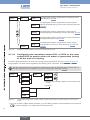
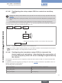
Terminal block 1
Terminal block 5: wiring the DO2 relay output.
PE: shieldings of the power supply cable and the input /
output cables
Terminal block 6: wiring the DO3 relay output.
Terminal block 2
Terminal block 7: wiring of the 115/230 V AC
power supply
• NC: not connected
• L+: V+ (red wire, factory wired)
• L-: 0V (black wire, factory wired)
Mark 8 : time-delay fuse to protect the
115/230 V AC power supply
• PE: protective earth (green/yellow wire, factory wired)
Selector A : see chap. “7.6.4”;
• P-: negative transistor output (DO1)
Selector B : see chap. “7.6.4”;
• P+: positive transistor output (DO1)
Selector C : see chap. “7.6.4”.
Connector 3: connection of the flow sensor
Selector D : see chap. “7.6.4”.
Terminal block 4 "BINARY"
• DI1 to DI4: 4 digital inputs
• DO4: transistor output
• ISOG: ISOGND, ground common to the 4 digital inputs
and the transistor output DO4.
• PE: cable shielding
Figure 20:
Terminal assignment of a 115/230 V AC fed compact version
33
English
Type 8025 - 8035 BATCH
Installation and wiring
1
PE
P-
P+
PULSE
DO1
PE PE PE
SENSOR
+5V
L+
(L+)-12V
470
39K
NPN/PNP
2.2K
SUPPLY
- +
2
L-
Supply
SENSOR TYPE
COIL
NPN/PNP
NC COIL
3
PE
L N
DO2
ON
FLOW
OFF
1
L+
NC 12..36Vdc
COIL/PNP
PULSE
INPUT
PE
ISOG
DO4
DI4
DI3
DI2
DI1
Iout
(AO1)
SUPPLY
B
3
Univ
Batch
LOAD
BINARY
T 250 mA
SOURCE
SINK
CURRENT
A
D
9
230V
2
5 6
DO3
SENSOR
7 8 9 10
4
C
5
6
8
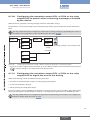
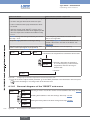
Terminal block 1
Terminal block 5: wiring the DO2 relay output.
PE: factory wired shield.
Terminal block 6: wiring the DO3 relay output.
Terminal block 2
Terminal block 7
• NC: not connected
• terminal 5 not connected
• L+: V+ (red wire, factory wired)
• terminal 6: positive 27 V DC power supply,
available to energize an external instrument
• L-: 0V (black wire, factory wired)
• PE: protective earth, factory wired
• terminal 7: 0V (earth of the power supply
available to energize an external instrument)
• P-: negative transistor output (DO1) (brown wire, factory
wired)
• terminal 8: protective earth for the cable
shieldings
• P+: positive transistor output (DO1) (white wire, factory
wired)
• terminal 9: negative transistor output (DO1)
Terminal block 3 "BINARY"
• DI1 to DI4: 4 digital inputs
• DO4: transistor output
• ISOG: ISOGND, ground common to the 4 digital inputs
and the transistor output DO4.
34
7
• terminal 10: positive transistor output (DO1)
Terminal block 8: wiring of the 115/230 V AC
power supply
Mark 9 : time-delay fuse to protect the
115/230 V AC power supply
Selector A : see chap. “7.6.7”.
• PE: cable shielding
Selector B : see “Table 5”, page 40.
Terminal block 4 "FLOW SENSOR": Wiring the remote
flow sensor. The wiring depends on the type of output
signal originating from the flow sensor: see chap. “7.6.7”.
Selector C : see chap. “7.6.7”.
Figure 21:
Selector D : see chap. “7.6.7”.
Terminal assignment of a wall-mounted version, 115/230 V AC
English
Type 8025 - 8035 BATCH
Installation and wiring
7.6.4
Wiring a compact version
Only move the selectors when the power supply is off.
Insert the supplied stopper gasket into the unused cable gland to ensure the tightness of the device.
• Unscrew the unused cable gland.
• Remove the transparent disk.
• Insert the supplied stopper gasket.
• Screw the nut of the cable gland.
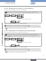
→→Set the selector "SENSOR TYPE" on "NPN/PNP". See “Figure 22”.
Never set selector "SENSOR TYPE" on the left on a compact version.
Selector C makes it possible to configure the type of signal received from the flow sensor.
SENSOR TYPE
COIL
C
NPN/PNP
SENSOR TYPE
COIL
NPN/PNP
→→On a compact version, set the selector on the right (default position).
Figure 22:
Using selector "SENSOR TYPE" on a compact version
→→Set selector "SENSOR SUPPLY" depending on the value of the power supply of the dosing controller. See
“Table 4”.
→→Set selector "LOAD": See “Table 4”.
35
English
Type 8025 - 8035 BATCH
Installation and wiring
Position of selectors "SENSOR TYPE", "SENSOR SUPPLY" and "LOAD" on a compact version
Selector "SENSOR SUPPLY"
Selector "LOAD"
L+
(L+)-12V
SUPPLY
A
+5V
B
470
2.2K
COIL/PNP
SENSOR
Selector
"SENSOR TYPE"
( C)
39K
LOAD
Table 4:
The flow sensor of the compact version needs a minimum
voltage supply of 5 V DC :
→→If the device is fed with a voltage ≥ 12 V DC and
→→Set the
selector on
"NPN/PNP"
(“Figure 22”)
< 17 V DC, set the voltage selector "SENSOR
SUPPLY" on "5V" or "L+".
→→If the device is fed with a voltage ≥ 17 V DC, the
→→Set selector "LOAD":
• either on "2.2k": the load
resistance R is then 2,2 kW
voltage selector "SENSOR SUPPLY" can be set to any • either on "470": the load
resistance R is then 470 W
position.
→→If the device is fed with a 115/230V AC voltage, set
the voltage selector "SENSOR SUPPLY" on "L+".
→→If the compact version of the 8025 Batch is energized with a 115/230 V AC power supply, set selector D as
shown in “Figure 23”.
Selector D makes it possible to configure the supply voltage of the device in a 115/230 V AC version.
D
→→Energize the device with a
230 V AC voltage.
Figure 23:
→→Energize the device with a
230V
115V
115 V AC voltage.
Selector of the supply voltage on a 115/230 V AC version
→→Before wiring the device insert the supplied cable clips into the slots of
the electronic board.
Figure 24:
Inserting the cable clips
→→Install the device as described in chap. “7.2” or “7.5”.
→→Wire acc. to chap. “7.6.9”, “7.6.12” and “9.6”.
→→Secure the power supply cable and the relay connection cables, with the cable clips.
→→Close the housing and tighten the 4 screws of the cover.
36
English
Type 8025 - 8035 BATCH
Installation and wiring
7.6.5
Wiring a panel version
Only move the selectors when the power supply is off.
→→Install the device as described in chap. “7.3”.
→→Set the selectors "SENSOR TYPE", "SENSOR SUPPLY" and "LOAD": see chap. “7.6.7”.
→→Before wiring the device insert the supplied cable clips into the slots of
the electronic board.
Figure 25:
Inserting the cable clips
→→Wire acc. to chap. “7.6.7”, “7.6.9”, “7.6.12” and “9.6”.
→→Secure the power supply cable, the flow sensor connection cable and the relay connection cables, with the
cable clips.
7.6.6
Wiring a wall-mounted version
Only move the selectors when the power supply is off.
Insert the supplied stopper gaskets into the unused cable glands to ensure the tightness of the device.
• Unscrew the unused cable gland.
• Remove the transparent disk.
• Insert the supplied stopper gasket.
• Screw the nut of the cable gland.
→→Install the device as described in chap. “7.4”.
→→Set the selectors "SENSOR TYPE", "SENSOR SUPPLY" and "LOAD": see chap. “7.6.7”.
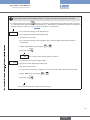
→→If the wall-mounted version is energized with a 115/230 V AC power supply, set selector D
as shown in
“Figure 26”.
Selector D makes it possible to configure the supply voltage of the device in a 115/230 V AC version.
D
→→Energize the device with a
230 V AC voltage.
Figure 26:
→→Energize the device with a
230V
115V
115 V AC voltage.
Selector of the supply voltage on a 115/230 V AC version
→→Loosen the nuts of the cable glands.
37
English
Type 8025 - 8035 BATCH
Installation and wiring
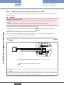
→→Insert each cable through a nut than through the cable gland, using the cable glands as shown in “Figure 27”.
Cables of the relay outputs DO2 and
DO3
Cable of the flow sensor
Power supply cable
12-36 V DC or 115/230 V AC
Cable of the digital inputs and
the DO1 and DO4 outputs
Figure 27:
Using the cable glands on a wall-mounted version
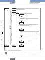
→→On a 115/230 V AC fed wall-mounted version, remove both terminal blocks (marked 7 and 8 in “Figure 21”)
from the housing.
→→Before wiring the device insert the supplied cable clips into the slots of
the electronic board and of the 115/230 V AC power supply board if
the device has such a board.
Figure 28:
Inserting the cable clips
→→Depending on the operating voltage of the device, wire according to chap. “7.6.7”, “7.6.9” to “7.6.12” and
“9.6”.
→→Insert the two terminal blocks (marked 7 and 8 in “Figure 21”) into their original position.
→→Letting the housing stay completely open, secure the power supply cable, the flow sensor connection cable
and the relay connection cables, with the cable clips.
→→Tighten the cable glands making sure the cable in the housing is long enough to allow complete opening of
the housing.
→→Close the cover.
→→Tighten the 4 screws.
→→Put the blanking strips on the housing.
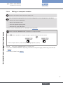
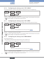
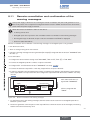
7.6.7
Connecting the remote flow sensor to a panel-mounted or
wall-mounted version
Only move the selectors when the power supply is off.
Insert the supplied stopper gaskets into the unused cable glands to ensure the tightness of the device.
• Unscrew the unused cable gland.
• Remove the transparent disk.
• Insert the supplied stopper gasket.
• Screw the nut of the cable gland.
38
English
Type 8025 - 8035 BATCH
Installation and wiring
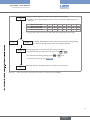
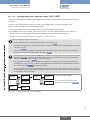
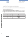
Before connecting the flow sensor to the dosing controller 8025 Batch, in a panel-mounted or a wallmounted version:
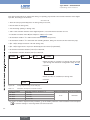
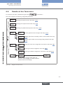
• Set selector "SENSOR TYPE" depending on the output signal originating from the flow sensor. See
“Figure 29” and “Table 5”, page 40.
• If selector "SENSOR TYPE" is set on "NPN/PNP", set selector "SENSOR SUPPLY" depending on the
dosing controller supply voltage. See “Figure 30” and “Table 5”, page 40.
• Set selector "LOAD" depending on the type of signal sent out by the flow sensor and on the load
wanted on terminal 1 "PULSE INPUT" of terminal block "FLOW SENSOR". See “Table 5”, page 40.
Selector C makes it possible to configure the type of signal the 8025 Batch, panel- or wall-mounted version,
receives from the remote flow sensor.
SENSOR TYPE
COIL
NPN/PNP
→→Set the selector on the right (default position) when
the signal from the flow sensor which is connected to
the 8025 Batch is either:
• a pulse signal, NPN or PNP
C
SENSOR TYPE
COIL
NPN/PNP
→→Set the selector on the left when the
signal from the flow sensor which is
connected to the 8025 Batch is a sinewave signal (coil).
• an "on/off" signal (Reed relay for example)
• a 0-5 V DC standard voltage signal (TTL, for example)
Figure 29:
Using selector "SENSOR TYPE" on a panel- or wall-mounted version
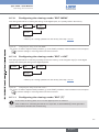
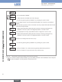
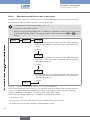
When selector "SENSOR TYPE" above
is set on "NPN/PNP", selector A
makes it possible to configure the supply
voltage for the remote flow sensor.
A
+5V
L+
(L+)-12V
Figure 30:
SUPPLY
SENSOR
→→If the device is energized with a 115/230 V AC power supply, set
selector "SENSOR SUPPLY" on "L+" (default position).
→→If the device is energized with a 12-36 V DC power supply, set
the voltage selector "SENSOR SUPPLY" depending on the
voltage supply needed by the remote flow sensor: "+5V", "L+" or
"(L+)-12V" (default position).
Using selector "SENSOR SUPPLY" on a panel- or wall-mounted version
39
English
Type 8025 - 8035 BATCH
Installation and wiring
Position of selectors "SENSOR TYPE" and "LOAD" of a panel- or wall-mounted version, and terminal
assignment of terminal block "FLOW SENSOR" depending on the signal emitted by the remote flow sensor
B
470
2.2K
39K
SUPPLY
- +
1
2
NPN/PNP
Selector
"SENSOR
SUPPLY"
(A)
Terminal assignment of
terminal block "FLOW
SENSOR"
PULSE
INPUT
Selector
"SENSOR
TYPE"
( C)
COIL/PNP
Type of signal
emitted by the
remote flow
sensor
Selector "LOAD"
LOAD
Table 5:
NC COIL
3
PE
FLOW
SENSOR
8025
→→Set selector "LOAD" on
→→Set the
sine-wave
(coil)
selector
on "COIL"
(“Figure
29”)
→→Any
position.
"39K": the input impedance
on terminals 1 and 2 of
terminal block "FLOW
SENSOR" will then be
39 kW
39 kΩ
NC
1 2 3 PE
Flow sensor
8025
39 kΩ
→→Set the
pulse, PNP
selector on
"NPN/PNP"
(“Figure
29”)
→→Set the
selector as
shown in
“Figure 30”.
1 2 3 PE
→→Set selector "LOAD" on
"39K": the input impedance
on terminals 1 and 2 of
terminal block "FLOW
SENSOR" will then be
39 kW
Flow sensor
8025
39 kΩ
1 2 3 PE
0-5 V DC
standard
voltage signal
(TTL, for
example)
→→Set the
selector on
"NPN/PNP"
(“Figure
29”)
→→Set the
selector as
shown in
“Figure 30”.
→→Set selector "LOAD" on
"39K": the input impedance
on terminals 1 and 2 of
terminal block "FLOW
SENSOR" will then be
39 kW
Flow sensor
40
English
Type 8025 - 8035 BATCH
Installation and wiring
2.2K
39K
1
SUPPLY
- +
2
NPN/PNP
B
470
PULSE
INPUT
Selector
"SENSOR
SUPPLY"
(A)
Terminal assignment of
terminal block "FLOW
SENSOR"
LOAD
Selector
"SENSOR
TYPE"
( C)
COIL/PNP
Type of signal
emitted by the
remote flow
sensor
Selector "LOAD"
NC COIL
3
PE
FLOW
SENSOR
8025
+3 V
R
→→Set the
selector on
"NPN/PNP"
(“Figure
29”)
pulse, NPN
→→Set the
1 2 3 PE
→→Set selector "LOAD":
• either on "2.2k": the load
selector as
resistance R is then 2,2 kW
shown in
“Figure 30”. • either on "470": the load
resistance R is then 470 W
Flow sensor
8025
+3 V
R
"on/off" signal
(Reed relay for
example)
→→Set the
selector on
"NPN/PNP"
(“Figure
29”)
→→Set the
1 2 3 PE
→→Set selector "LOAD":
• either on "2.2k": the load
selector as
resistance R is then 2,2 kW
shown in
“Figure 30”. • either on "470": the load
resistance R is then 470 W
...
Flow sensor
7.6.8
Wiring the digital inputs DI1 to DI4 and the transistor output
DO4
Wiring of the digital inputs DI1 to DI4 and wiring of the transistor output DO4 are described in chap. “9.6.1” to
“9.6.7”, because they depend on the dosing mode configured.
41
English
Type 8025 - 8035 BATCH
Installation and wiring
7.6.9
Wiring the DO1 transistor output of a compact, a panelmounted or a wall-mounted version, 12-36 V DC
12-36 V DC
+
-
Power supply of
the device
12-36 V DC
+
-
+
5-36 VDC
-
300 mA
+
(*)
Power supply of
the device
-
300 mA
+
5-36 VDC
-
+
(*)
-
PLC
Iout
Univ
Batch
(AO1)
L+
L-
Supply
PE
NC 12..36Vdc
P-
PLC
P+
PULSE
DO1
Univ
Batch
PE PE PE
Iout
(AO1)
L+
L-
Supply
NC 12..36Vdc
PE
P-
P+
PULSE
DO1
PE PE PE
*) If a direct earth connection is not possible, fit a 100 nF/50 V capacitor between the negative power supply terminal and
the earth
Figure 31:
NPN wiring of the DO1 transistor output
Figure 32:
PNP wiring of the DO1 transistor output
→→Configure transistor output DO1 acc. to chap. “9.7.19” to “9.7.23”.
7.6.10 Wiring the DO1 transistor output of a compact version,
115/230 V AC
→→Wire the transistor output DO1 as described in chap. “7.6.9”.
→→Configure transistor output DO1 acc. to chap. “9.7.19” to “9.7.23”.
42
English
Type 8025 - 8035 BATCH
Installation and wiring
7.6.11 Wiring the DO1 transistor output of a wall-mounted version,
115/230 V AC
Only move the selectors when the power supply is off.
Position selector D depending on the value of the power supply.
Univ
Batch
PE
P-
P+
PULSE
DO1
PE PE PE
SENSOR
SUPPLY
+5V
L+
(L+)-12V
NPN/PNP
NC COIL
3
PE
39K
SENSOR TYPE
COIL
L N
DO2
ON
FLOW
SENSOR
NPN/PNP
LOAD
470
2.2K
SUPPLY
- +
2
L-
Supply
OFF
1
L+
NC 12..36Vdc
COIL/PNP
PULSE
INPUT
PE
ISOG
DO4
DI4
DI3
DI2
DI1
Iout
(AO1)
230V
SOURCE
SINK
CURRENT
BINARY
T 250 mA
D
DO3
5 6
7 8 9 10
Connection of the power
supply for the 8025
PLC
+
5-36 VDC
-
+
-
Power supply for the PLC
Figure 33:
NPN wiring of the DO1 transistor output of a wall-mounted version, 115/230 V AC
→→Configure transistor output DO1 acc. to chap. “9.7.19” to “9.7.23”.
43
English
Type 8025 - 8035 BATCH
Installation and wiring
Position selector D depending on the value of the power supply.
Univ
Batch
PE
P-
P+
PULSE
DO1
PE PE PE
SENSOR
SUPPLY
+5V
L+
(L+)-12V
NPN/PNP
2.2K
39K
SENSOR TYPE
COIL
NPN/PNP
LOAD
470
SUPPLY
- +
2
L-
Supply
L N
DO2
NC COIL
3
PE
ON
FLOW
OFF
1
L+
NC 12..36Vdc
COIL/PNP
PULSE
INPUT
PE
ISOG
DO4
DI4
DI3
DI2
DI1
Iout
(AO1)
230V
SOURCE
SINK
CURRENT
BINARY
T 250 mA
D
DO3
SENSOR
5 6
7 8 9 10
Connection of the power supply
for the 8025
PLC
+
5-36 VDC
-
+
-
Power supply for the PLC
Figure 34:
PNP wiring of the DO1 transistor output of a wall-mounted version, 115/230 V AC
→→Configure transistor output DO1 acc. to chap. “9.7.19” to “9.7.23”.
7.6.12 Wiring the relay outputs DO2 and DO3 of a compact, a
panel-mounted or a wall-mounted version
To do a dosing, connect a valve to the relay output DO2.
The device can control:
• either a dosing with a single valve connected to the relay output DO2.
44
• or a dosing with 2 valves connected to the relay outputs DO2 and DO3. In this case, connect the main valve
(for the highest flow rates) to output DO2 and the auxiliary valve (for low flow rates) to output DO3.
English
Type 8025 - 8035 BATCH
Installation and wiring
If a single valve is used, connect a load to relay output DO3 suited for the configuration of the output.
1
NPN/PNP
SUPPLY
- +
2
NC COIL
3
PE
DO2
SENSOR
Figure 35:
ON
FLOW
OFF
PULSE
INPUT
m
DO3
3A
230 V AC
3A
230 V AC
Wiring of the DO2 and DO3 relay outputs
→→To configure relay output DO2, see chap. “9.7.24”.
→→To configure relay output DO3, see chap. “9.7.18”.
45
English
Type 8025 - 8035 BATCH
Commissioning
8
Commissioning
8.1
Safety instructions
Warning
Danger due to non-conforming commissioning.
Non-conforming commissioning could lead to injuries and damage the device and its surroundings.
▶▶Before commissioning, make sure that the staff in charge have read and fully understood the contents of the
operating instructions.
▶▶In particular, observe the safety recommendations and intended use.
▶▶The device / the installation must only be commissioned by suitably trained staff.
Protect this device against electromagnetic interference, ultraviolet rays and, when installed outdoors, the effects of the climatic conditions.
8.2
Commissioning procedure
Before commissioning the device:
→→Enter the K factor of the fitting used. See chap. “9.7.3”.
→→Wire the device depending on the desired dosing mode. See chap. “7.6” and chap. “9.6.1” to “9.6.7”.
→→If the digital inputs are used, place DI4 in the off-position before energizing the device.
→→Set the dosing mode. See chap. “9.7.5”.
46
English
Type 8025 - 8035 BATCH
Operating and functions
9
Operating and functions
9.1
Safety instructions
Danger due to electrical voltage.
▶▶Shut down the electrical power source of all the conductors and isolate it before carrying out work on the
system.
▶▶Observe all applicable accident protection and safety regulations for electrical equipment.
Warning
Risk of injury due to non-conforming operating.
Non-conforming operating could lead to injuries and damage the device and its surroundings.
▶▶The operators in charge of operating must have read and understood the contents of these operating
instructions.
▶▶In particular, observe the safety recommendations and intended use.
▶▶The device/installation must only be operated by suitably trained staff.
9.2
Operating levels of the device
The device has two operating levels: the Process level and the Configuration level.
The Process level allows for:
• starting a dosing.
• reading the values of the main and daily totalizers of the quantity of fluid counted since the last reset.
• reading the values of the main and daily totalizers of the done dosings since the last reset.
• resetting the daily volume or mass totalizer:
• resetting the daily totalizer of the done dosings.
• accessing the Configuration level.
The Configuration level comprises four menus (Parameters, Test, Information and History) and allow for:
• seting the device parameters.
• setting the dosing mode on the device.
• doing the Teach-In of the quantity to be dosed (only if dosing modes "LOC. REP" or "EXT. REP" are active on
the device).
• testing the inputs and the outputs of the device.
• reading and confirming, when the device state LED is orange or red and when no dosing is being done, the
warning and fault messages generated by the device.
• consulting the history of the last 10 dosings.
47
English
Type 8025 - 8035 BATCH
Operating and functions
Starts a dosing. See chap. “9.6”.
ENTER
Process
level
Configuration level
BATCH M.
BATCH A.
0......9
>2s
BATCH R.
>2s
>5s
ENTER
BATCH S.
0......9
0......9
87654 l
231 l.
1254 B
Parameters
menu
ENTER
TEST DI
unit
TEST DO
K-FACTOR
0......9
Resets:
• the daily volume or
mass totalizer (identified by a dot after the
volume or mass units).
• or the daily totalizer
of the done dosings
(identified by a dot
after letter B).
MESSAGE 1
LANGUAGE
0......9
FREQUENC.
History
menu
BATCH -1
Warning
OVERFILL
CONFIG.
ALARM
0......9
MESSAGE 2
0......9
BATCH -2
0......9
OPTIONAL
+
>2s
Information
menu 1) 2)
>5s
21 B.
0......9
Test Menu
MESSAGE 3
0......9
BATCH -3
END
END
OUTPUT
ENTER
RESET
END
ENTER
BACKLIT
END
SAVE N/Y
Process level
1)
Accessible when the device state LED is orange or red and when no dosing is being done (see chap. “9.3”).
2)
The warning messages of the menu can also be remotely consulted and confirmed: see chap. “9.11”.
48
English
Type 8025 - 8035 BATCH
Operating and functions
9.3
Description of the navigation keys and the state
LEDs
• Scrolling up the
parameters
• Selecting the displayed
parameter
• Incrementing the figure
selected
• Confirming the settings
• Consulting the history
of dosings
Device state LED: see
following table.
State LED of relay output DO3
(LED ON = contact closed)
State LED of relay output DO2
(LED ON = contact closed)
• Reading the messages
• Scrolling through the parameters
• Selecting the figure on the left
Device state
LED
State of the device
Green
The device operates correctly.
Orange
An alarm related to the dosing and/or a warning message has been generated.
→→Press the
key for 2 seconds in the Process level to access the message if no dosing
is being done. See chap. “10.3” for the meaning of the message.
Red
Furthermore, output DO1, DO3 or DO4 switches if configured with the function "ALARM"
(see chap. “9.7.19”) or with the function "WARNING" (see chap. “9.7.20”)
An error message has been generated.
The transistor output DO4 sends out a 10 Hz frequency, if parameter "ERR. 10HZ" is set to
"10HZ ON". See chap. “9.7.26”.
→→Press the
flashing,
whatever the
colour
key for 2 seconds in the Process level to access the message if no dosing
is being done. See chap. “10.3” for the meaning of the message.
• Slow flashing: the dosing has been interrupted.
• Fast flashing, during a dosing: an alarm related to the dosing has been generated.
• Fast flashing when no dosing is being done: the Information menu is being remotely consulted (via the digital inputs, see chap. “9.11”) or the function of the digital inputs or of the
outputs is being checked (see chap. 9.8.1 or 9.8.2).
English
49
Type 8025 - 8035 BATCH
Operating and functions
9.4
Using the navigation keys
You want to...
move between parameters within a level or a menu.
Press...
•
•
access the Parameters menu.
to go to the next parameter.
0......9
to go to the previous parameter.
ENTER
+
simultaneously for 5 s, in the Process level, if
no dosing has been started.
access the Test menu.
ENTER
+
+
simultaneously for 5 s, in the
Process level, if no dosing has been started.
0......9
access the Information menu.
access the History menu.
for 2 s, in the Process level, when the device state
LED is orange or red and no dosing has been started.
for 2 s, in the Process level, if no dosing has been
started.
0......9
reset the daily volume or mass totalizer, from the
Process level.
reset the daily totalizer of the done dosings, from the
Process level.
+
simultaneously for 2 s, when the daily volume
or mass totalizer is displayed in the Process level
0......9
+
simultaneously for 2 s, when the daily
totalizer of the done dosings is displayed in the Process
level
0......9
select the displayed parameter.
ENTER
confirm the displayed value.
ENTER
modify a numerical value.
•
0......9
to select the digit at the left of the blinking digit.
•
•
→→To start a dosing, see chap. “9.6”.
50
English
to increase the blinking digit.
0......9
+
to move the decimal point.
Type 8025 - 8035 BATCH
Operating and functions
9.5
Principle of a dosing and PLC scenarios
CHOOSING THE DOSING
QUANTITY
• Output DO4 "STATE": OFF
• Device state LED: green, not
flashing
• Valves are
closed
0100.0 L
DI4
or
ENTER
DOSING
• Output DO4 "STATE": ON
• Device state LED: green, not flashing
• Dosing unit flashes
Time delay of
DO2 is recorded
problem
opening of
the valves
ALARM
• Output DO4 "STATE": 3.5 Hz
• Output "ALARM": ON
• Device state LED: orange, fast
flashing
• Valves are closed
Filling
89.2 L
closing of
the valves
or
ENTER
PAUSE
•
•
•
•
DI4
or
ENTER
Output DO4 "STATE": 1 Hz
Output "ALARM": OFF
Device state LED: green, slow flashing
Valves are closed
RESET
ENTER
Overfilling
DI4
problem
automatic or
flow rate = 0
END OF THE DOSING
• Output DO4 "STATE": OFF
• Device state LED: green, not
flashing
• Valves are closed
• Dosing unit stops blinking
• Totalizers are incremented
• Send 1 pulse on output DOx
"END DOSE"
0.1 L
CONTINUE
DI4
or
ENTER
→→The different dosing modi are described in chap. “9.7.5”.
51
English
Type 8025 - 8035 BATCH
Operating and functions
Table 6:
Scenario of a dosing with no problem nor pause
Event
no dosing
state, output DO4
OFF
dosing
ON
end of the dosing
Table 7:
OFF
Scenario of a dosing with pause
Event
no dosing
state, output DO4
OFF
dosing
ON
dosing interrupted
1Hz
dosing continued
•
•
ON
OFF
or reset the dosing
Table 8:
if the dosing is not finished
if the dosing finished during the pause
OFF
Scenario of a dosing with alarm
Event
no dosing
state, output DO4
OFF
dosing
ON
ALARM
3.5 Hz
confirm the alarm
•
•
52
English
OFF
1Hz
if the dosing finished during the alarm
if the dosing is not finished: the dosing has
been interrupted.See “Table 7”.
Type 8025 - 8035 BATCH
Operating and functions
Table 9:
Scenario of a dosing with pause and alarm during the pause
Event
no dosing
state, output DO4
OFF
dosing
ON
dosing interrupted
1Hz
ALARM
3.5 Hz
confirm the alarm
•
•
Table 10:
OFF
if the dosing finished during the alarm
3.5 Hz
if the dosing is not finished: the dosing has
been interrupted.See “Table 7”.
Scenario of a dosing with ERROR[T]
Event
no dosing
dosing
ERROR[T]
confirm the alarm
state, output DO4
OFF
ON
3.5 Hz
OFF
(no pulse sent out on DOx output configured with
function "END DOSE")
53
English
Type 8025 - 8035 BATCH
Operating and functions
9.6
Details of the Process level
This level is active by default when the device is energized.
If the power supply of the device is shut down while a dosing is being done, the dosing has been interrupted when the power supply is restored: to continue or abort the dosing depending on the dosing mode
that is active on the device, see chap. “9.6.1” to “9.6.7”.
BATCH M. Displayed in the Process level when the configured dosing mode is "LOC MANU" (see
chap. “9.7.6”) or "MEM+MANU" (see chap. “9.7.8”).
Do a dosing by entering the quantity to be dosed using the navigation keys.
Displayed in the Process level when the configured dosing mode is "LOC MEM." (see
BATCH A. chap. “9.7.7”) or "MEM+MANU" (see chap. “9.7.8”).
Do a dosing by choosing the quantity to be dosed in the device memory using the
navigation keys.
Displayed in the Process level when the configured dosing mode is "LOC. REP" (see
BATCH R. chap. “9.7.6”).
Do a dosing, using the navigation keys, of the quantity determined by means of a
Teach-In procedure.
Displayed in the Process level when the configured dosing mode is "EXT.+LOC" (see
BATCH S. chap. “9.7.10”).
Do:
• a dosing using the digital inputs.
0......9
• or a semi-automatic dosing: the quantity to be dosed is chosen via the navigation
keys but the dosing is started using the digital inputs.
Value of the main volume or mass totalizer, total quantity of fluid counted by the device
87654 l since the last reset.
Value of the daily volume or mass totalizer (identified by a dot after the volume or mass
231 l. units), quantity of fluid counted by the device since the last reset.
1254 B Value of the main totalizer of the done dosings since the last reset.
Value of the daily totalizer of the done dosings (identified by a dot after letter B) since
21 B. the last reset.
0......9
+
>2s
Resets:
• the daily volume or mass totalizer (identified by a dot after the volume or mass units).
• or the daily totalizer of the done dosings (identified by a dot after letter B).
54
English
Type 8025 - 8035 BATCH
Operating and functions
9.6.1
Doing a dosing in dosing mode "LOC. MANU." or
"MEM.+MANU."
Dosing mode "LOC. MANU." allows for entering a dosing quantity and starting the dosing, via the navigation keys.
Dosing mode "MEM.+MANU." allows for:
• either entering a dosing quantity and starting the dosing, via the navigation keys,
• or starting the dosing, via the navigation keys, of a quantity saved in the memory.
DANGER
Danger due to electrical voltage.
▶▶Shut down the electrical power source of all the conductors and isolate it before carrying out work on the
system.
▶▶Observe all applicable accident protection and safety regulations for electrical equipment.
→→Connect the valves to the DO2 and DO3 outputs: see chap. “7.6.12”.
→→Wire the output DO4 as described in “Figure 36”.
Terminal A
SOURCE
SINK
CURRENT
PE
ISOG
DO4
DI4
DI3
DI2
DI1
125 mA
PULSE
INPUT
PE
P-
P+
PULSE
DO1
PE PE PE
SENSOR
+5V
(L+)-12V
470
2.2K
SUPPLY
- +
2
L-
Supply
NC COIL
3
PE
39K
SENSOR TYPE
COIL
NPN/PNP
DO2
SENSOR
ON
FLOW
OFF
1
L+
NC 12..36Vdc
COIL/PNP
PLC
Iout
(AO1)
L+
NPN/PNP
+
Univ
Batch
SUPPLY
5-36 V DC 2)
LOAD
BINARY
DO3
LED1) signalling the dosing state for example if the output DO4 has been
configured to transmit the state of the device.
The LED can be replaced by another indicating system depending on the configuration of the transistor output DO4. See
chap. “9.7.18”.
1)
On a version energized with a 12-36 V DC voltage, the power supply of the device can be used to energize the transistor
output DO4; If this is the case, connect the terminal "ISOG" to the terminal (L-) of terminal block A and use a 300 mA-fuse
(instead of a 125 mA-fuse) to protect the power supply.
2)
Figure 36:
Electrical connection of the transistor output DO4 in the dosing modes "LOC. MANU", "LOC. MEM",
"MEM+MANU" or "LOC. REP"
→→Start the device again.
→→Configure the device with the dosing mode "LOC. MANU." or "MEM.+MANU.": see chap. “9.7.6” or “9.7.8”.
→→Do a dosing as shown in “Figure 37”.
55
English
Type 8025 - 8035 BATCH
Operating and functions
• If the generation of alarms (alarm "DURING") for problems occuring during a dosing has been activated
(see chap. “9.7.16”), an alarm is generated if there is no flow rate measured in the pipe whereas the
valves are open. See chap. “10.3.4” to solve the problem.
• If the generation of alarms (alarm "AFTER") for problems occuring at the end of the dosing has been
activated (see chap. “9.7.17”), an alarm is generated if there is still flow in the pipe whereas the valves
are closed. See chap. “10.3.4” to solve the problem.
Process level
BATCH M
→→Confirm.
0100.0L
→→Enter a dosing quantity (value between 0.0001 and 99999 dosing units, where
the units have been selected in chap. “9.7.2”) higher or equal to 6 divided by the
fitting K factor (in pulse/litre).
→→Confirm.
OK Y/N
→→Choose "OK Y" to start the dosing.
→→Confirm.
89.2 L
The dosing quantity is counted down until 0 (the dosing units blink).
→→To read the flow rate measured in the pipe, press
→→To read the total dosing quantity, press
or
0......9
or
0......9
.
once.
→→To interrupt the dosing, see “Figure 38”.
0.1 L
When the dosing is finished:
• the dosing units do not blink any more,
• and the valves are closed.
→→To go back to the Process level in order to start a new dosing,
press
Figure 37:
ENTER
.
Doing a manual dosing in dosing modes "LOC. MANU." or "MEM.+MANU."
56
English
Type 8025 - 8035 BATCH
Operating and functions
→→To interrupt the dosing, press
ENTER
: the valve connected to output DO2 and possibly the valve connected
to output DO3 close, the device state LED flashes at a 1 Hz-frequency and the DO4 output (if configured to
transmit the device state, see chap. “9.7.26”) generates a 1 Hz-frequency.
CONTINUE →→Confirm to continue the dosing.
87.2 L The countdown of the dosing quantity continues.
0......9
RESET →→Confirm to abort the dosing.
0100.0 L The device is ready for a new dosing.
Figure 38:
Interrupting the dosing in dosing modes "LOC. MANU." or "MEM.+MANU."
9.6.2
Doing a dosing in dosing mode "LOC. MEM." or
"MEM.+MANU."
Dosing mode "LOC. MEM." allows for starting the dosing, via the navigation keys, of a quantity saved in the
memory.
Dosing mode "MEM.+MANU." allows for:
• either entering a dosing quantity and starting the dosing, via the navigation keys,
• or selecting a dosing quantity from the memory and starting the dosing, via the navigation keys,
DANGER
Danger due to electrical voltage.
▶▶Shut down the electrical power source of all the conductors and isolate it before carrying out work on the
system.
▶▶Observe all applicable accident protection and safety regulations for electrical equipment.
→→Connect the valves to the DO2 and DO3 outputs: see chap. 7.6.12.
→→Wire the output DO4 as described in “Figure 36”, chap. “9.6.1”.
→→Start the device again.
→→Configure the device with the dosing mode "LOC. MEM." or "MEM.+MANU.": see chap. “9.7.7” or “9.7.8”.
→→Do a dosing as shown in “Figure 39”.
57
English
Type 8025 - 8035 BATCH
Operating and functions
• If the generation of alarms (alarm "DURING") for problems occuring during a dosing has been activated
(see chap. “9.7.16”), an alarm is generated if there is no flow rate measured in the pipe whereas the
valves are open. See chap. “10.3.4” to solve the problem.
• If the generation of alarms (alarm "AFTER") for problems occuring at the end of the dosing has been
activated (see chap. “9.7.17”), an alarm is generated if there is still flow in the pipe whereas the valves
are closed. See chap. “10.3.4” to solve the problem.
Process level
BATCH A
V1
→→Confirm.
→→Choose the dosing quantity.
→→Confirm.
0......9
V7
return
OK Y/N
→→Choose "OK Y" to start the dosing.
→→Confirm.
The dosing quantity is counted down (the dosing units
89.2 L blink).
→→To read the flow rate measured in the pipe, press
or
0......9
.
→→To read the total dosing quantity, press
once.
or
0......9
→→To interrupt the dosing, see “Figure 40”.
0.1 L
When the dosing is finished:
• the dosing units do not blink any more,
• and the valves are closed.
→→To go back to the Process level in order to start a
new dosing, press
Figure 39:
Doing a dosing in dosing modes "LOC. MEM." or "MEM.+MANU."
58
English
ENTER
.
Type 8025 - 8035 BATCH
Operating and functions
→→To interrupt the dosing, press
ENTER
: the valve connected to output DO2 and possibly the valve connected
to output DO3 close, the device state LED flashes at a 1 Hz-frequency and the DO4 output (if configured to
transmit the device state, see chap. “9.7.26”) generates a 1 Hz-frequency.
CONTINUE →→Confirm to continue the dosing.
0......9
87.2 L The countdown of the dosing quantity continues.
RESET →→Confirm to abort the dosing.
V1
The device is ready for a new dosing.
Figure 40:
Interrupting the dosing in dosing modes "LOC. MEM." or "MEM.+MANU."
9.6.3
Doing a dosing in dosing mode "EXT. MEM."
Dosing mode"EXT. MEM" allows for selecting a dosing quantity from the device memory and starting the dosing,
via the digital inputs.
DANGER
Danger due to electrical voltage.
▶▶Shut down the electrical power source of all the conductors and isolate it before carrying out work on the
system.
▶▶Observe all applicable accident protection and safety regulations for electrical equipment.
→→Connect the valves to the DO2 and DO3 outputs: see chap. 7.6.12.
→→Wire the output DO4 and the digital inputs DI1 to DI4 as described in “Figure 41” and depending on the following requirements:
• the transistor output DO4 allows for transmitting the dosing state if the output DO4 is configured with the
function "STATE" (see chap. “9.7.26”).
• the digital input DI4 allows for starting, interrupting, continuing or aborting a dosing. It also allows for confirming
an alarm, if the generation of alarms has been activated on the device (see chap. “9.7.16” and “9.7.17”).
• the digital inputs DI1 to DI3 allow for selecting one of the 7 dosing quantities stored in the memory of the
device. If all the 7 dosing quantities are not used, only connect the necessary inputs. When a dosing has been
interrupted, the digital inputs allow for the navigation within the pause menu, between the function "CONTINUE" and the function "RESET".
59
English
Type 8025 - 8035 BATCH
Operating and functions
Terminal A
SOURCE
SINK
CURRENT
PE
ISOG
DO4
DI4
DI3
DI2
DI1
125 mA
PULSE
INPUT
PE
P-
P+
PULSE
DO1
PE PE PE
SENSOR
+5V
(L+)-12V
470
2.2K
SUPPLY
- +
2
L-
Supply
NC COIL
3
PE
39K
SENSOR TYPE
COIL
DO2
ON
FLOW
SENSOR
NPN/PNP
OFF
1
L+
NC 12..36Vdc
COIL/PNP
PLC
Iout
(AO1)
L+
NPN/PNP
+
Univ
Batch
SUPPLY
5-36 V DC 2)
LOAD
BINARY
DO3
LED1) signalling the dosing state for example if the output DO4 has been
configured to transmit the state of the device.
System enabling to start and interrupt the dosing.
Switch
The LED can be replaced by another indicating system depending on the configuration of the transistor output DO4. See
chap. “9.7.18”.
1)
On a version energized with a 12-36 V DC voltage, the power supply of the device can be used to energize the digital
inputs DI and the transistor output DO4; If this is the case, connect the terminal "ISOG" to the terminal (L-) of terminal block
A and use a 300 mA-fuse (instead of a 125 mA-fuse) to protect the power supply.
2)
Figure 41:
Electrical connection of the digital inputs DI and of the transistor output DO4 in dosing modes "EXT. MEM",
"EXT. +LOC" or "EXT. [T]"
→→Restart the device:
• If the DI4 input is at the low level (not powered) when energizing the device, the four digital inputs will be active
at high level.
• If the DI4 input is at the high level (not powered) when energizing the device, the four digital inputs will be
active at low level.
→→Configure the device with this dosing mode: see chap. “9.7.9”.
→→Do a dosing as shown in “Figure 42”.
• If the generation of alarms (alarm "DURING") for problems occuring during a dosing has been activated
(see chap. “9.7.16”), an alarm is generated if there is no flow rate measured in the pipe whereas the
valves are open. See chap. “10.3.4” to solve the problem.
• If the generation of alarms (alarm "AFTER") for problems occuring at the end of the dosing has been
activated (see chap. “9.7.17”), an alarm is generated if there is still flow in the pipe whereas the valves
are closed. See chap. “10.3.4” to solve the problem.
60
English
Type 8025 - 8035 BATCH
Operating and functions
1156 L
Process level (the digital inputs DI1, DI2 and DI3 are deactivated).
→→To choose the dosing quantity from the memory, activate the digital inputs DI1,
DI2, DI3:
State of input DI3
State of input DI2
State of input DI1
Associated quantity
0
0
1
V1
0
1
0
V2
0
1
1
V3
1
0
0
V4
1
0
1
V5
1
1
0
V6
1
1
1
V7
→→To go back to the Process level, deactivate the 3 digital inputs DI1 to DI3.
V1
00120 L
00117 L
The display alternately shows the called memory and the dosing quantity.
→→To start the dosing, send a pulse on the digital input DI4.
The dosing quantity is counted down (the dosing units blink).
→→To read the flow rate measured in the pipe, press
→→To read the total dosing quantity, press
or
0......9
or
0......9
.
once.
→→To interrupt the dosing, see “Figure 43”.
V1
Figure 42:
When the dosing is finished, the device is ready for a new dosing.
Doing a dosing of a quantity from the memory, in dosing mode "EXT. MEM."
61
English
Type 8025 - 8035 BATCH
Operating and functions
→→To interrupt the dosing, press
ENTER
: the valve connected to output DO2 and possibly the valve connected
to output DO3 close, the device state LED flashes at a 1 Hz-frequency and the DO4 output (if configured to
transmit the device state, see chap. “9.7.26”) generates a 1 Hz-frequency.
CONTINUE
→→To continue the dosing via the digital inputs:
• let at least one of the 3 digital inputs, DI1, DI2 or DI3, activated
• then send a pulse on DI4.
→→To continue the dosing via the navigation keys, if at least one of the 3 digital inputs, DI1, DI2
or DI3 is activated:
• display "CONTINUE" by pressing key
0......9
or
,
ENTER
• then press key
.
113 L The countdown of the dosing quantity continues.
RESET
→→To abort the dosing via the digital inputs:
• deactivate the 3 digital inputs, DI1, DI2 and DI3,
• then send a pulse on DI4.
→→To abort the dosing via the navigation keys, if at least one of the 3 digital inputs, DI1, DI2 or
DI3 is activated:
• display "RESET" by pressing key
0......9
or
,
ENTER
• then press key
V1
Figure 43:
.
The device is ready for a new dosing.
Interrupting the dosing, in dosing mode "EXT. MEM."
62
English
Type 8025 - 8035 BATCH
Operating and functions
9.6.4
Doing a dosing in dosing mode "EXT.+LOC."
Dosing mode "EXT.+LOC." allows for:
• selecting a dosing quantity from the memory of the device, via the navigation keys or the digital inputs,
• then starting the dosing via the digital input DI4 (only).
DANGER
Danger due to electrical voltage.
▶▶Shut down the electrical power source of all the conductors and isolate it before carrying out work on the
system.
▶▶Observe all applicable accident protection and safety regulations for electrical equipment.
→→Connect the valves to the DO2 and DO3 outputs: see chap. 7.6.12.
→→Wire the output DO4 and the digital inputs DI as described in “Figure 41”, chap. “9.6.3”, and depending on
the following requirements:
• the transistor output DO4 allows for transmitting the dosing state.
• the digital input DI4 allows for starting, interrupting, continuing or aborting a dosing. It also allows for confirming
an alarm, if the generation of alarms has been activated on the device (see chap. “9.7.16” and “9.7.17”).
• the digital inputs DI1 to DI3 allow for selecting one of the 7 dosing quantities, entered into the device memory
(see “Figure 42”, chap. “9.6.3”). If all the 7 dosing quantities are not used, only connect the necessary inputs.
When a dosing has been interrupted, the digital inputs allow for the navigation within the pause menu, between
the function "CONTINUE" and the function "RESET". If the dosing quantity is selected via the navigation keys
and no dosing will be remotely aborted, inputs DI1 to DI3 can be left unconnected.
→→Restart the device:
• If the DI4 input is at the low level (not powered) when energizing the device, the four digital inputs will be active
at high level.
• If the DI4 input is at the high level (not powered) when energizing the device, the four digital inputs will be
active at low level.
→→Configure the device with this dosing mode: see chap. “9.7.10”.
→→Do the dosing of a quantity stored in the memory and selected with the navigation keys, see “Figure 44”.
→→Do the dosing of a quantity stored in the memory via the digital inputs, see “Figure 45”.
• If the generation of alarms (alarm "DURING") for problems occuring during a dosing has been activated
(see chap. “9.7.16”), an alarm is generated if there is no flow rate measured in the pipe whereas the
valves are open. See chap. “10.3.4” to solve the problem.
• If the generation of alarms (alarm "AFTER") for problems occuring at the end of the dosing has been
activated (see chap. “9.7.17”), an alarm is generated if there is still flow in the pipe whereas the valves
are closed. See chap. “10.3.4” to solve the problem.
63
English
Type 8025 - 8035 BATCH
Operating and functions
• To select the dosing quantity via the navigation keys, deactivate the 3 digital inputs DI1 to DI3.
• If a warning message is generated by the device and no dosing is being done, a long pulse (> 2
seconds) on DI4 allows for remotely accessing to the Information menu, whatever the state of the inputs
DI1 to DI3. See chap. “9.11”.
Process level
BATCH-S
V1
→→Choose the dosing quantity via the navigation keys.
→→Confirm.
→→Confirm.
0......9
V7
return
OK Y/N
→→Choose "OK Y" to confirm the chosen quantity.
→→Confirm by pressing key
ENTER
: the output DO4 (if it has been configured to transmit the device state, see chap. “9.7.26”) sends out
1 to 7 pulses corresponding to the number of the chosen memory
(V1 to V7).
V3
0......9
→→To start the dosing, send a short pulse (< 2 s) on
the digital input DI4.
return
→→To choose another
dosing quantity, confirm
"RETURN".
45.6 L
The dosing quantity is counted down.
→→To interrupt the dosing, see “Figure 46”.
Figure 44:
Doing the dosing of a quantity from the device memory via the navigation keys and the digital input DI4, in
dosing mode "EXT.+LOC."
64
English
Type 8025 - 8035 BATCH
Operating and functions
If a warning message is generated by the device and no dosing is being done, a long pulse (> 2
seconds) on DI4 allows for remotely accessing to the Information menu, whatever the state of the inputs
DI1 to DI3. See chap. “9.11”.
1156 L
Process level (the digital inputs DI1, DI2 and DI3 are deactived).
→→To choose the dosing quantity from the memory, activate the digital inputs DI1,
DI2, DI3:
State of input DI3
State of input DI2
State of input DI1
Associated quantity
0
0
1
V1
0
1
0
V2
0
1
1
V3
1
0
0
V4
1
0
1
V5
1
1
0
V6
1
1
1
V7
→→To go back to the Process level, deactivate the 3 digital inputs DI1 to DI3.
V1
0120.0 L
37.8L
The display alternately shows the called memory and the dosing quantity.
→→To start the dosing, send a short pulse (< 2 s) on the digital input DI4.
The dosing quantity is counted down (the dosing units blink).
→→To read the flow rate measured in the pipe, press
→→To read the total dosing quantity, press
or
0......9
or
0......9
.
once.
→→To interrupt the dosing, see “Figure 43”.
V1
Figure 45:
When the dosing is finished, the device is ready for a new dosing.
→→To go back to the Process level, deactivate the 3 digital inputs DI1 to DI3.
Doing a dosing of a quantity from the memory via the digital inputs, in dosing mode "EXT.+LOC."
65
English
Type 8025 - 8035 BATCH
Operating and functions
→→To interrupt the dosing, press
ENTER
: the valve connected to output DO2 and possibly the valve connected
to output DO3 close, the device state LED flashes at a 1 Hz-frequency and the DO4 output (if configured to
transmit the device state, see chap. “9.7.26”) generates a 1 Hz-frequency.
CONTINUE
→→To continue the dosing via the digital inputs:
• let at least one of the 3 digital inputs, DI1, DI2 or DI3, activated
• then send a pulse on DI4.
→→To continue the dosing via the navigation keys:
• display "CONTINUE" by pressing key
0......9
or
,
ENTER
• then press key
.
37.8 L The countdown of the dosing quantity continues.
RESET
→→To abort the dosing via the digital inputs:
• activate then deactivate one of the 3 digital inputs, DI1, DI2 or DI3, to make sure that "RESET"
is displayed,
• then send a pulse on DI4.
→→To abort the dosing via the navigation keys:
• display "RESET" by pressing key
0......9
or
,
ENTER
• then press key
V1
Figure 46:
.
The device is ready for a new dosing.
Interrupting the dosing, in dosing mode "EXT.+LOC."
66
English
Type 8025 - 8035 BATCH
Operating and functions
9.6.5
Doing a dosing in dosing mode "EXT. [T]"
In this mode, the dosing starts as soon as the digital input DI1 is switched.
The dosing mode "EXT. [T]" allows for starting the dosing of a quantity proportional to the duration the digital
input DI1 is activated.
DANGER
Danger due to electrical voltage.
▶▶Shut down the electrical power source of all the conductors and isolate it before carrying out work on the
system.
▶▶Observe all applicable accident protection and safety regulations for electrical equipment.
→→Connect the valves to the DO2 and DO3 outputs: see chap. 7.6.12.
→→Wire the output DO4 and the digital inputs DI as described in “Figure 41”, chap. “9.6.3”, and depending on
the following requirements:
• the transistor output DO4 allows for transmitting the dosing state.
• the digital input DI1 allows for starting a dosing whose dosing quantity is proportional to the activation duration
of DI1.
• the digital input DI4 allows for interrupting or continuing a dosing. It also allows for confirming an alarm, if the
generation of alarms has been activated on the device (see chap. “9.7.16” and “9.7.17”).
• when a dosing has been interrupted, the digital inputs DI2 and/or DI3 allow for the navigation within the pause
menu, between the function "CONTINUE" and the function "RESET".
→→Restart the device:
• If the DI4 input is at the low level (not powered) when energizing the device, the four digital inputs will be active
at high level.
• If the DI4 input is at the high level (not powered) when energizing the device, the four digital inputs will be
active at low level.
→→Configure the device with this dosing mode: see chap. “9.7.11”.
→→Do a dosing as shown in “Figure 47”.
• If the generation of alarms (alarm "DURING") for problems occuring during a dosing has been activated
(see chap. “9.7.16”), an alarm is generated if there is no flow rate measured in the pipe whereas the
valves are open. See chap. “10.3.4” to solve the problem.
• If the generation of alarms (alarm "AFTER") for problems occuring at the end of the dosing has been
activated (see chap. “9.7.17”), an alarm is generated if there is still flow in the pipe whereas the valves
are closed. See chap. “10.3.4” to solve the problem.
67
English
Type 8025 - 8035 BATCH
Operating and functions
If the message "ERROR [T]" is displayed during a dosing, see chap. “10.3.4” and “9.7.11”.
1156 L
Process level (the digital inputs DI1, DI2 and DI3 are deactivated).
→→To start the dosing, activate the digital input DI1 for a duration T related to the dosing
quantity.
→→To interrupt the dosing, see “Figure 48”.
6.3206 L
The counter is incremented (the units blink).
→→To read the flow rate measured in the pipe, press
→→To read the total dosing quantity, press
or
0......9
or
0......9
.
once.
When the digital input DI1 is deactivated and the quantity proportional to the activation duration
100.06 L has been reached:
• the valves are closed,
• and the total dosed quantity is displayed (the dosing units do not blink any more).
Figure 47:
Doing a dosing, in dosing mode "EXT. [T]"
68
English
Type 8025 - 8035 BATCH
Operating and functions
The activation duration of the digital input DI1 is counted even if the dosing has been interrupted.
→→To interrupt the dosing, press
ENTER
: the valve connected to output DO2 and possibly the valve connected
to output DO3 close, the device state LED flashes at a 1 Hz-frequency and the DO4 output (if configured to
transmit the device state, see chap. “9.7.26”) generates a 1 Hz-frequency.
CONTINUE
→→To continue the dosing via the digital inputs:
• let the digital inputs DI2 and DI3 deactivated,
• then send a pulse on DI4.
→→To continue the dosing via the navigation keys, when the digital inputs DI2 and DI3 are
deactivated:
• display "CONTINUE" by pressing key
0......9
or
,
ENTER
• then press key
.
113 L The counting of the dosing quantity continues.
RESET
→→To abort the dosing via the digital inputs:
• activate one of the digital inputs DI2 or DI3,
• then send a pulse on DI4.
→→To abort the dosing via the navigation keys, when the inputs DI2 and DI3 are deactivated:
• display "RESET" by pressing key
0......9
or
,
ENTER
• then press key
.
Process level: the device is ready for a new dosing.
Figure 48:
Interrupting the dosing, in dosing mode "EXT. [T]"
69
English
Type 8025 - 8035 BATCH
Operating and functions
9.6.6
Doing a dosing in dosing mode "EXT. REP."
The dosing mode "EXT. REP." allows for starting, via the digital inputs, the dosing of the quantity determined by a
Teach-In procedure.
DANGER
Danger due to electrical voltage.
▶▶Shut down the electrical power source of all the conductors and isolate it before carrying out work on the
system.
▶▶Observe all applicable accident protection and safety regulations for electrical equipment.
→→Connect the valves to the DO2 and DO3 outputs: see chap. 7.6.12.
→→Wire the output DO4 and the digital inputs as described in “Figure 49” and depending on the following
requirements:
• the transistor output DO4 allows for transmitting the dosing state.
• when a dosing has been interrupted, the digital input DI1 allows for the navigation within the pause menu,
between the function "CONTINUE" and the function "RESET".
• the digital input DI4 allows for interrupting or continuing a dosing, when the digital input DI1 is active. It also
allows for confirming an alarm, if the generation of alarms has been activated on the device (see chap. “9.7.16”
and “9.7.17”).
Terminal A
SOURCE
SINK
CURRENT
PE
ISOG
DO4
DI4
DI3
DI2
DI1
PULSE
INPUT
P-
P+
PULSE
DO1
PE PE PE
SENSOR
+5V
L+
(L+)-12V
470
2.2K
SUPPLY
- +
2
PE
NC COIL
3
PE
39K
SENSOR TYPE
COIL
DO2
ON
FLOW
SENSOR
NPN/PNP
OFF
1
L-
Supply
COIL/PNP
PLC
L+
NC 12..36Vdc
SUPPLY
125 mA
Iout
(AO1)
LOAD
+
Univ
Batch
NPN/PNP
5-36 V DC
BINARY
2)
DO3
LED1) signalling the dosing state for example if the output DO4 has been
configured to transmit the state of the device.
System enabling to start and interrupt the dosing.
Switch
The LED can be replaced by another indicating system depending on the configuration of the transistor output DO4. See
chap. “9.7.18”.
1)
On a version energized with a 12-36 V DC voltage, the power supply of the device can be used to energize the digital
inputs DI and the transistor output DO4; If this is the case, connect the terminal "ISOG" to the terminal (L-) of terminal block
A and use a 300 mA-fuse (instead of a 125 mA-fuse) to protect the power supply.
2)
Figure 49:
Electrical connection of the digital inputs DI and of the transistor output DO4 in the dosing mode "EXT. REP"
70
English
Type 8025 - 8035 BATCH
Operating and functions
→→Restart the device:
• If the DI4 input is at the low level (not powered) when energizing the device, the four digital inputs will be active
at high level.
• If the DI4 input is at the high level (not powered) when energizing the device, the four digital inputs will be
active at low level.
→→Configure the device with this dosing mode, see chap. “9.7.12”.
→→Do a dosing as shown in “Figure 50”.
• If the generation of alarms (alarm "DURING") for problems occuring during a dosing has been activated
(see chap. “9.7.16”), an alarm is generated if there is no flow rate measured in the pipe whereas the
valves are open. See chap. “10.3.4” to solve the problem.
• If the generation of alarms (alarm "AFTER") for problems occuring at the end of the dosing has been
activated (see chap. “9.7.17”), an alarm is generated if there is still flow in the pipe whereas the valves
are closed. See chap. “10.3.4” to solve the problem.
• If the digital input DI1 is active, no dosing has been started and no warning message has been generated by the device, a long pulse (> 2 s) on DI4 allows for accessing to the Information menu. See
chap. “9.11”.
1156 L
READY
Process level (the digital inputs DI1, DI2 and DI3 are deactivated).
→→Activate the DI1 digital input.
→→To start the dosing of the quantity determined by Teach-In, send a short pulse (< 2 s) on the
digital input DI4.
The device shows the percentage of the quantity that has been already dosed (symbol %
8.5 % blinks).
→→To read the flow rate measured in the pipe, press
→→To read the total dosing quantity, press
or
0......9
or
0......9
.
once.
→→To interrupt the dosing, see Figure 51.
When the dosing is finished, the device is ready for a new dosing.
Figure 50:
Doing a dosing, in dosing mode "EXT. REP."
71
English
Type 8025 - 8035 BATCH
Operating and functions
→→To interrupt the dosing, press
ENTER
: the valve connected to output DO2 and possibly the valve connected
to output DO3 close, the device state LED flashes at a 1 Hz-frequency and the DO4 output (if configured to
transmit the device state, see chap. “9.7.26”) generates a 1 Hz-frequency.
CONTINUE
→→To continue the dosing via the digital inputs:
• Let the DI1 digital input activated.
• then send a pulse on DI4.
→→To continue the dosing via the navigation keys, when the digital input DI1 is activated:
• display "CONTINUE" by pressing key
0......9
or
,
ENTER
• then press key
.
10.5 % The counting of the dosing quantity continues.
RESET
→→To abort the dosing via the digital inputs:
• Deactivate the DI1 digital input.
• then send a pulse on DI4.
→→To abort the dosing via the navigation keys, when the digital input DI1 is activated:
• display "RESET" by pressing key
0......9
or
,
ENTER
• then press key
.
Process level: the device is ready for a new dosing.
Figure 51:
Interrupting the dosing, in dosing mode "EXT. REP."
72
English
Type 8025 - 8035 BATCH
Operating and functions
9.6.7
Doing a dosing in dosing mode "LOC. REP."
The dosing mode "LOC. REP." allows for starting, via the navigation keys, the dosing of the quantity determined
by a Teach-In procedure.
DANGER
Danger due to electrical voltage.
▶▶Shut down the electrical power source of all the conductors and isolate it before carrying out work on the
system.
▶▶Observe all applicable accident protection and safety regulations for electrical equipment.
→→Wire the output DO4 as described in “Figure 36”.
→→Connect the valves to the DO2 and DO3 outputs: see chap. 7.6.12.
→→Start the device again.
→→Configure the device with this dosing mode: see chap. 9.7.13.
→→Do a dosing as shown in “Figure 52”.
• If the generation of alarms (alarm "DURING") for problems occuring during a dosing has been activated
(see chap. “9.7.16”), an alarm is generated if there is no flow rate measured in the pipe whereas the
valves are open. See chap. “10.3.4” to solve the problem.
• If the generation of alarms (alarm "AFTER") for problems occuring at the end of the dosing has been
activated (see chap. “9.7.17”), an alarm is generated if there is still flow in the pipe whereas the valves
are closed. See chap. “10.3.4” to solve the problem.
73
English
Type 8025 - 8035 BATCH
Operating and functions
Process level
BATCH R.
→→Confirm.
OK Y/N
→→Choose "OK Y" to start a new dosing.
→→Confirm.
The device shows the percentage of the quantity that has been
8.5 % already dosed (symbol % blinks).
→→To read the flow rate measured in the pipe, press
→→To read the total dosing quantity, press
or
0......9
or
0......9
.
once.
→→To interrupt the dosing, see “Figure 53”.
100.4 %
When the dosing is finished:
• the display shows the reached percentage (about 100%),
• and the valves are closed.
→→To go back to the Process level in order to start a new dosing,
press
Figure 52:
ENTER
.
Doing a dosing, in dosing mode "LOC. REP."
→→To interrupt the dosing, press
ENTER
: the valve connected to output DO2 and possibly the valve connected
to output DO3 close, the device state LED flashes at a 1 Hz-frequency and the DO4 output (if configured to
transmit the device state, see chap. “9.7.26”) generates a 1 Hz-frequency.
CONTINUE →→Confirm to continue the dosing.
10.2 % The counting of the dosing quantity continues.
0......9
RESET →→Confirm to abort the dosing. The device goes back to the Process level.
BATCH R.
Figure 53:
The device is ready for a new dosing.
Interrupting the dosing, in dosing mode "LOC. REP."
74
English
Type 8025 - 8035 BATCH
Operating and functions
9.7
Details of the Parameters menu
ENTER
To access the Parameters menu, simultaneously press keys
for at least 5 s.
This menu comprises the following configurable parameters:
LANGUAGE
Choosing the display language
unit
Choosing the dosing units, the flow rate units, the units and number of decimals of the
volume or mass totalizers
K-FACTOR
Entering the K factor of the fitting used or having it defined through a teach-in
procedure.
• Choosing the dosing mode among 8 possible modes.
OPTIONAL
• Entering up to 7 dosing quantities, V1 to V7.
• Deactivating the overfill correction.
0......9
OVERFILL
• Activating the overfill correction and choosing its operating mode among 4 possible
operatings.
• Deactivating the generation of alarms for problems occuring during a dosing and/or
once the dosing is finished.
ALARM
• Activating the generation of alarms for problems occuring during a dosing and/or
once the dosing is finished, and entering the time delays before generation.
OUTPUT
Configuring the outputs (DO1 to DO4).
RESET
Resetting the 2 volume or mass totalizers and/or the 2 totalizers of the done dosings
and/or the History menu.
BACKLIT
Setting the brightness of the display and how long it stays ON, or deactivating the
backlight.
END
SAVE N/Y
Process level
Saving or not the changes made within the Parameters menu.
If the changes are saved, the device operates with
the new settings.
Figure 54:
Diagram of the Parameters menu
75
English
Type 8025 - 8035 BATCH
Operating and functions
9.7.1
Choosing the display language
When the device is energized for the first time, the display language is English.
LANGuAge
English
deutsch
0......9
français
→→Confirm the displayed language: the
selected language is immediately active.
italiano
espanol
unit
Figure 55:
Diagram of the "LANGUAGE" parameter of the Parameters menu
→→If you do not want to adjust another parameter, go to the "END" parameter of the Parameters menu and press
ENTER
to save the settings or not and go back to the Process level.
9.7.2
Choosing the dosing units, the flow rate units, the units
and number of decimals of the volume or mass totalizers
When the units of the dosing quantities are changed:
• Reset both totalizers.
• Manually convert the volume or mass values in the different settings.
If, furthermore, the unit changes from "metric" to "gallon" and vice versa, convert the K factor using following formulae:
-- K factor in pulse/US Gallon = K factor in pulse/l x 3,785
-- K factor in pulse/IMP Gallon = K factor in pulse/l x 4,546
If the dosing units chosen is a mass unit, convert the K factor depending on the density of the fluid to
measure.
The number of decimals of a dosing quantity is chosen when entering the quantity.
The "UNIT" parameter allows for choosing:
• the volume or mass units of the dosing quantities.
• the flow rate units (only used to display the flow measured during a dosing).
• the units of the volume totalizers if the dosing units previously chosen is in litres, millilitres or cubic-meters.
• a number of decimals (choice 0, 1 or 2) to display the volume or mass totalizers in the Process level.
76
English
Type 8025 - 8035 BATCH
Operating and functions
unit
mlitRE
BATCH
litre →→Choose the units of the dosing quantities.
m3 →→Confirm.
0......9
us gal
imp gaL
KILOGRAM
POUNDS
FLOW
mlit/sec
us gal/s
imp ga/s
KG/sEC
Lb/sEC
mlit/min
us gal/m
imp ga/m
KG/mIN
Lb/mIN
mlit/h
us gal/h
GA/H
KG/h
Lb/h
lit/sec
0......9
0......9
lit/min
lit/h
m3/min
→→Choose the units of the flow rate (the available choices
depend on the units previously chosen for the dosing
quantities).
→→Confirm.
m3/h
litre →→Choose the units of the totalizers (if the chosen dosing
total
units are millitre, litre or cubic metre).
→→Confirm.
0......9
M3
DEC PT 2
0......9
DEC PT 1
→→Choose the number of decimals of the
DEC PT 0
→→Confirm.
volume or mass totalizers.
return
Figure 56:
Diagram of the "UNIT" parameter of the Parameters menu
→→If you do not want to adjust another parameter, go to the "END" parameter of the Parameters menu and press
ENTER
to save the settings or not and go back to the Process level.
77
English
Type 8025 - 8035 BATCH
Operating and functions
9.7.3
Entering the K factor of the fitting used
The device determines the quantity of fluid that flows through the pipe using the fitting K factor.
The K factor of the fitting used can be entered here. The device may also determine the K factor using a teach-in
procedure: see chap. “9.7.4”.
The device uses the new K factor as soon as "SAVE YES" is confirmed when leaving the Parameters
menu.
The K factor of the fitting used can be found within the operating instructions of the fitting.
The operating instructions of the Bürkert fittings can be found on the CD delivered with the device or on
the internet at www.burkert.com.
K-FACTOR
K=10.00
The display shows the K factor
of the fitting, last entered or
determined using a Teach-In
procedure.
K=2.85
→→Enter the K factor (value between 0,01 and
99999.9) of the fitting used.
→→Confirm the displayed value.
→→Confirm.
OPTIONAL
return
VALID N/Y
Is only displayed if the K factor has been changed.
→→Confirm or not the entered K factor.
Figure 57:
Entering the K factor of the fitting used
→→If you do not want to adjust another parameter, go to the "END" parameter of the Parameters menu and press
ENTER
to save the settings or not and go back to the Process level.
9.7.4
Determining the fitting K factor using a teach-in procedure
The device determines the flow rate in the pipe using the fitting K factor.
The "TEACH V." or "TEACH F." parameter allows the device to determine the fitting K factor using a Teach-In
procedure. The K factor may also be directly entered: see chap. “9.7.3”.
The teach-in can be done either depending on a known volume ("TEACH V.") or depending on the flow rate
("TEACH F.") in the pipe, measured by a reference instrument.
Determining the fitting K factor using a teach-in procedure depending on a volume ("TEACH V.")
• Before starting the Teach-In procedure, connect a valve to the relay output DO2.
• The device uses the new K factor as soon as "SAVE YES" is confirmed when leaving the Parameters
menu.
78
English
Type 8025 - 8035 BATCH
Operating and functions
K-FACTOR
K=2.85
teach v.
The display shows the K factor of the fitting, last entered or determined
using a Teach-In procedure
→→Place a tank with a known volume at the end of the pipe.
OK Y/N
→→Choose "OK Y" and confirm: the device opens the valve
connected to the relay output DO2 and the fluid flows
through the pipe.
fill end
→→When the tank is full, confirm "FILL END": the valve connected to DO2 is closed.
0......9
0000.0 L
→→Enter the volume (value between 0.1 and 9999.9 in the units
chosen for the totalizers at the "UNIT" parameter) of fluid
that passed in the circuit.
→→Confirm.
K=2.90
The device calculates the K factor of the fitting
and displays it.
→→Confirm the displayed value.
teach F.
OPTIONAL
return
VALID N/Y
→→Confirm or not the K factor determined through Teach-In.
Figure 58:
Teach-in procedure depending on a volume
→→If you do not want to adjust another parameter, go to the "END" parameter of the Parameters menu and press
ENTER
to save the settings or not and go back to the Process level.
Determining the fitting K factor using a teach-in procedure depending on a flow rate ("TEACH F.")
The device uses the new K factor as soon as "SAVE YES" is confirmed when leaving the Parameters
menu.
79
English
Type 8025 - 8035 BATCH
Operating and functions
K-FACTOR
K=10.00
The display shows the K factor of the fitting, last entered or determined
using a Teach-In procedure
teach v.
teach F.
→→Place a tank at the end of the pipe.
OK Y/N
→→Choose "OK Y" and confirm: the device opens the valve
connected to the relay output DO2 and the fluid flows
through the pipe.
MEASURE \
The device calculates the mean flow rate in the pipe, during
approximately 60 s 1) . Then the device closes the valve connected to the relay output DO2.
0......9
0.000 L/min
→→Enter the actual flow rate (value between 0.001 and 9999,
in the units chosen for the flow rate at the "UNIT" parameter)
in the pipe, which has been measured by a reference
instrument.
→→Confirm.
The device calculates the K factor of the fitting and displays it.
K=2.85
→→Confirm the displayed value.
OPTIONAL
1)
return
VALID N/Y
→→Confirm or not the K factor determined through Teach-In.
To stop the measurement, press key ENTER.
Figure 59:
Teach-in procedure depending on the flow rate
→→If you do not want to adjust another parameter, go to the "END" parameter of the Parameters menu and press
ENTER
to save the settings or not and go back to the Process level.
80
English
Type 8025 - 8035 BATCH
Operating and functions
9.7.5
Configuring the dosing mode (general diagram)
OPTIONAL
MODE
LOC. MANU.
Configuring the dosing mode for entering a dosing quantity
and starting the dosing, via the navigation keys, See chap.
“9.7.6”.
LOC. MEM.
Configuring the dosing mode for starting the dosing, via
the navigation keys, of a quantity saved in the memory. See
chap. “9.7.7”.
MEM.+MANU. Configuring the dosing mode for:
• either entering a dosing quantity and starting the dosing,
via the navigation keys,
• or starting the dosing, via the navigation keys, of a
quantity saved in the memory. See chap. “9.7.8”.
EXT. MEM.
Configuring the dosing mode for starting the dosing, via the
digital inputs, of a quantity saved in the memory. See chap.
“9.7.9”.
EXT. +LOC.
Configuring the dosing mode for selecting a quantity saved
in the memory, via the navigation keys (or via the digital
inputs), then starting the dosing via the digital input DI4.
See chap. “9.7.10”.
EXT. [T]
Configuring the dosing mode for starting the dosing of a
quantity proportional to the activation duration of the digital
input DI1. See chap. “9.7.11”.
EXT. REP.
Configuring the dosing mode for starting, via the digital
inputs, the dosing of the quantity determined by a Teach-In
procedure. See chap. “9.7.12”.
0......9
0......9
Configuring the dosing mode for starting, via the navigation
LOC. REP. keys, the dosing of the quantity determined by a Teach-In
procedure. See chap. 9.7.13.
VOLUMES
V1
Enter up to 7 dosing quantities into the memory.
V7
See chap. “9.7.14”.
0......9
These quantities are then available when the dosing
mode "LOC. MEM", "MEM+MANU", "EXT. MEM" or
"EXT. +LOC" is active.
return
return
Figure 60:
Diagram of the "OPTIONAL" parameter of the Parameters menu
81
English
Type 8025 - 8035 BATCH
Operating and functions
9.7.6
Configuring the dosing mode "LOC. MANU."
This dosing mode allows for entering a dosing quantity and starting the dosing, via the navigation keys.
OPTIONAL
MODE
LOC. MANU.
→→Confirm.
return
Figure 61:
Configuring the dosing mode "LOC. MANU."
→→If you do not want to adjust another parameter, go to the "END" parameter of the Parameters menu and press
ENTER
to save the settings or not and go back to the Process level.
9.7.7
Configuring the dosing mode "LOC. MEM."
This dosing mode allows for starting the dosing, via the navigation keys, of a quantity saved in the memory.
OPTIONAL
MODE
LOC. MEM.
→→Confirm.
VOLUMES
→→Confirm.
→→Enter up to 7 dosing quantities into the memory. See chap. “9.7.14”.
Figure 62:
Configuring the dosing mode "LOC. MEM."
→→If you do not want to adjust another parameter, go to the "END" parameter of the Parameters menu and press
ENTER
to save the settings or not and go back to the Process level.
9.7.8
Configuring the dosing mode "MEM+MANU"
This dosing mode allows for:
• either entering a dosing quantity and starting the dosing, via the navigation keys,
• or starting the dosing, via the navigation keys, of a quantity saved in the memory.
OPTIONAL
MODE
MEM.+MANU.
→→Confirm.
VOLUMES
→→Confirm.
→→Enter up to 7 dosing quantities into the memory. See chap. “9.7.14”.
Figure 63:
Configuring the dosing mode "MEM+MANU"
→→If you do not want to adjust another parameter, go to the "END" parameter of the Parameters menu and press
ENTER
82
to save the settings or not and go back to the Process level.
English
Type 8025 - 8035 BATCH
Operating and functions
9.7.9
Configuring the dosing mode "EXT. MEM."
This dosing mode allows for starting the dosing, via the digital inputs, of a quantity saved in the memory.
OPTIONAL
MODE
EXT. MEM.
→→Confirm.
VOLUMES
→→Confirm.
→→Enter up to 7 dosing quantities into the memory. See chap. “9.7.14”.
Figure 64:
Configuring the dosing mode "EXT. MEM."
→→If you do not want to adjust another parameter, go to the "END" parameter of the Parameters menu and press
ENTER
to save the settings or not and go back to the Process level.
9.7.10 Configuring the dosing mode "EXT. +LOC"
This dosing mode allows for selecting a quantity saved in the memory, via the navigation keys (or via the digital
inputs), then starting the dosing via the digital input DI4.
OPTIONAL
MODE
EXT. +LOC.
→→Confirm.
VOLUMES
→→Confirm.
→→Enter up to 7 dosing quantities into the memory. See chap. “9.7.14”.
Figure 65:
Configuring the dosing mode "EXT. +LOC."
→→If you do not want to adjust another parameter, go to the "END" parameter of the Parameters menu and press
ENTER
to save the settings or not and go back to the Process level.
9.7.11 Configuring the dosing mode "EXT. [T]"
• In this mode, the dosing starts as soon as the digital input DI1 is switched.
• If the conditions for calculating A and B are not respected, an alarm ERROR [T] will be generated
and the device will abort the current dosing.
83
English
Type 8025 - 8035 BATCH
Operating and functions
This dosing mode allows for starting the dosing of a quantity proportional to the activation duration of the digital
input DI1, according to the formula:
X = A*T + B
• where A is the proportionality factor in dosing units per second,
• B is the offset in dosing units,
• X is the dosing quantity, in dosing units,
• and T is the activation duration of the digital input DI1, in seconds with a resolution of 5 ms.
→→Calculate constants A and B (see example in “Table 11”) in order:
• the activation duration "T" is within a time interval related to the process,
• the activation duration "T" is lower than the real filling duration, taking into account the flow rate in the pipe,
• (A*T + B) is always lower than 100 000 dosing units,
• (A*T + B) is higher than or equal to 6 divided by the set K factor (in pulse/litre),
• the minimum activation duration (100 ms) is observed,
• the maximum activation duration (300 s) is observed,
OPTIONAL
MODE
EXT. [T]
A= 0.000
→→Enter the value of constant A, in dosing units per second
(the dosing units have been configured in chap. “9.7.2”).
→→Confirm.
B= 0.000
→→Enter the value of constant B, in dosing units.
→→Confirm.
return
Figure 66:
Configuring the dosing mode "EXT. [T]"
Table 11:
Calculation example of constants A and B
Dosing quantities
110 litres
120 litres
130 litres
150 litres
Required activation durations "T"
2 seconds
4 seconds
6 seconds
10 seconds
Value of constant A Value of constant B
5 l/s
100 litres
→→If you do not want to adjust another parameter, go to the "END" parameter of the Parameters menu and press
ENTER
to save the settings or not and go back to the Process level.
84
English
Type 8025 - 8035 BATCH
Operating and functions
9.7.12 Configuring the dosing mode "EXT. REP"
The dosing mode allows for starting, via the digital inputs, the dosing of the quantity determined by a Teach-In
procedure.
Teach-In of the dosing quantity can be done either via the digital inputs or using the navigation keys.
With the Teach-In, the device automatically determines:
• the dosing quantity for each dosing made in dosing mode "EXT.REP." or "LOC. REP".
• the overfilling value to be corrected. If the overfill correction function is deactivated before the Teach-In is
started, it will be automatically activated with the "DIRECT" option at the end of the Teach-In.
• the ratio of fluid that passes through each valve, if two valves are used.
Before starting the Teach-In procedure:
• Connect the valves to the DO2 and DO3 outputs: see chap. 7.6.12.
• Parameter the operating of and the time delay before the valve connected to the DO2 output is opened:
see chap. “9.7.24”.
• If two valves are used, configure output DO3 with the function "valve" and parameter the operating of
the valve connected to the DO3 output: see chap. “9.7.25”.
• If the generation of alarms (alarm "DURING") for problems occuring during a dosing has been activated
(see chap. “9.7.16”), an alarm is generated if there is no flow rate measured in the pipe whereas the
valves are open. See chap. “10.3.4” to solve the problem.
• If the generation of alarms (alarm "AFTER") for problems occuring at the end of the dosing has been
activated (see chap. “9.7.17”), an alarm is generated if there is still flow in the pipe whereas the valves
are closed. See chap. “10.3.4” to solve the problem.
• Do not anticipate the quantity of liquid that flows after the valves have been closed. Their closing must
be controlled once the exact dosing quantity has been reached. The liquid surplus is measured and will
be corrected in the next dosings.
OPTIONAL
MODE
0......9
OVERFILL
Figure 67:
VOLUMES
EXT. REP.
TEACH N
0......9
TEACH Y
→→To exit parameter "MODE".
→→To do a teach-In procedure of the
quantity to be dosed. See “Figure 68”.
return
Configuring the dosing mode "EXT. REP."
85
English
Type 8025 - 8035 BATCH
Operating and functions
TEACH Y
0......9
ABORT
→→To exit parameter "MODE".
READY Y
→→ Place the tank to be filled at the end of the pipe.
→→Confirm by pressing the key "ENTER" or by sending out a pulse on DI4:
DELAY \
If a time delay has been set when parameterizing DO2, the countdown of the delay is
started.
Then the device opens the valves connected to the relay outputs DO2 and DO3 and the
fluid flows through the pipe.
CLOSE V1
CLOSE V2
→→When the desired fluid quantity has been reached, confirm by pressing the key
ENTER or send out a pulse on the digital input DI4, to close the valve 1.
Is only displayed if the relay output DO3 has been configured to control a valve.
→→When the desired fluid quantity has been reached, confirm by pressing the key
ENTER or send out a pulse on the digital input DI4, to close the valve 2.
The device is waiting for the flow rate to stop.
WAIT
FINISH
VALID Y/N
Figure 68:
→→Confirm by pressing the key "ENTER" or by sending out a pulse on DI4.
→→Choose "VALID Y" to confirm the dosing quantity determined by Teach-in.
→→Choose "VALID N" to ignore the Teach-In procedure result.
Determination of the dosing quantity using a Teach-In procedure
→→If you do not want to adjust another parameter, go to the "END" parameter of the Parameters menu and press
ENTER
to save the settings or not and go back to the Process level.
86
English
Type 8025 - 8035 BATCH
Operating and functions
9.7.13 Configuring the dosing mode "LOC. REP."
The dosing mode allows for starting, via the navigation keys, the dosing of the quantity determined by a Teach-In
procedure.
Teach-In of the dosing quantity can be done either via the digital inputs or using the navigation keys.
With the Teach-In, the device automatically determines:
• the dosing quantity for each dosing made in dosing mode "EXT.REP." or "LOC. REP".
• the overfilling value to be corrected. If the overfill correction function is deactivated before the Teach-In is
started, it will be automatically activated with the "DIRECT" option at the end of the Teach-In.
• the ratio of fluid that passes through each valve, if two valves are used.
Before starting the Teach-In procedure:
• Connect the valves to the DO2 and DO3 outputs: see chap. 7.6.12.
• Parameter the operating of and the time delay before the valve connected to the DO2 output is opened:
see chap. “9.7.24”.
• If two valves are used, configure output DO3 with the function "valve" and parameter the operating of
the valve connected to the DO3 output: see chap. “9.7.25”.
• If the generation of alarms (alarm "DURING") for problems occuring during a dosing has been activated
(see chap. “9.7.16”), an alarm is generated if there is no flow rate measured in the pipe whereas the
valves are open. See chap. “10.3.4” to solve the problem.
• If the generation of alarms (alarm "AFTER") for problems occuring at the end of the dosing has been
activated (see chap. “9.7.17”), an alarm is generated if there is still flow in the pipe whereas the valves
are closed. See chap. “10.3.4” to solve the problem.
• Do not anticipate the quantity of liquid that flows after the valves have been closed. Their closing must
be controlled once the exact dosing quantity has been reached. The liquid surplus is measured and will
be corrected in the next dosings.
OPTIONAL
MODE
0......9
OVERFILL
Figure 69:
VOLUMES
LOC. REP.
TEACH N
0......9
TEACH Y
→→To exit parameter "MODE".
→→To do a teach-In procedure of the
quantity to be dosed. See “Figure 70”.
return
Configuring the dosing mode "LOC. REP."
87
English
Type 8025 - 8035 BATCH
Operating and functions
TEACH Y
0......9
ABORT
→→To exit parameter "MODE".
READY Y
→→ Place the tank to be filled at the end of the pipe.
→→Confirm by pressing the key "ENTER" or by sending out a pulse on DI4:
DELAY \
If a time delay has been set when parameterizing DO2, the countdown of the delay is
started.
Then the device opens the valves connected to the relay outputs DO2 and DO3 and the
fluid flows through the pipe.
CLOSE V1
CLOSE V2
→→When the desired fluid quantity has been reached, confirm by pressing the key
ENTER or send out a pulse on the digital input DI4, to close the valve 1.
Is only displayed if the relay output DO3 has been configured to control a valve.
→→When the desired fluid quantity has been reached, confirm by pressing the key
ENTER or send out a pulse on the digital input DI4, to close the valve 2.
The device is waiting for the flow rate to stop.
WAIT
FINISH
VALID Y/N
Figure 70:
→→Confirm by pressing the key "ENTER" or by sending out a pulse on DI4.
→→Choose "VALID Y" to confirm the dosing quantity determined by Teach-in.
→→Choose "VALID N" to ignore the Teach-In procedure result.
Determination of the dosing quantity using a Teach-In procedure
→→If you do not want to adjust another parameter, go to the "END" parameter of the Parameters menu and press
ENTER
to save the settings or not and go back to the Process level.
88
English
Type 8025 - 8035 BATCH
Operating and functions
9.7.14 Entering the dosing quantities in the device memory
The parameter "VOLUMES" of the sub-menu "OPTIONAL" allows for entering up to 7 dosing quantities in the
device memory.
These quantities are then available when the dosing modes"LOC. MEM", "MEM+MANU", "EXT. MEM" or "EXT.
+LOC" is active.
OPTIONAL
V1
VOLUMES
00120 L
The display alternately shows the called memory and the
dosing quantity.
→→To modify the quantity, press
0......9
0......9
V7
ENTER
.
→→Enter the dosing quantity related to the chosen memory
(value between 0.0001 and 99999 dosing units, the
units have been chosen in chap. “9.7.2”) ; Set a quantity
so that Vn times the K factor is higher than 6.
→→Confirm.
→→Enter up to 7 dosing quantities.
OVERFILL
Figure 71:
return
END
Configuring the dosing quantities
9.7.15 Configuring the overfill correction or deactivating it
When a dosing is finished, the device controls the closing of the main valve (or of the auxiliary valve).
The overfilling is the quantity of liquid that has been counted by the device once the valve is closed.
When the overfill correction is active, the overfilling of a dosing is deducted from the next dosing(s).
The overfill correction can be either:
• direct: the overfilling is deducted from the next dosing.
• or smoothed: the device smoothes (with a "low", "medium" or "high" effect) the overfillings of the last x dosings
and deducts the calculated value from the next dosing.
Tolerance of the overfilling:
A tolerance for the overfilling value can be furthermore entered: if the overfilling of a dosing exceeds the tolerance,
that overfilling value will not be taken into account in the next smoothing calculations and the warning message
"W. OVER." is generated by the device. See chap. “10.3.3” to solve the problem.
To avoid a false dosing after a modification in the process, reset the table of the overfill correction values before
restarting the process. See “Figure 72”.
89
English
Type 8025 - 8035 BATCH
Operating and functions
OVERFILL
disable
DIRECT
0......9
LOW
MEDIUM
HIGH
→→To deactivate the overfill correction.
→→Deducting the overfilling from the next dosing.
→→Slightly smoothing the overfilling values of the last dosings and deducting
the calculated value from the next dosing.
→→Moderatly smoothing the overfilling values of the last dosings and
deducting the calculated value from the next dosing.
→→Highly smoothing the overfilling values of the last dosings and deducting
the calculated value from the next dosing.
+/- 0.000
→→If the overfill correction is active, enter an overfill tolerance
(value between 0.001 and 9999 dosing units) in the units
chosen at parameter "BATCH" of the sub-menu "UNIT".
→→Confirm.
RESET Y/N
→→Reset or not the overfill correction table.
ALARM
→→Confirm.
Figure 72:
Configuring the overfill correction
→→If you do not want to adjust another parameter, go to the "END" parameter of the Parameters menu and press
ENTER
to save the settings or not and go back to the Process level.
90
English
Type 8025 - 8035 BATCH
Operating and functions
9.7.16 Activating / deactivating the generation of alarms for
problems occuring during a dosing
The following problems can occur during a dosing:
• no flow in the pipe whereas the valves are open.
• a flow is measured in the pipe whereas the valves are closed.
These problems can be signalled by the generation of an alarm.
When an alarm is generated, the device stops the process:
• the valves connected to the relay outputs DO2 and DO3 are closed,
• the device state LED becomes orange and flashes fast,
• a 3,5 Hz-frequency is generated on the transistor output DO4 if it is configured to transmit the state of the
device (see chap. “9.7.26”),
• the outputs configured with the function "ALARM" are switched (see chap. 9.7.19),
• the message "ALARM" is displayed.
ALARM
DURING
disable
0......9
ENABLE
→→Activate or deactivate the generation of an alarm when no flow rate is
measured in the pipe whereas the valves are open.
→→Confirm.
AFTER
DEL. = 001
→→If the generation of alarms has been activated, enter the duration the
problem must be present (value between 1 and 200 s) before generating the alarm.
→→Confirm.
Figure 73:
Activating / deactivating the generation of alarms for problems occuring during a dosing
→→If you do not want to adjust another parameter, go to the "END" parameter of the Parameters menu and press
ENTER
to save the settings or not and go back to the Process level.
91
English
Type 8025 - 8035 BATCH
Operating and functions
9.7.17 Activating / deactivating the generation of alarms for
problems occuring at the end of a dosing
When the following 3 criteria are fulfilled the dosing is finished:
• no flow rate measured in the pipe,
• the valves are closed,
• and the quantity has entirely been dosed.
If a flow rate is measured in the pipe whereas the valves should be closed (once the dosing is finished or when a
dosing has been interrupted), an alarm can be generated.
When an alarm is generated, the device stops the process:
• the valves connected to the relay outputs DO2 and DO3 are closed,
• the device state LED becomes orange and flashes fast,
• a 3,5 Hz-frequency is generated on the transistor output DO4 if it is configured to transmit the state of the
device (see chap. “9.7.26”),
• the outputs configured with the function "ALARM" are switched (see chap. 9.7.19),
• the message "ALARM" is displayed.
ALARM
AFTER
disable
0......9
ENABLE
→→Activate or deactivate the generation of an alarm when a flow rate is
measured in the pipe whereas the valves are closed.
→→Confirm.
return
DEL. = 001
→→If the generation of alarms has been activated, enter the duration the
problem must be present (value between 1 and 200 s) before generating the alarm.
→→Confirm.
Figure 74:
Activating / deactivating the generation of alarms for problems occuring at the end of a dosing
→→If you do not want to adjust another parameter, go to the "END" parameter of the Parameters menu and press
ENTER
to save the settings or not and go back to the Process level.
92
English
Type 8025 - 8035 BATCH
Operating and functions
9.7.18 Configuring the outputs (general diagram)
DO1
OUTPUT
ALARM
Configuring the transistor output DO1 to switch when an
alarm is generated during or at the end of a dosing. See chap.
“9.7.19”.
Warning
Configuring the transistor output DO1 to switch when a
warning message is emitted by the device. See chap. “9.7.20”.
END DOSE
Configuring the transistor output DO1 to send a pulse when a
dosing is finished. See chap. “9.7.21”.
PULse
Configuring the transistor output DO1 as a pulse output
proportional to a volume or a mass. See chap. “9.7.22” and
“9.7.23”.
0......9
The output DO2 is dedicated to the control of the main valve (installed into
the pipe with high flow rate). See chap. “9.7.24”.
DO2
0......9
DO3
VALVE
Configuring the relay output DO3 to control an auxiliary
valve (installed on a low flow pipe). This configuration is
automatically set if the relay output DO2 is parametered with a
filling percentage < 100%. See chap. “9.7.25”.
ALARM
Configuring the relay output DO3 to switch when an alarm is
generated during or at the end of a dosing. See chap. “9.7.19”.
Warning
Configuring the transistor output DO3 to switch when a
warning message is emitted by the device. See chap. “9.7.20”.
END DOSE
Configuring the transistor output DO3 to send a pulse when a
dosing is finished. See chap. “9.7.21”.
0......9
DO4
Figure 75:
See “Figure 76”.
Diagram 1/2 of the "OUTPUT" parameter of the Parameters menu
93
English
Type 8025 - 8035 BATCH
Operating and functions
OUTPUT
DO4
STATE
ALARM
0......9
return
Figure 76:
Configuring the transistor output DO4 to transmit the device
state. See chap. “9.7.26”.
Configuring the transistor output DO4 to switch when an
alarm is generated during or at the end of a dosing. See chap.
“9.7.19”.
Warning
Configuring the transistor output DO4 to switch when a
warning message is emitted by the device. See chap. “9.7.20”.
END DOSE
Configuring the transistor output DO4 to send a pulse when a
dosing is finished. See chap. “9.7.21”.
PULse
Configuring the transistor output DO4 as a pulse output
proportional to a volume or a mass. See chap. “9.7.22” and
“9.7.23”.
Diagram 2/2 of the "OUTPUT" parameter of the Parameters menu
9.7.19 Configuring the transistor output DO1 or DO4 or the relay
output DO3 to switch when an alarm is generated during
or at the end of a dosing
An alarm is generated during or at the end of a dosing (can be parametered, see chap. “9.7.16” et “9.7.17”).
The generation of an alarm can be signalled by the switching of the output DO1 and/or DO3 and/or DO4.
The relay output DO3 can be configured to switch when an alarm is generated during or at the end of a
dosing, if the output is not configured to control an auxiliary valve. See chap. “9.7.25”.
OUTPUT
DO1
DO3
DO4
ALARM
INV YES
0......9
INV NO
→→Choose the operating, inverted or not inverted, of the
output.
→→Confirm.
DO2
DO4
return
Figure 77:
Configuring the output DO1 or DO3 or DO4 to signal the generation of an alarm during or at the end of a
dosing
→→If you do not want to adjust another parameter, go to the "END" parameter of the Parameters menu and press
ENTER
to save the settings or not and go back to the Process level.
94
English
Type 8025 - 8035 BATCH
Operating and functions
9.7.20 Configuring the transistor output DO1 or DO4 or the relay
output DO3 to switch when a warning message is emitted
by the device
When the device generates a warning message, the device state LED is orange.
The generation of a warning message can be indicated by the switching of the output DO1 and/or DO3 and/or
DO4.
The relay output DO3 can be configured to switch when a warning message is generated by the device, if
the output is not configured to control an auxiliary valve. See chap. “9.7.25”.
OUTPUT
DO1
Warning
DO3
DO4
INV YES
0......9
INV NO
→→Choose the operating, inverted or not inverted, of the
output.
→→Confirm.
DO2
DO4
return
Figure 78:
Configuring the output DO1 or DO3 or DO4 to indicate the generation of a warning message
→→If you do not want to adjust another parameter, go to the "END" parameter of the Parameters menu and press
ENTER
to save the settings or not and go back to the Process level.
9.7.21 Configuring the transistor output DO1 or DO4 or the relay
output DO3 to signal the end of the dosing
When the 3 following criteria are fulfilled the dosing is finished:
• the valves are closed (with the exception of a dosing being interrupted),
• no flow rate measured in the pipe,
• and the quantity has entirely been dosed.
The end of a dosing can be signalled by the generation of a 200 ms pulse on the output DO1 and/or DO3 and/or
DO4, if the dosing has not been aborted on purpose or interrupted by the generation of an "ERROR [T]" alarm.
The relay output DO3 can be configured to signal the end of the dosing, if the output is not configured to
control an auxiliary valve. See chap. “9.7.25”.
95
English
Type 8025 - 8035 BATCH
Operating and functions
OUTPUT
DO1
DO3
DO4
END DOSE
INV YES
0......9
INV NO
→→Choose the operating, inverted or not inverted, of the
output.
→→Confirm.
DO2
DO4
return
Figure 79:
Configuring the output DO1 or DO3 or DO4 to signal the end of the dosing
→→If you do not want to adjust another parameter, go to the "END" parameter of the Parameters menu and press
ENTER
to save the settings or not and go back to the Process level.
9.7.22 Configuring the transistor output DO1 or DO4 as a pulse
output proportional to a volume or a mass
When the DO1 or DO4 transistor output is configured as a pulse output proportional to a volume or a mass, a
pulse is transmitted on the output each time the parametered volume or mass of fluid has been measured by the
device.
• When the frequency emitted on the pulse output is between 0,6 and 300 Hz, the duty cycle of the
signal is between 45% and 60%.
• When the frequency emitted on the pulse output is between 300 and 1500 Hz, the duty cycle of the
signal is between 40% and 50%.
• When the frequency emitted on the pulse output is between 1500 and 2200 Hz, detection on a pulse
edge is possible.
96
English
Type 8025 - 8035 BATCH
Operating and functions
OUTPUT
DO1
PULse
litre
→→Choose the volume or mass unit of a pulse.The available
volume units depend on the chosen dosing unit. See
chap. “9.7.2”.
DO4
→→Confirm.
DO2
pu=01.000
→→Enter the volume of fluid (value between 0,001 and
9999,9) for which a pulse is transmitted on the transistor
output.
return
→→To deactivate the pulse output, set PU to zero: the
output is always open and no pulse is transmitted.
→→Confirm.
→→If the message "PU H LIM" or "PU L LIM" is displayed,
see chap. 10.3.6.
Figure 80:
Configuring the transistor output DO1 or DO4 as a pulse output proportional to a volume or a mass
→→If you do not want to adjust another parameter, go to the "END" parameter of the Parameters menu and press
ENTER
to save the settings or not and go back to the Process level.
9.7.23 Configuring the transistor output DO1 or DO4 to transmit
the rotational frequency of the paddle wheel
When the transistor output DO1 or DO4 is configured with the function "PULSE" and the units "HERTZ", each
pulse from the paddle wheel flow sensor is transmitted to the transistor output DO1 or DO4. The frequency generated by this output then equals the rotational frequency of the paddle wheel (this value can be read from the
parameter "FREQUENC" in the Test menu).
OUTPUT
DO1
PULse
HERTZ
→→Choose "HERTZ".
DO4
→→Confirm.
DO2
return
Figure 81:
Configuring the transistor output DO1 or DO4 as a pulse output propotional to the rotational frequency of the
paddle wheel
→→If you do not want to adjust another parameter, go to the "END" parameter of the Parameters menu and press
ENTER
to save the settings or not and go back to the Process level.
97
English
Type 8025 - 8035 BATCH
Operating and functions
9.7.24 Configuring the relay output DO2
Connect the main valve (installed into the pipe with high flow rate) to the relay output DO2. See chap.
“7.6.12”.
The output DO2 is dedicated to the control of the main valve (installed into the pipe with high flow rate).
OUTPUT
DO2
DEL. = 000
→→Enter the time delay before the valve is opened (value between 0 and
200 s).
→→Confirm.
100 %
→→If the device is connected to a single valve, enter a filling percentage
of 100.
→→If the device is connected to 2 valves and a filling percentage < 100
is entered, the second valve, connected to the relay output DO3, will
fill the remaining quantity.
→→Confirm.
INV YES
0......9
INV NO
→→Choose the operating, inverted or not inverted, of the relay output.
DO3
Figure 82:
Configuring the DO2 relay output
→→If you do not want to adjust another parameter, go to the "END" parameter of the Parameters menu and press
ENTER
to save the settings or not and go back to the Process level.
98
English
Type 8025 - 8035 BATCH
Operating and functions
9.7.25 Configuring the relay output DO3 to control an auxiliary
valve
• Connect the auxiliary valve (installed into the pipe with low flow rate) to the relay output DO3. See chap.
“7.6.12”.
• The time delay before opening the auxiliary valve is the same as the time delay before opening the main
valve.
• If no auxiliary valve is necessary, enter a filling rate of 100 in the settings of the relay output DO2.
If the filling rate associated to the relay output DO2 is < 100, the relay output DO3 is automatically configured to
control the auxiliary valve that completes the filling up to 100.
OUTPUT
Do3
VALVE
→→Confirm.
INV YES
0......9
INV NO
→→Choose the operating, inverted or not inverted, of the relay output.
DO4
Figure 83:
Configuring the relay output DO3 to control an auxiliary valve
→→If you do not want to adjust another parameter, go to the "END" parameter of the Parameters menu and press
ENTER
to save the settings or not and go back to the Process level.
9.7.26 Configuring the transistor output DO4 to transmit the
device state and activating / deactivating the generation of
a 10 Hz frequency when an error message is generated by
the device
The transistor output DO4 can be configured to transmit the device state to a LED or a remote instrument (PLC
for example).
If, furthermore, the device signals an operating error (see chap. “10.3.2”), the transistor output DO4 can be configured to generate a 10 Hz-frequency.
The following states are transmitted:
State of the device
No dosing being done
State of the the transistor output DO4
OFF
Dosing being done
ON
Dosing interrupted
1 Hz-frequency
99
English
Type 8025 - 8035 BATCH
Operating and functions
State of the device
Problem which occurs during or at the end of a dosing:
State of the the transistor output DO4
3,5 Hz-frequency
• no flow in the pipe whereas the valves are open.
• a flow is measured in the pipe whereas the valves
are closed.
• when the dosing mode "EXT [T]" is active on the
device, the activation duration of the digital input DI1
does not respect the conditions described in chap.
9.7.11.
An error message has been generated by the device.
See chap. “10.3”
10 Hz-frequency, if the function is active on the
device: see “Figure 84”
The power supply has been cut during a dosing
10 Hz-frequency for 2 seconds when the device is
started, if the function is active on the device: see
“Figure 84”
Selected quantity Vn, when the dosing mode "EXT.
+LOC" is active (see Figure 44, chap. 9.6.4)
n pulses generated at a 50 Hz-frequency
OUTPUT
Do4
STATE
→→Confirm for the output DO4 to transmit the device state.
10HZ OFF
0......9
→→Activate / deactivate the generation
of a 10 Hz frequency on the transistor
output DO4, when the device generates a fault.
10HZ ON
→→Confirm.
return
Figure 84:
Configuring the transistor output DO4 to transmit the device state
→→If you do not want to adjust another parameter, go to the "END" parameter of the Parameters menu and press
ENTER
to save the settings or not and go back to the Process level.
9.7.27 General diagram of the "RESET" sub-menu
RESET
total
Choosing to reset or not the two volume or mass totalizers. See chap. “9.7.28”.
BATCH
Resetting both totalizers of the done dosings. See chap. “9.7.29”.
HISTORIC
Clearing the history table of the done dosings. See chap. “9.7.30”.
0......9
return
100
Figure 85:
General diagram of the "RESET" sub-menu
English
Type 8025 - 8035 BATCH
Operating and functions
9.7.28 Resetting the two volume or mass totalizers
The function allows for resetting the two volume or mass totalizers.
Both totalizers are reset upon confirmation of "SAVE YES" when leaving the Parameters menu.
RESET
TOTAL
reset n
0......9
reset Y
→→Choose to reset or not the two totalizers.
→→Confirm
BATCH
Figure 86:
Diagram of the "TOTAL" parameter of the sub-menu "RESET"
The daily totalizer can be reset from the Process level. See chap. “9.6”.
→→If you do not want to adjust another parameter, go to the "END" parameter of the Parameters menu and press
ENTER
to save the settings or not and go back to the Process level.
9.7.29 Resetting the two totalizers of the done dosings
The function allows for resetting the two totalizers of the done dosings.
• Both totalizers are reset upon confirmation of "SAVE YES" when leaving the Parameters menu.
• A dosing which has been aborted or interrupted by the generation of an "ERROR [T]" alarm is not
counted.
RESET
BATCH
reset n
0......9
reset Y
→→Choose to reset or not the two totalizers.
→→Confirm
HISTORIC
Figure 87:
Diagram of the "BATCH" parameter of the sub-menu "RESET"
The daily totalizer can be reset from the Process level. See chap. “9.6”.
→→If you do not want to adjust another parameter, go to the "END" parameter of the Parameters menu and press
ENTER
to save the settings or not and go back to the Process level.
101
English
Type 8025 - 8035 BATCH
Operating and functions
9.7.30 Clearing the history table of the done dosings
The history menu is cleared upon confirmation of "SAVE YES" when leaving the Parameters menu.
RESET
HISTORIC
reset n
0......9
reset Y
→→Choose to clear or not the the history table.
→→Confirm
BACKLIT
Figure 88:
return
Diagram of the "HISTORIC" parameter of the sub-menu "RESET"
→→If you do not want to adjust another parameter, go to the "END" parameter of the Parameters menu and press
ENTER
to save the settings or not and go back to the Process level.
9.7.31 Setting the brightness of the display and how long it stays
ON, or deactivating the backlight
This parameter makes it possible:
• to adjust the brightness of the display and how long the display is backlit after a key press.
• to deactivate the backlight.
BACKLIT
BKLG= 1
→→Set the display brightness, from 1 to 9.
→→Confirm.
BKLG= 9
TIME = 30
0......9
→→Set the duration the display is backlit after a key press (00 s: the
display is constantly backlit).
→→Confirm.
END
BKLG OFF
→→Or, deactivate the backlight.
→→Confirm.
END
Figure 89:
Diagram of the "BACKLIT" parameter of the Parameters menu
→→If you do not want to adjust another parameter, confirm the "END" parameter to save the settings or not and
go back to the Process level.
102
English
Type 8025 - 8035 BATCH
Operating and functions
9.8
Details of the Test menu
ENTER
To access the Test menu, simultaneously press keys
0......9
for at least 5 s.
This menu comprises the following configurable parameters:
TEST DI
Checking the inputs functions. See chap. “9.8.1”.
TEST DO
Checking the outputs functions See chap. 9.8.2.
FREQUENCY Checking the paddle-wheel operation. See chap. “9.8.3”.
Warning
0......9
0......9
CONFIG.
0......9
END
FLOW-W.
Monitoring the flow rate in the pipe. See chap. “9.8.4”.
VOLUME-W.
Monitoring the value of the daily volume or mass totalizer. See chap.
“9.8.5”.
BATCH-W.
Monitoring the number of done dosings (daily totalizer). See chap.
“9.8.6”.
SAVE
Saving the current user configuration of the device. See chap. 9.8.7.
LOAD
Restoring the saved configuration. See chap. 9.8.8.
FACT. SET
Restoring the default configuration of the device. See chap. 9.8.9.
SAVE N/Y
Saving or not the changes made within the
Test menu. If the changes are saved, the device
operates with the new settings.
Figure 90:
25469 L
Process level
Diagram of the Test menu
103
English
Type 8025 - 8035 BATCH
Operating and functions
9.8.1
Checking the inputs functions
The function allows for checking the correct working of the digital inputs.
The device state LED flashes during the running check of the input working.
TEST DI
BASIC
DI . . . . .
→→Activate the inputs to be tested.
DI .1 .2. 3.4.
0......9
If the input functions correctly, the related
number is displayed.
→→Confirm.
DI1 TIME
0.000
S
→→Deactivate DI1.
' \ S'
'10.005 S'
→→Activate DI1: the display shows the
closing duration of the input DI1 (used
in the dosing mode EXT [T], with a resolution of 5 ms, and a max. duration of
300 s).
→→To test DI1 a second time, deactivate
the input DI1.
return
Figure 91:
→→To exit the check of the inputs, confirm
the displayed duration.
Diagram of the "TEST DI" parameter of the Test menu
→→If you do not want to adjust another parameter, go to the "END" parameter of the Test menu and press
ENTER
to save the settings or not and go back to the Process level.
9.8.2
Checking the outputs functions
If a valve is connected to the output DO2 or DO3, this function will open the valve.
The function allows for checking the correct working of the outputs.
• The device state LED flashes during the running check of the output working.
• After having confirmed the output to be checked, the display shows the current state of the output
("DOx ON" or "DOx OFF") .
104
English
Type 8025 - 8035 BATCH
Operating and functions
TEST DO
DO1
DO1 ON
→→Check that the output functions correctly (closes if the
operating mode is not inverted or opens if the operating
mode is inverted).
0......9
DO1 OFF
→→Check that the output functions correctly (closes if the
operating mode is not inverted or opens if the operating
mode is inverted).
0......9
→→To exit the test, press key
ENTER
.
DO2
DO3
DO4
FREQUENC.
Figure 92:
return
Diagram of the "TEST DO" parameter of the Test menu
→→If you do not want to adjust another parameter, go to the "END" parameter of the Test menu and press
ENTER
to save the settings or not and go back to the Process level.
9.8.3
Checking the paddle-wheel operation
Risk of disrupting the process due to accidental opening of the valves.
• Before confirming the parameter "FREQUENC" and thus opening the valves, make sure there is no risk
for the process.
FREQUENC.
OK Y/N
→→To exit the function, confirm "OK N".
→→In order the device controls the opening of the valves, confirm "OK Y".
Warning
38.00 Hz
The liquid flows through the pipe, and the display shows the
rotational frequency of the paddle-wheel.
→→In order the device controls the closing of the valves,
confirm the displayed value.
Figure 93:
Diagram of the "FREQUENC." parameter of the Test menu
→→If you do not want to adjust another parameter, go to the "END" parameter of the Test menu and press
to save the settings or not and go back to the Process level.
ENTER
105
English
Type 8025 - 8035 BATCH
Operating and functions
9.8.4
Monitoring the flow rate in the pipe
A malfunction in your process or in the flow sensor may be indicated either by too low or too high a flow rate.
The parameter "FLOW-W." makes it possible to monitor the flow rate.
• To disable the flow rate monitoring, set W- = W+ = 0.
• To disable one of the limits, set it to 0.
• When the warning message "WARN. LO" or "WARN. HI" is generated, access to the information menu,
go to the message and confirm the message by simultaneously pressing the keys
seconds.
Warning
FLOW-W.
0......9
and
for 2
W-= 0.000
→→Enter a flow rate value (in the unit chosen in the "UNIT" parameter),
below which a "WARN LO" warning message is generated by the
device.
→→Confirm.
W+= 0.000
→→Enter a flow rate value (in the unit chosen in the "UNIT" parameter)
such as W+ > W-, above which a "WARN HI" warning message is
generated by the device.
→→Confirm.
DEL. = 01
→→Enter the value of the time delay (value between 1 and 99 s) one or
the other threshold can be exceeded before a warning message is
generated by the device.
→→Confirm.
VOLUME-W.
Figure 94:
Diagram of the "FLOW-W." parameter of the sub-menu "WARNING"
To be warned when the flow rate is too low or too high, enter the flow rate range (in the units that have been
chosen in the "UNIT" parameter of the Parameters menu), outside which the device generates a warning
message, "WARN LO" or "WARN HI", and turns the device status LED to orange.
When a warning message, "WARN LO" or "WARN HI", is generated by the device:
→→check the process.
→→if the process is not faulty, check the flow sensor condition and clean it if necessary.
→→if the flow rate measurement is still faulty, contact the Bürkert retailer.
106
English
Type 8025 - 8035 BATCH
Operating and functions
• The transistor output DO1 or DO4 or the relay output DO3 can be configured to switch when a warning
message is emitted by the device. See chap. 9.7.18.
• See also "If you encounter problems" in chap. “10.3”
→→If you do not want to adjust another parameter, confirm the "END" parameter to save the settings or not and
go back to the Process level.
9.8.5
Monitoring the value of the daily volume or mass totalizer
The parameter "VOLUME-W." makes it possible to monitor the value of the volume or mass daily totalizer. When
the daily totalizer has reached the set value, a warning message is generated by the device.
• To deactivate the monitoring of the totalizer, set "VOLUME-W." to zero.
• When the warning message "WARN. VOL." is sent out, reset the daily volume or mass totalizer: see
chap. “9.6” or “9.7.28”.
Warning
VOLUME-W.
= 0000000
→→Enter the volume or the mass of the daily totalizer for which a
warning message is generated by the device.
→→Confirm.
BATCH-W
Figure 95:
Diagram of the "VOLUME-W." parameter of the sub-menu "WARNING"
• The transistor output DO1 or DO4 or the relay output DO3 can be configured to switch when a warning
message is emitted by the device. See chap. 9.7.18.
• See also "If you encounter problems" in chap. “10.3”
→→If you do not want to adjust another parameter, confirm the "END" parameter to save the settings or not and
go back to the Process level.
9.8.6
Monitoring the number of done dosings
The parameter "BATCH-W." makes it possible to monitor the value of the done dosings daily totalizer. When the
daily totalizer has reached the set value, a warning message is generated by the device.
• To deactivate the monitoring of the number of done dosings, set "BATCH-W." to zero.
• When the warning message "W. BATCH" is sent out, reset the daily totalizer of the done dosings: see
chap. “9.6” or “9.7.28”.
Warning
BATCH-W.
B= 000000
→→Enter the number of dosings for which a warning message is generated
by the device.
→→Confirm.
return
Figure 96:
Diagram of the "BATCH-W." parameter of the sub-menu "WARNING"
107
English
Type 8025 - 8035 BATCH
Operating and functions
• The transistor output DO1 or DO4 or the relay output DO3 can be configured to switch when a warning
message is emitted by the device. See chap. 9.7.18.
• See also "If you encounter problems" in chap. “10.3”
→→If you do not want to adjust another parameter, confirm the "END" parameter to save the settings or not and
go back to the Process level.
9.8.7
Saving the user set configuration
You may save the current configuration of the device in order to restore it later.
CONFIG.
SAVE
VALID Y/N
→→To exit the function, confirm "VALID N".
→→To save the current user configuration of the device,
confirm "VALID Y".
LOAD
Figure 97:
Saving the current user configuration
→→If you do not want to adjust another parameter, confirm the "END" parameter to save the settings or not and
go back to the Process level.
9.8.8
Restoring the saved configuration
You can restore the configuration of the device that has been previously saved (see chap. “9.8.7”).
The device will use the restored configuration as soon as "SAVE YES" is confirmed when leaving the Test
menu.
CONFIG.
LOAD
VALID Y/N
→→To exit the function, confirm "VALID N".
→→To restore the device configuration that has been previously saved, confirm "VALID Y".
FACT. SET
Figure 98:
Restoring the configuration previously saved
→→If you do not want to adjust another parameter, confirm the "END" parameter to save the settings or not and
go back to the Process level.
9.8.9
Restoring the default configuration
The device will use the default configuration as soon as "SAVE YES" is confirmed when leaving the Test
menu.
The parameter makes it possible to restore the default configuration of the device (Table 12).
108
English
Type 8025 - 8035 BATCH
Operating and functions
CONFIG.
FACT. SET
VALID Y/N
→→To exit the function, confirm "VALID N".
→→To restore the default configuration of the device, confirm
"VALID Y".
return
Figure 99:
Restoring the default configuration of the device
Table 12:
Default configuration of the device
Function
LANGUAGE
Dosing UNITS
UNIT of the flow rate
UNIT of the totalizers
K FACTOR
OPTIONAL
Default value
English
litre
l/s
litre, 0 decimals
1.00
dosing mode "LOC. MANU"
V1 to V7=0.00
Parameters A and B for dosing mode "EXT. [T]"
0
Teach-In dosing quantity for dosing modes "EXT. REP." 0
and "LOC. REP."
OVERFILL CORRECTION
yes, direct, tolerance 0
ALARME during dosing
no
Time delay = 1s
ALARME at the end of the dosing
no
Time delay = 1s
OUTPUT DO1
Pulse, PU=0.0
Litre
OUTPUT DO2
OUTPUT DO3
Valve 100%, not inverted, time delay before opening =
0s
Alarm, not inverted
OUTPUT DO4
State
ERR10Hz inactive
BACKLIGHT
level 9, activated for 30s
FLOW-WARNING
W- = W+ = 0.000
Time delay = 1s
VOLUME-WARNING
0
BATCH-WARNING
0
→→If you do not want to adjust another parameter, confirm the "END" parameter to save the settings or not and
go back to the Process level.
109
English
Type 8025 - 8035 BATCH
Operating and functions
9.9
Details of the History menu
To access the History menu, press the 0......9 key for at least 2 s, in the Process level.
The menu makes it possible to consult the quantities dosed in the last 10 dosings done on the device.
0......9
BATCH -1
134.2 L
BATCH -2
135.6 L
BATCH -10
135.1 L
END
ENTER
The device alternately displays the dosing number and the quantity to be
dosed.
Process level
Figure 100:
Diagram of the History menu
9.10
Details of the Information menu
• This menu is available when the device state LED is orange or red.
• For the meaning of a message, go to chap. 10.3.
• The messages "WARN. LOW", "WARN. HIG" and "W. OVER." can be confirmed in the Information
menu by simulteously pressing keys
0......9
and
for 2 seconds: the message "OK" is displayed.
• The messages "WARN. VOL" and "W. BATCH" are confirmed when the related totalizers are reset.
To access the Information menu, press the key for at least 2 s, in the Process level.
In this menu read the fault and warning messages generated by the device.
MESSAGE 1
0......9
MESSAGE N
END
Figure 101:
ENTER
Process level
Diagram of the Information menu
→→To remotely consult and confirm the warning messages, see chap. “9.11”.
110
English
Type 8025 - 8035 BATCH
Operating and functions
9.11
Remote consultation and confirmation of the
warning messages
If the power supply of the device is cut during the remote consultation, the device will generate for 2 s a
few 10 Hz-pulses on the output DO4 configured with the function "STATE" and the Process level will be
active when the power supply is restored.
When the remote consultation is active on the device:
• no dosing can be done.
• the digital inputs are only used for the consultation and the confirmation of the warning messages.
• the navigation keys are blocked, except to exit the consultation when"END" is displayed.
• the device state LED flashes.
Remote consultation and confirmation of the warning messages via the digital inputs is only possible:
• from the Process level,
• when no dosing is being done on the device.
• if at least 1 warning message has been generated (the output(s) configured with the function "WARNING" take
the value 1).
To use the feature:
→→Configure the device with the dosing mode "EXT. MEM", "EXT.+LOC", "EXT. [T]" or "EXT. REP".
→→Connect the 4 digital inputs DI1 to DI4 to 4 outputs of the PLC.
→→Configure DO1 or DO3 with the function "WARNING": see chap. “9.7.20”.
→→Connect the transistor output DO1 or the relay output DO3 to an input of the PLC.
→→In order for the PLC to be informed that the remote consultation has started or has finished, connect the transistor output DO4 to an input of the PLC and configure the output DO4 with the function "STATE": see chap.
“9.7.26”.
Process level
PLC
IN c
IN b
IN a
Figure 102:
OUT a
OUT b
OUT c
OUT d
4
1
6
DI1
DI2
DI3
DI4
DO1
8025/8035 DO2
BATCH DO3
DO4
3
5
DO1 and/or DO3 are configured with "WARNING"
8
DO4 is configured with
"STATE"
2
7
Remote consultation of the warning messages
1. To remotely access to the warning messages, the PLC sends out the code 000 on the digital inputs DI1 to
DI3 then 1 pulse on DI4.
2. The device generates a 200 ms pulse on the output DO4 to confirm the access to the messages; The dosing
feature cannot be accessed any more.
111
English
Type 8025 - 8035 BATCH
Operating and functions
3. The output(s) configured with the function "WARNING" are switched to 0.
4. To identify which warning messages have been generated by the device, the PLC sends one after the other on
the digital inputs DI1 to DI3 the codes related to the messages (see “Table 13”).
5. When the PLC encounters a message that has been generated by the device, the output(s) configured with
the function "WARNING" switch to 1.
6. To confirm the message, the PLC sends out one pulse on DI4 and, if the active message is "WARN. VOL." or
"W. BATCH", the related daily totalizer is reset.
7. To exit the consultation, the PLC sends the code 000 on the digital inputs DI1 to DI3 then confirms "END" by
sending out one pulse on DI4. Pressing the key ENTER also confirms "END".
8. The device generates a 200 ms pulse on the output DO4 to confirm the end of the message consultation; The
dosing feature is available again.
Table 13:
Code DI1/DI2/DI3 of the warning messages
DI1
0
DI2
0
DI3
0
Chosen message
END
1
0
0
WARN.LOW
0
1
0
WARN.HIG.
1
1
0
WARN. VOL.
0
0
1
W. BATCH
1
0
1
W.OVER
112
English
Figure 103:
460L.
DI3/DI2/DI1
DI4
DO4 "State"
DOx "Warning"
Rest
position
Generated
warning
message
000
Threshold for "WARN.VOL"
has been reached
Display
Process level
Remote
consultation
has begun
001
011
100
Identification of the generated message
010
101
Confirmation
of the
message
011
END WARN.LOW WARN.HIG. WARN.VOL W. BATCH W.OVER WARN.VOL
Remote consultation of the warning messages
0L.
End of the
remote
consultation
000
Back to rest
position
Reset daily totalizer
END
Process level
Type 8025 - 8035 BATCH
Operating and functions
Timing chart for the remote consultation of the warning messages
113
English
Type 8025 - 8035 BATCH
Maintenance and troubleshooting
10
Maintenance and troubleshooting
10.1
Safety instructions
danger
Risk of injury due to electrical voltage.
▶▶Shut down the electrical power source of all the conductors and isolate it before carrying out work on the
system.
▶▶Observe all applicable accident protection and safety regulations for electrical equipment.
Warning
Risk of injury due to non-conforming maintenance.
▶▶Maintenance must only be carried out by qualified and skilled staff with the appropriate tools.
▶▶Ensure that the restart of the installation is controlled after any interventions.
10.2
Cleaning the device
The device can be cleaned with a cloth dampened with water or a detergent compatible with the materials the
device is made of.
Please feel free to contact your Bürkert supplier for any additional information.
10.3
If you encounter problems
10.3.1 Resolution of problems when the device state LED is OFF
Device
state
LED
OFF
Output
DO4
0 Hz
Output DO1
and/or DO2
and/or DO3
not switched
Possible cause
Recommended action
The device is not
energized.
→→Check the wiring.
→→Check the fuse of the installation and
replace it if necessary.
→→Check that the installation is not shut-down.
→→Check that the power source is working
properly.
→→If the problem occurs again, take contact
with the retailer.
114
English
Type 8025 - 8035 BATCH
Maintenance and troubleshooting
10.3.2 Resolution of problems related to an error message and
the device state LED is red
Device
state
LED
red
red
Output Output
Message
DO4
DO1 and/or displayed
DO2 and/
or DO3
0 Hz
not
"PWRFAIL"
switched
0 Hz
"ERROR3"
Possible cause
Recommended action
The supply voltage is too
low.
→→Check that the supply voltage
The device does not
function.
→→If the problem occurs again,
The user parameters are
lost.
→→Start the device again.
is between 12 and 36 V DC.
take contact with the retailer.
→→If the message persists, configure the device again.
→→If the problem occurs again,
take contact with the retailer.
red
10 Hz 1)
"ERROR4"
The totalizer values are
lost.
The values saved upon the
next to last power down
are retrieved.
red
0 Hz
"ERROR5"
Both "ERROR3" and
"ERROR4".
→→Start the device again.
→→If the problem occurs again,
take contact with the retailer.
→→Start the device again.
→→If the message persists, configure the device again.
→→If the problem occurs again,
take contact with the retailer.
red
10 Hz 1)
"ERROR6"
Totalizers definitely lost.
→→Start the device again.
The totalizers are reset.
→→If the problem occurs again,
take contact with the retailer.
red
0 Hz
"ERROR7"
Both "ERROR3" and
"ERROR6".
→→Start the device again.
→→If the message persists, configure the device again.
→→If the problem occurs again,
take contact with the retailer.
red
10 Hz 1)
dosing being The rotational frequency
done...
of the paddle wheel is >
2,2 kHz.
→→Check the flow rate in the
pipe.
→→If necessary, adjust the flow
rate.
→→If the problem occurs again,
take contact with the retailer.
1)
If parameter "ERR. 10HZ" is set to "ACTIVE". See chap. “9.7.26”.
115
English
Type 8025 - 8035 BATCH
Maintenance and troubleshooting
10.3.3 Resolution of problems related to a warning message and
the device state LED is orange
Device
state LED
orange
Output DO1 Message
Possible cause
Recommended action
and/or DO2 displayed
and/or DO3
Switched 2) "WARN. LOW" During dosing, the measured →→Check the flow rate in the pipe
flow rate has stayed under the
and its consequences on the
minimum threshold for the set
process.
time delay.
→→If necessary, clean the flow
This message appears when
sensor.
the flow rate is monitored (see
→→When the dosing is finished,
chap. 9.8.4).
access the Information menu
and confirm the message. See
chap. “9.10”.
→→Check the connection between
orange
Switched
orange
Switched 2)
2)
"WARN. HIG"
"W.OVER"
the device and the flow sensor.
During a dosing, the measured →→Check the flow rate in the pipe
flow rate has stayed above the
and its consequences on the
maximum threshold for the set
process.
time delay.
→→If necessary, clean the flow
This message appears when
sensor.
the flow rate is monitored (see
→→When the dosing is finished,
chap. 9.8.4).
access the Information menu
and confirm the message. See
chap. “9.10”.
The last dosing could not be
correctly corrected and the
dosed quantity has exceeded
the threshold set in the overfill
correction parameter (see
chap. “9.7.15”).
→→Chek the process, and especially for the flow rate being
stable.
→→Check the last dosing (missing
liquid or overfilling).
→→If the problem occurs again
after several dosings, use
the function to smoothen the
overfill correction. See chap.
“9.7.15”.
→→Access the Information menu
orange
Switched 2)
and confirm the message. See
chap. “9.10”.
"WARN. VOL." The daily volume or mass
→→Do the planned maintenance
totalizer has reached the value
operation.
set in parameter "VOLUME→→Reset the daily volume or mass
W." of the Test menu.
totalizer: see chap. “9.6” or
“9.7.28”.
116
English
Type 8025 - 8035 BATCH
Maintenance and troubleshooting
Device
state LED
orange
2)
Output DO1 Message
and/or DO2 displayed
and/or DO3
Switched 2) "W. BATCH"
Possible cause
Recommended action
The number of done dosings
has reached the value set in
parameter "BATCH-W." of the
Test menu.
→→Do the planned maintenance
operation.
→→Reset the daily totalizer of the
done dosings: see chap. “9.6”
or “9.7.29”.
If the output is configured to switch when a warning message is generated. See chap. “9.7.20”.
10.3.4 Resolution of a problem occuring during a dosing
Device
state LED
orange,
3,5 Hz
flashing
Output DO1
and/or DO2
and/or DO3
Switched 2)
Output DO4 Message
in "STATE"
displayed
mode
3,5 Hz
"ALARM"
frequency
Possible cause
Recommended action
The message can
appear if the generation of alarms
during dosing
is active on the
device. See chap.
“9.7.16”.
→→Check the process.
The device has
opened the
valves but there is
no flow.
orange,
3,5 Hz
flashing
Switched 2)
3,5 Hz-frequency
"ALARM"
The message
can appear if
the generation
of alarms at the
end of dosing
is active on the
device. See chap.
“9.7.17”.
The device has
closed the valves
but there is still
flow in the pipe.
→→Check the operation of the
valves.
→→Check the wiring of the valves,
for example via the TEST menu.
See chap. “9.8.2”.
→→Check the flow sensor.
→→To confirm the message, press
the key "ENTER" or send out
a pulse on DI4: the dosing has
been interrupted. current dosing
can be continued or aborted.
→→Check the process.
→→Check the operation of the
valves.
→→Check the wiring of the valves,
for example via the TEST menu.
See chap. “9.8.2”.
→→Check the flow sensor.
→→To confirm the message, press
the key "ENTER" or send out
a pulse on DI4: if the dosing is
finished, the device goes back
to the Process level. Else, the
dosing has been interrupted and
can be continued or aborted.
117
English
Type 8025 - 8035 BATCH
Maintenance and troubleshooting
Device
state LED
orange,
3,5 Hz
flashing
Output DO1
and/or DO2
and/or DO3
Switched 2)
Output DO4 Message
Possible cause Recommended action
in "STATE"
displayed
mode
3,5 Hz-fre"ERROR [T]" The message
→→Increase the values of the
quency
can only appear
parameters A and B in order
if the dosing
to reduce the activation time of
mode "EXT. [T]" is
the digital input DI1 and so that
active.
"A*T + B" < flow rate times T.
The dosing
quantity is
exceeded when
the input DI1 has
been deactivated.
→→or set a time delay before
the valves open. See chap.
“9.7.24” and “9.7.25”.
→→or reduce the flow rate in the
pipe.
→→Confirm the message by
pressing the key "ENTER" or
by sending out a pulse on DI4:
the current dosing is aborted.
orange,
3,5 Hz
flashing
Switched 2)
3,5 Hz-frequency
"ERROR [T]" The message
can only appear
if the dosing
mode "EXT. [T]" is
active.
The dosing
quantity, determined by the
device depending
on the activation
duration of the
digital input DI1,
has exceeded
the required
thresholds.
2)
If the output is configured to switch when an alarm is generated. See chap. “9.7.18”.
118
English
→→Set the values of the param-
eters A and B and the value
of the activation duration T so
that "A*T+B" < 100 000 and
"A*T+B" times the K factor
of the fitting used is higher or
equal to 6.
→→Set an activation duration
T < 300 s.
→→Confirm the message by
pressing the key "ENTER" or
by sending out a pulse on DI4:
the current dosing is aborted.
Type 8025 - 8035 BATCH
Maintenance and troubleshooting
10.3.5 Resolution of problems without message generation and
the device status LED is green
Device state
LED
green
Possible cause
Recommended action
During a dosing, the displayed quantity is
increased or decreased very slowly.
→→Check that the K factor corresponds to the
fitting used.
→→Do a teach-in procedure to determine the K
factor of the fitting used.
→→Check that the flow rate in the pipe is high
enough.
green
green
The dosing does not start although the procedure has been correctly started:
• Either the dosing quantity times the set K
factor is lower than 6.
→→Set a dosing quantity that is higher or equal to
• Either the pipe diameter is too high for the
dosing of small quantities.
→→Reduce the pipe diameter.
The display shows that the dosing has started
(the units blink) but the valve connected to
DO2 and/or DO3 does not open.
→→Check the value of the time delay before
6 divided by the set K factor.
opening of the valves.
→→Check that the flow rate in the pipe is high
enough.
10.3.6 Resolution of problems linked to warning messages not
registered in the Information menu
Device state Output DO4 in
LED
"STATE" mode
any colour
-
Message
displayed
"PU L LIM"
Possible cause
Recommended action
The message is displayed after
the pulse value has been entered
(parameter "PU" of the transistor
output DO1) or upon validation
of the settings of the Parameters
menu.
→→Enter a lower quantity
per pulse. See chap.
“9.7.22”.
The pulse value times the K factor
of the device is > 1000000.
The quantity entered for a pulse is
too high.
119
English
Type 8025 - 8035 BATCH
Maintenance and troubleshooting
Device state Output DO4 in
LED
"STATE" mode
any colour
Message
displayed
"PU H LIM"
Possible cause
Recommended action
The message is displayed after
the pulse value has been entered
(parameter "PU" of the transistor
output DO1) or upon validation
of the settings of the Parameters
menu.
→→Enter a higher quantity
per pulse. See chap.
“9.7.22”.
The pulse value times the K factor
of the device is < 1.
any colour
any colour
The quantity entered for a pulse is
too low.
flashes at a 10 Hz- "CONTINUE" The power supply has been cut
frequency for 2
during a dosing
seconds after
the dosing has been interrupted.
the device has
been energized,
then flashes at a
1 Hz-frequency
flashes at a 10 Hz- Process
frequency for 2 s
level
then flashes at a
1 Hz-frequency
120
English
→→Check the electrical
installation.
→→Abort the current
dosing or continue the
dosing: in that case
check that the current
dosing is correct.
→→Check that the PLC
The power supply has been cut
knows that the device
during the consultation of the
has returned to the
messages of the Information menu
Process level.
via the digital inputs.
Type 8025 - 8035 BATCH
Spare parts and accessories
11
Spare parts and accessories
attention
Risk of injury and/or damage caused by the use of unsuitable parts.
Incorrect accessories and unsuitable replacement parts may cause injuries and damage the device and the surrounding area.
▶▶Use only original accessories and original replacement parts from Bürkert.
The damaged electronic board or housing can be replaced.
• Contact your local Bürkert sales office.
Spare part, panel version
Order code
1
2
Mounting set (screws, washers, nuts, cable
clips) (positions 1, 2, 3, 4)
Seal (position 5)
419350
Set with 8 FLOW foils
553191
554807
3
4
5
Spare part, wall-mounting version
Order code
Power supply board 115/230 VAC + mounting
instruction sheet
555722
121
English
Type 8025 - 8035 BATCH
Spare parts and accessories
Spare part, 8025 Batch compact version
Electronic board mounted in the cover with lid, with
window, foil and four screws (position 1)
Power supply board 115/230 VAC (position 2) +
1
mounting instruction sheet
Set including:
2
3
Order code
425432
553168
• two M20x1,5 cable glands (position 3)
4
5
• two neoprene flat seals (position 5) for cable gland or
screw plug
449755
• two M20x1.5 screw plugs (position 6)
6
7
8
9
• two 2x6 mm multiway seals (position 8)
Set including:
• two M20x1,5 / NPT1/2'' reductions (mounted o-ring
seal) (position 4)
551782
• two neoprene flat seals for plug (position 5)
• two M20x1.5 screw plugs (position 6)
Set including:
10
11
• one M20x1,5 cable gland stopper gasket (position 7)
• one multiway seal, 2x6 mm, for cable gland (position 8)
551775
• one black EPDM seal (position 12) for the flow sensor
12
13
14
122
English
• one mounting instruction sheet
Housing (position 9) with snap ring and nut
Snap ring (position 10)
Nut (position 11)
Set including:
425526
619205
619204
• one black EPDM seal (position 12) for the flow sensor
552111
• one green FKM seal (position 12) for the flow sensor
Short flow sensor, Hall effect (position 13)
Long flow sensor, Hall effect (position 14)
Set with 8 FLOW foils
418316
418324
553191
Type 8025 - 8035 BATCH
Spare parts and accessories
Spare part 8035 Batch
Order code
Electronic board mounted in the cover with lid, with
window, foil and four screws (position 1)
Power supply board 115/230 VAC (position 2) +
mounting instruction sheet
Set including:
1
• two M20x1,5 cable glands (position 3)
2
• two neoprene flat seals (position 5) for cable gland or
screw plug
425432
553168
449755
• two M20x1.5 screw plugs (position 6)
3
4
5
• two 2x6 mm multiway seals (position 8)
Set including:
• two M20x1,5 / NPT1/2'' reductions (mounted o-ring
seal) (position 4)
551782
• two neoprene flat seals for plug (position 5)
6
7
8
• two M20x1.5 screw plugs (position 6)
Set including:
• one M20x1,5 cable gland stopper gasket (position 7)
9
• one multiway seal, 2x6 mm, for cable gland (position 8)
551775
• one black EPDM seal (unused)
• one mounting instruction sheet
Housing (position 9) with Hall effect flow sensor
Set with 8 FLOW foils
425248
553191
123
English
Type 8025 - 8035 BATCH
Packaging, Transport
12
Packaging, Transport
note
Damage due to transport
Transport may damage an insufficiently protected device.
▶▶Transport the device in shock-resistant packaging and away from humidity and dirt.
▶▶Do not expose the device to temperatures that may exceed the admissible storage temperature range.
▶▶Protect the electrical interfaces using protective plugs.
13
Storage
note
Poor storage can damage the device.
▶▶Store the device in a dry place away from dust.
▶▶Storage temperature of the device: -10 to +60 °C.
14
Disposal of the product
→→Dispose of the device and its packaging in an environmentally-friendly way.
note
Comply with the national and/or local regulations which concern the area of waste disposal.
124
English
Type 8025 - 8035 BATCH
125
English
Type 8025 - 8035 BATCH
126
English
www.burkert.com