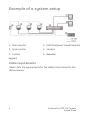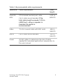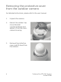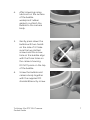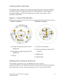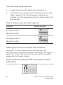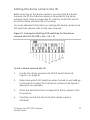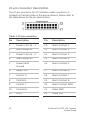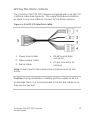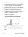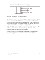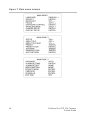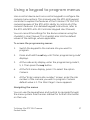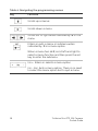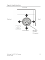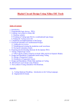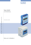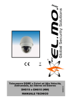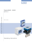
1
GE Security TruVision Mini PTZ 12X Camera Pocket Guide P/N 1069516 • REV A • ISS 01DEC09 Copyright © 2009 GE Security, Inc. Content Introduction 2 Package contents 2 Installation environment 2 Example of a system setup 4 Cable requirements 4 Removing the protective cover from the outdoor camera 6 Setting up the camera 8 Camera DIP switches 9 Setting the camera protocol 9 Setting the communication DIP switches 10 Setting the dome camera site ID 11 22-pin connector description 12 Wiring the dome camera 13 Main menu overview 15 Using a keypad to program menus 17 TruVision Mini PTZ 12X Camera Pocket Guide 1 Introduction This pocket guide provides basic information on setting up and using the TruVision Mini PTZ camera. Package contents The TruVision Mini PTZ camera is shipped with the following items: Dome camera and 4.7” bubble Mounting accessories (hard ceiling mount, plastic fixing plate, and screws) I/O interface cable for power, video, alarms, and serial data TruVision Mini PTZ 12X Camera pocket guide TruVision Mini PTZ 12X Camera user manual (on CD) Installation environment When installing your camera, consider these factors: • Handling: Handle the camera carefully. Avoid striking, shaking, etc. Improper handing or storage could damage the camera. • Electrical: Install electrical wiring carefully. It should be done by qualified service personnel. The input electricity to the unit has a tolerance of 24 VAC ± 10%. Do not overload the power cord or adapter. 2 TruVision Mini PTZ 12X Camera Pocket Guide • Ventilation: Ensure that the location planned for the installation of the camera is well ventilated. • Temperature: Do not operate the camera beyond the specified temperature, humidity or power source ratings. The operating temperature of the indoor camera is between 0°C to 50°C (32°F to 122°F) and that of the outdoor camera is between -30°C to 50°C (-22°F to 122°F). Humidity is below 90%. • Moisture: Do not expose the indoor camera to rain or moisture, or try to operate it in wet areas. The indoor camera is designed for indoor use or locations only where it is protected from rain and moisture. Turn the power off immediately if the camera is wet and ask a qualified service person for servicing. Moisture can damage the camera and also create the danger of electric shock. • Cleaning: Clean only with a dry cloth. If the dirt is difficult to remove, use a mild detergent and wipe gently. • Protect from strong light: Never face the camera towards the sun. Do not aim the camera at bright objects. Whether the camera is in use or not, never aim it at the sun or other extremely bright objects. Otherwise, the camera may be smeared or damaged. • Servicing: Do not attempt to service this unit yourself. Any attempt to dismantle or remove the covers from this product will invalidate the warranty and may also result in serious injury. Refer all servicing to qualified service personnel. TruVision Mini PTZ 12X Camera Pocket Guide 3 Example of a system setup 1. Main monitor 4. DVR /Multiplxer/ Quad/ Switcher 2. Spot monitor 5. Camera 3. Control 6. Repeater keypad Cable requirements Table 1 lists the requirements for the cables that connect to the dome camera. 4 TruVision Mini PTZ 12X Camera Pocket Guide Table 1: Recommended cable requirements Operation Cable requirement Max. length Data (RS485) STP (shielded twisted-pair) cable 1219 m (4000 ft) Video 75 ohm coaxial cable with BNC ends 486 m (1600 ft) Alarm Cat-5 cable recommended. 381 m (1250 ft) Power 24 VAC cable. To determine the size of cable needed for individual applications, please refer to the user manual. Cat-5 cable recommended. If the total cable length exceeds 1219 m (4000 feet), using a repeater to maintain the signal is recommended. TruVision Mini PTZ 12X Camera Pocket Guide 5 Removing the protective cover from the outdoor camera For detailed instructions, please refer to the user manual. 1. Unpack the camera. 2. Detach the outdoor top mount bracket counterclockwise and detach it from the main camera housing. 3. Remove the protective cover and PE sheet from the camera. 6 TruVision Mini PTZ 12X Camera Pocket Guide 4. After smearing some lubricant on the surface of the bubble waterproof rubber gasket, re-attach the bubble to the camera body. 5. Gently press down the bubble with two hands on the side of it. Make sure the two slotted screws and the screw hole on the bubble align with the three holes on the camera housing. DO NOT press on the top of the bubble. 6. Screw the bubble and camera body together with the supplied M3 standard/security screw. TruVision Mini PTZ 12X Camera Pocket Guide 7 7. Further secure the bubble by turning the two slotted screws counterclockwise so that they touch the dome camera housing. 8. Set the DIP switches. Setting up the camera To quickly put the Mini PTZ 12X camera into operation 1. Configure the camera’s DIP switches, which are located on the top of the camera. 2. Set the camera communication protocol. 3. Set the RS-485 communication DIP switch. 4. Set the camera ID. 5. Wire the camera. 6. Connect the camera to a monitor. 7. Mount the camera to the ceiling. See the user manual for information. 8. Program the camera. 8 TruVision Mini PTZ 12X Camera Pocket Guide Camera DIP switches Configure the camera’s ID and communication protocol before connecting the analog camera to other devices. See Figure 1 for the location of the DIP switches in both the indoor and outdoor cameras. Figure 1: Camera DIP switches Indoor camera Outdoor camera A. Dome camera protocol DIP switches D. 22-pin connector B. RS-485 communication DIP switches C. None E. Dome camera site ID DIP switch F. Reserved G. Reserved Setting the camera protocol The dome camera can use different protocols for communication. To select a protocol, you must set the protocol DIP switches to the correct sequence of 1s (on) and 0s (off). TruVision Mini PTZ 12X Camera Pocket Guide 9 To set the dome camera protocol 1. Locate the protocol DIP switch block (A, Figure 1). 2. Set the DIP switch sequence for the desired protocol. See Table 2 below for the most frequently used protocol settings. For other supported protocols, please refer to the user manual. Table 2: Dome camera protocols supported Protocol Switch position GE Impac RS-485 (Baud rate: 9600) GE Digiplex RS-422 (Baud rate: 4800) Setting the communication DIP switches See Figure 1 for the location of the communication DIP switches. The RS-485 default setting is half-duplex (see Figure 2 below.) For further information on the other options available, please refer to the user manual. Figure 2: Default setting of RS-485 communication switch (half-duplex) 10 TruVision Mini PTZ 12X Camera Pocket Guide Setting the dome camera site ID Before turning on the dome camera, you must set the dome camera site ID. Each dome camera connected to the same network must have a unique site ID. Use the 10-bit DIP switch to set the dome camera site’s ID setting. For more detailed information on setting the dome camera site DIP switches, please refer to the user manual. Figure 3: Example of setting DIP switches for the dome camera site ID 210 (128 + 64 + 16 + 2) To set a dome camera site ID 1. Locate the dome camera site ID DIP switch block (E, Figure 1 on page 9). 2. Determine which DIP switches when turned on will add up to the site ID number for that dome camera. See Figure 3 above for an example. 3. Place the switches that correspond to those values in the On position. 4. Carefully record the site ID of each dome camera installed. TruVision Mini PTZ 12X Camera Pocket Guide 11 22-pin connector description The 22-pin connector for I/O interface cable connection is located on the back plate of the dome camera. Please refer to the table below for the pin descriptions. Table 3: 22-pin connector Pin Description Pin Description 1 Power In AC 24 – 1 12 Alarm Contact 1 2 Alarm Relay NC 13 Alarm Contact 2 3 Power In AC 24 – 2 14 Alarm Contact 3 4 Alarm Relay NO 15 Alarm Contact 4 5 Power Earth Ground 16 Alarm Contact 5 6 Relay Com 17 Alarm Contact 6 7 Control T+ 18 Alarm Contact 7 8 Control R- 19 Alarm Contact 8 9 Control T- 20 Alarm Contact GND 10 Control R+ 21 Video GND 11 ISOG 22 Video POS 12 TruVision Mini PTZ 12X Camera Pocket Guide Wiring the dome camera The TruVision Mini PTZ 12X Camera is shipped with a 24 VAC I/O interface cable (see Figure 4). This cable facilitates installation as there is only one cable to connect to the dome camera. Figure 4: 24 VAC I/O interface cable 1. Power input cable 2. Video output cable 3. Alarm cable 4. RS-485 serial data connector 5. 22-pin connector (to camera) Note: Power input to the camera has a tolerance of 24 VAC ±10%. Caution: During installation carefully pull the cables so as not to damage them. It is recommended to fasten the cables once they are connected. TruVision Mini PTZ 12X Camera Pocket Guide 13 To wire the dome camera 1. Connect the 22-pin connector of the I/O interface cable to its connector in the base of the dome camera. See Figure 1 for its location. 2. Connect the crimp-on BNC connector of the video output to the coaxial video cable of a monitor or DVR. 3. Connect the control keyboard to the dome camera through the serial terminal block. 4. Connect the alarm cable to a dry contact. For example, a PIR detector, or an access control system. 5. Connect the RS-485 serial data connector to the DVR/keypad, as shown below. Figure 5: 2-wire connection from a DVR/control keypad/PC to the dome camera 6. Connect the power cable to the power source. As soon as the dome camera is connected, it is operational. Note: The ground wire must be inserted into the center pin of the power input terminal block. See Figure 6 on page 15. 14 TruVision Mini PTZ 12X Camera Pocket Guide Figure 6: Ground wire for power input Main menu overview The dome camera is programmed through the on-screen (OSD) menus. To access the OSD menus, you must open the main menu. The main menu, which appears over three screens, lets you set up the dome camera or change the default settings to suit your installation. See Figure 7 on page 16. Note: The OSD menu can be pre-programmed to time-out after certain number of minutes of inactivity. All configuration changes made are automatically saved. Please refer to the user manual for detailed information on programming the dome camera and on-screen displays. TruVision Mini PTZ 12X Camera Pocket Guide 15 Figure 7: Main menu screens 16 TruVision Mini PTZ 12X Camera Pocket Guide Using a keypad to program menus Use a control device such as a control keypad to configure the camera menu options. This manual uses the KTD-405 keypad controller to explain the features of the TruVision PTZ Mini 12X camera because of the KTD-405’s ability to control all of the camera’s features. (For detailed keypad instructions, refer to the KTD-405/KTD-405-2D Controller Keypad User Manual.) You can record the settings for the dome cameras using the checklist in User Manual. This checklist also lists the default values of the settings, where applicable. To access the programming menus 1. Switch the keypad to the camera site you want to program. 2. Press and hold the set key until “Enter programming code” displays. 3. At the code entry display, enter the programming code 9, 5, 1. Then press the seq button. 4. At the first menu display, press 3 to select the option Camera. 5. At the “Enter camera site number” screen, enter the site number of the camera you wish to program. Camera default value is 1. The Main Page 1 menu appears. Navigating the menus You can use the keypad keys and joystick to navigate through the menu system. See the user manual for further information on their use. TruVision Mini PTZ 12X Camera Pocket Guide 17 Table 4: Navigating the programming menus Key Function Scrolls up a menus Scrolls down a menu Scrolls left or right when indicated by in the menu Enters or exits a menu or submenu when indicated by in a menu option. When a menu has , scroll left and right to select a menu function and then press the set key to enter the submenu. Iris +: Enters or selects a menu option Iris -: Esc. Exits a menu option. There is no need to select the menu option Exit to quit a menu. 18 TruVision Mini PTZ 12X Camera Pocket Guide Figure 8: Joystick motion Scroll up Next Previous Scroll down TruVision Mini PTZ 12X Camera Pocket Guide Edit (turn joystick clockwise) 19