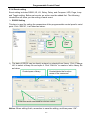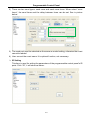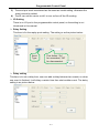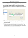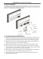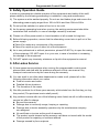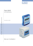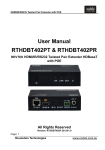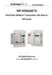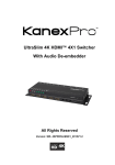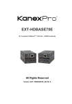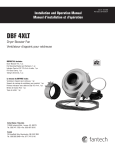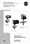
1
Programmable Control Panel Wall Plate All Rights Reserved Version: Programmable Control Panel 2013V1.2 Programmable Control Panel NOTICE: Please read this user manual carefully before using this product. This manual is for operation instruction only, not for any maintenance usage. The functions described in this version are updated till May 2013. Any changes of functions and parameters since then will be informed separately. Please refer to the dealers for the latest details. All rights reserved. No part of this publication may be copied or reproduced without permission. All product function is valid till 2013-05-28. Update History Version 1.0 1.1 Date 2012.02.25 2013.05.28 Update Content First version. Modified the system diagram. Programmable Control Panel Table of Contents 1. Introduction ................................................................................................................. 1 1.1 Introduction to the Programmable Control Panel ............................................... 1 1.2 Package Contents.............................................................................................. 1 2. Features ...................................................................................................................... 1 3. Specification ................................................................................................................ 2 4. Connection Introduction .............................................................................................. 2 4.1 Interfaces Introduction ....................................................................................... 2 4.2 Connection of Programming and Looping ......................................................... 3 5. System Operations...................................................................................................... 5 5.1 Front Panel Introduction..................................................................................... 5 5.2 USB Driver Installation ....................................................................................... 5 5.3 Software Programming ...................................................................................... 5 5.3.1 Main Menu ............................................................................................... 6 5.3.2 Panel/Key setting ..................................................................................... 8 5.3.3 Action list ............................................................................................... 10 5.3.4 Event setting .......................................................................................... 11 5.3.5 Event List ............................................................................................... 19 6. System Diagram........................................................................................................ 20 7. Troubleshooting & Maintenance ............................................................................... 20 8. Safety Operation Guide............................................................................................. 21 9. After-sales Service .................................................................................................... 21 Programmable Control Panel 1. Introduction 1.1 Introduction to the Programmable Control Panel The KanexPro WP-CONTROLS is a programmable control panel designed to control your Audio Video devices using IR, RS-232 & RS-485. Every button is programmable and works either individually or together. The programmable control panel consists of programmable 3xRS232, 1xRS485, 3xInfrared & 2xRelay, and 1xmini USB for programming. Please note: The RS-232 (1) and IR (2) share the same port, and cannot be used at the same time. Also, RS232 (2) and IR3 share the same port, and cannot be used at the same time. Control KanexPro products such as switchers, scalers and extender, as well as third party devices such as projectors, screens and much more. It is an easy-to-use control device for conference and boardrooms, classrooms and lecture halls. 1.2 Package Contents Ø Ø Ø Ø Ø Ø 1 x Programmable Control Panel 1 x Power adapter (DC 12V) 4 x Captive screw connector 3 x IR emit probe 1 x Button labels 1 x User Manual Note:Please confirm if the product and the accessories are all included, if not, please contact with the dealers. 2. Features l Every button can be programmed to send the bi-direction RS232 and RS485 commands simultaneously to control third party devices l Every button can be programmed to send the infrared code, control the relay, to let them work simultaneously to control the third party devices l Every button is built in the infrared code and RS232 code learning function, and baud-rate setting l ID looping function l Up to 99 units programmable control panels can be looped and controlled together by ID detection l Programmed by USB or RS232, working with the PC software (PS-WP). l Crystal and backlit buttons with easy user-friendly customizable changeable labels l The backlit brightness is controllable l Mini USB connector l Décora style wall plate l Dimensions: 11.4cm long and 7cm wide 1 Programmable Control Panel 3. Specification Specification PS-WP Baud Rate And Protocol Temperature 3 x RS232, 1 x RS485, 3 x Infrared, 2 x Relay 9600 baud, 8 data bits, 1 stop bit, no parity -20 ~ +70°C 20Hz ~20KHz Humidity 10% ~ 90% Power Supply 100VAC~240VAC, 50/60 Hz Case Dimensions 114x70 x28mm Power Consumption Product Weight Program Port Serial Control Port Software Frequency Response USB or RS232 RS232 Output Port 1W 0.15kg 4. Connection Introduction 4.1 Interfaces Introduction The programmable control panel has various ports in the rear panel, including Lopping port, RS232 port, RS485 port, IR port, Relay port and Power port. Below is the introduction: ① This port includes two parts: One part is RS232 (2)/IR3, it can be used for control other devices or looping output. RS232 (2) and IR3 share the same port, the detailed use depends on the setting of PS-WP. 2 Programmable Control Panel Other part is RS232 (3), it can be used for control other devices or looping output, or connect with PC. These two parts share the same grounding. ② This port includes: RS232 (1)/IR2, IR1 and RS485. a) RS232 (1)/IR2: share the same port; the detailed use depends on the setting of PS-WP. When be used as RS232, it is unidirectional transmission, transmit data but without receive. b) IR1: for control other devices, it can be programmable by the PS-WP. c) RS485: the RS485 can be programmed as different commands and control the device with RS485 port. The command of RS485 is the same as RS232 (1). ③ Low-Voltage relay ports: set the relay on/off by software PS-WP. ④ Power connector: 12VDC. Be sure that the “+” and “-” never be mixed or wrong connection. Infrared sensor port: receive and learn the IR code, to build the IR database. ⑤ ⑥ Mini USB Connector: Communicate with PC, which uses PS-WP to program the buttons. Transmit the infrared data when learning IR (Optional). Note: When use this USB port to program the control panel’s buttons, the available COM port number should not be more than 10. 4.2 Connection of Programming and Looping The programmable control panel can be connected to the computer for programming, to default the functions of every button. It can be connected by USB or RS232, working with the PS-WP software. It is shown as below: Programming Connection 3 Programmable Control Panel Several pieces programmable control panels can be also looped to be a system, for control more devices. It is looped by the inter RS232 setting. Please check the demo picture as below: Several programmable control panels Looping connecting After connect the programmable control panels as above, and then we should set the ID of each programmable control panel by PS-WP. The ID number is from 01 to 99, and it also is the class of the programmable control panel in the loop, different programmable control panels should set to different ID. After connections finish, we can set the control modes by PS-WP. For detailed connecting, please check the picture below: Last class … Second class Detailed looping connecting 4 Programmable Control Panel 5. System Operations 5.1 Front Panel Introduction Crystal and luminescent, programmable buttons: Every button can be programmable with the software PS-WP. Connect the PC via USB or RS232. And every label inside the button can be changeable. You can choose the label you need and change it very easily like below: (For the specific transparent paper table, please contact the local distributor or reseller for it) 5.2 USB Driver Installation There are USB driver file and PS-WP software in the disk. The PS-WP can run directly without installation. But when connect the programmable control panel with PC by USB; it may need to install the USB driver. Use the driver file to install the driver of USB; we can use USB to program the programmable control panel. 5.3 Software Programming You can use this software PS-WP to easily set every button of the programmable control panel. 5 Programmable Control Panel After connect the programmable control panel with PC by USB or RS232, we can open the PS-WP to program the buttons for controlling. The main window of PS-WP has five parts: main menu, panel (button) setting, event setting, action list and event list. In this manual we will take WP8-V for example, to show the uses of all functions. The main window of PS-WP is as below: We will introduce all the configurations one by one. 5.3.1 Main Menu The main menu includes file management, system model, connection type and help. 1) File management: Open/Save/Save as a configuration. After program, user can save the configuration to a file, so that you can use the same configuration next time. 2) System model: includes WP8-H, WP8-V, WP19R etc, and the buttons interface view is different with different models. The pictures below show the differences between WP8-V and WP8-H. 6 Programmable Control Panel NOTE: When select the model, it will pop up “Output Port Selection” dialog, user can select different RS and IR types, depend on the uses of the two-shared ports. The dialog is as the picture below: The output port set in PS-WP and the port used in the programmable control panel is corresponding. And there are four output types. They are showed as below form (“√” means port is available): 7 √ √ √ √ √ √ RS485 √ √ √ RS232 (3) √ √ IR3 √ RS232 (2) √ √ √ √ IR2 IR1 RS232 (1)(2) RS232 (2), IR2 RS232 (1), IR3 IR2, 3 RS232 (1) Output port of the Panel Output mode of PS-WP √ √ Programmable Control Panel 3) Connection type: the instructions are in the picture below: 1:Com, connect by serial port. 2:USB, connect by mini USB. 3:Disconnect, disconnect the connection. 4:Upload: upload the programmed data to the programmable control panel. It will clear all the old data in the programmable control panel. 5:Clear, clear the data in the programmable control panel. The functions of the programmable control panel’s buttons will be available only after the programmed data is uploading successfully. 4) Help: Show the information of PS-WP. 5.3.2 Panel/Key setting There are three different colors of keys in the panel set of PS-WP. Add a key action to action list, then add events to this action, make this action will execute the events. Here take WP8-V for example, to introduce the uses of different buttons: 1. White keys: keys 1-8, correspond to the buttons on the programmable control panel. Click the key, it will pop up dialog as below: 8 Programmable Control Panel Key Action Type: 1. Press: Execute events when press button. 2. Release: Execute events when release button. 3. Page: Built-in most 4 actions, actions need to be switched by other buttons, press to execute. 4. Toggle: Built-in most 4 actions, actions will loop run when press. Actions can also be switched by other buttons, press to execute. When select the type “Toggle”, the setting interface is as below: The toggle class is the action loop class, depends on the numbers of looped actions. When the class is 2, there are two actions in the toggle. And so on. 2. Blue Keys: Keys 9-32, all are virtual keys, used in the loop function. When use the loop function, the ID must be set, the ID can be 1 to 99. Press “add” will add the button to action list. 9 Programmable Control Panel 3. Yellow Keys: Keys 33-36, all are virtual keys. Key 33 and 34 are for I/O control, which is not supported with the programmable control panel. Key 36 is a start action, if add events to this action, when the programmable control panel is power on, it will execute the events in this action. Key 35 is delay button, there are three time slots can be set. See in the picture below: The time is counted from the programmable control panel start. When come to time1, the programmable control panel will execute the events in time1. Then recount from time2, and then time3. Example: Set time1 to 5 minutes, and time2 to 3 minutes; add event1 to time1 and event2 to time2. When the unit starts, it will execute event1 after 5 minutes, and then execute event2 after 8 minutes. 5.3.3 Action list Action list shows all the set actions. An available action must be added to the list. The action list is as the picture below: Delete all actions. Delete a selected action. Refresh, delete all the actions that with no event. 10 Programmable Control Panel 5.3.4 Event setting Event setting includes RS232, IR, I/O, Relay, Delay, and Compare, LED, Page, Loop and Toggle setting. Before set events, an action must be added first. The following introduction will show you the setting of each event: Ø RS232 Setting This item is used for setting the parameters of the programmable control panel’s serial ports. Click “RS232”, it will show as below: Send Type Send Port 1) The data of RS232 can be directly entered or selected from library. Click “Change Lib” to select a library file and open it. Click “Edit Lib” to create or edit a library file as below: Create/open a library Create/delete the function name of the command Enter the serial command for device control. Notice: When editing finish, remember to save the editing, and then press “OK”. 11 Programmable Control Panel 2) There are two send types: send once and send more times. When select “more times”, the send times and the delay between times can be set. See in picture below: 3) The send port must be selected as the same as model setting, otherwise the event cannot be added. 4) User can set the event name. It is optional function, not necessary. Ø IR Setting This item is used for setting the parameters of the programmable control panel’s IR ports. Click “IR”, it will show as below: 12 Programmable Control Panel 1) The data of IR need to be selected from library. Click “Change Lib” to select a library file and open it. Click “Edit Lib” to create or edit a library file as below: Create/open a library Create/delete/rename the function name of the IR data Select a function, and then click “learn”, press the IR remote button to send the IR code to infrared sensor port, it will refresh the IR data. Follow the same steps can learn any function of the remote buttons. Notice: When editing finish, remember to save the editing, and then press “OK”. 2) There are two send types: send once and send more times. When select “more times”, the send times and the delay between times can be set. See in picture below: 13 Programmable Control Panel 3) The send port must be selected as the same as model setting, otherwise the event cannot be added. 4) The IR can set the carrier on/off, to turn on/turn off the IR sending. Ø I/O Setting There is no I/O port in the programmable control panel, so the setting is not introduced in this manual. Ø Relay Setting This item is for the replay ports setting. The setting is as the picture below: Send Type Port Action: “On” for connected, “Off” for disconnected. Ø Delay setting This item is to set a delay time, user can add a delay between two events; so when one event is finished, it will delay a certain time then start another event. The delay setting is as picture below: 14 Programmable Control Panel Ø Compare Setting This item is used for compare the feedback of RS232 commands. When the programmable control panel sends a RS232 command to the controlled device, the device will send back a feedback. If we add the correct feedback in the data, the programmable control panel will compare it with the feedback received from controlled device, to verify the command is work or not. The compare setting is as the picture below: Enter the compare commands, don’t miss any character. 1) The send port must be selected as the same as model setting, otherwise the event cannot be added. And port 1 cannot be used for compare, for there is no a receive pin in this port. 2) User can set the event name; it is optional function, not necessary. 3) For the events in one event list have priority, from top to bottom, so that the compare function can be used in action which with three or more events. When send a serial command, we can add a compare then other events. If the compare is incorrect, the event behind compare will not be executed. 15 Programmable Control Panel Ø LED setting This item is used for set the button LEDs in the programmable control panel to turn on/off. The setting is as below: Ø Page setting White buttons can be set to type “page” that include four actions. To change different actions, it will need other white buttons to active the page action number. Here take a example to show you the use of this function: 1) Take button1 for example: click key1 and select the action type “page”, add the four actions to the action list. Then add other four buttons “press” action to the list (here take keys 5-8 for example): 16 Programmable Control Panel 2) In event setting, we add four different events to the four page actions of key1, and the four other keys will be added the page event to each of them as below: Then set the “page” event to make four “press” actions to active the four page number: key5-num1, key6-num2, key7-num3 and key8-num4. It will perform like this: a) When press the button5 and then button1, the button1 will execute the event of num1, press button1 more times it will execute num1 more times; b) When press the button6 and then button1, the button1 will execute the event of num2, press button1 more times it will execute num2 more times; c) When press the button7 and then button1, the button1 will execute the event of num3, press button1 more times it will execute num3 more times; d) When press the button8 and then button1, the button1 will execute the event of num4, press button1 more times it will execute num4 more times. 17 Programmable Control Panel Ø Loop Setting This item is used for looping the programmable control panel. When use the loop function, the ID of each programmable control panel must be set. Ø Toggle Setting The toggle setting is as the picture below: The setting steps of toggle are similar with the page setting. But toggle performs differently, for the actions in it are loop running, it will perform as below (take the same example like page function): a) When press the button5 and then button1, the button1 will execute the event of num1, press button1 more times it will execute num2, then num3->num4->num1 and so on. 18 Programmable Control Panel b) When press the button6 and then button1, the button1 will execute the event of num2, press button1 more times it will execute num3, then num4->num1->num2 and so on. c) When press the button7 and then button1, the button1 will execute the event of num3, press button1 more times it will execute num4, then num1->num2->num3 and so on. d) When press the button8 and then button1, the button1 will execute the event of num4, press button1 more times it will execute num1, then num2->num3->num4 and so on. 5.3.5 Event List The event list shows all events of the selected action, and for each action of the programmable control panel, the most events can be added are ten. The executing priority is from 1 to 10, see the picture below. If there is an event execute incorrectly, all the events behind it will not be executed. 19 HDMI/IR/RS232 Twisted Pair POC Extender 6. System Diagram The programmable control panels can active different ports at one time. It means every button can send the RS232 and RS485 commands, IR code and control the relay at the same time. The demo system diagram as below: 7. Troubleshooting & Maintenance 1) When the control panel cannot work, please check and make sure the power cord connection is well, plug cannot be mixed or connect wrong. Then restart, if still not work, the control panel may be broken. Please send it to the dealer for repairing. 2) When USB cannot open or without response, please make sure the USB driver is installed correctly, and then reconnect the USB cable. 3) When uploading the USB cannot be found, please restart the software or panel. 4) When the LED of a button cannot be lighted, please check if there is a compare event in this button. If yes, delete the compare and try again. If still not work, the LED may be broken. Please send the unit to dealer for repairing. 5) When serial commands sending without function executed please check the baud rate and make sure is correct, and the serial connection is well. 6) If the controlling queue is confused when use loop function, please reboot the programmable control panel. Programmable Control Panel 8. Safety Operation Guide In order to guarantee the reliable operation of the equipments and safety of the staff, please abide by the following proceeding in installation, using and maintenance: 1) The system must be earthed properly. Do not use two blades plugs and ensure the alternating power supply ranged from 100v to 240v and from 50Hz to 60Hz. 2) Do not put the switcher in a place of too hot or too cold. 3) As the power generating heat when running, the working environment should be maintained fine ventilation, in case of damage caused by overheat. 4) Please cut off the power switch in humid weather or left unused for long time. 5) Before following operation, ensure that the alternating current wire is pull out of the power supply: l Take off or reship any components of the equipment. lTake off or rejoin any pin or other link of the equipment. 6) As to non-professional or without permission, please DO NOT try to open the casing of the equipment, DO NOT repair it on your own, in case of accident or increasing the damage of the equipment. 7) DO NOT splash any chemistry substance or liquid in the equipment or around. 9. After-sales Service 1) If there appear some problems when running the programmable control panel, please check and deal with the problems reference to this user manual. Any transport costs are borne by the users during the warranty. 2) You can email to our after-sales department or make a call, please tell us the following information about your cases. l Product version and name. l Detailed failure situations. l The formation of the cases. 3) We offer products for all three-year warranty, which starts from the first day you buy this product (The purchase invoice shall prevail). 4) Any problem is same with one of the following cases listed; we will not offer warranty service but offer for charge. l Beyond the warranty. l Damage due to incorrectly usage, keeping or repairing. l Damage due to device assembly operations by the maintenance company non-assigned. l No certificate or invoice as the proof of warranty. l The product model showed on the warranty card does not match with the model of the product for repairing or had been altered. l Damage caused by force majeure. 21 Programmable Control Panel 1. Warranty KanexPro® warrants that (a) its products (the “Product”) will perform greatly in agreement with the accompanying written materials for a period of 36 months from the date of receipt (3 years) and (b) that the product will be free from defects in materials and workmanship under normal use and service for a period of 3 years. B. CUSTOMER REMEDIES KanexPro’s entire liability and Customer’s exclusive remedy shall be, at KanexPro option, either return of the price paid for the product, or repair or replacement of the Product that does not meet this Limited Warranty and which is returned to KanexPro with a copy of customers’ receipt. This Limited Warranty is void if failure of the Product has resulted from accident, abuse, or misapplication. Any replacement Product will be warranted for the remainder of the original warranty period of 3 years, whichever is longer. C. NO OTHER WARRANTIES TO THE MAXIMUM EXTENT PERMITTED BY APPLICABLE LAW, KANEX DISCLAIMS ALL OTHER WARRANTIES, EITHER EXPRESS OR IMPLIED, INCLUDING, BUT NOT LIMITED TO IMPLIED WARRANTIES OF MERCHANTABILITY AND FITNESS FOR A PARTICULAR PURPOSE, WITH REGARD TO THE PRODUCT AND ANY RELATED WRITTEN MATERIALS. THIS LIMITED WARRANTY GIVES CUSTOMERS SPECIFIC LEGAL RIGHTS. CUSTOMERS MAY HAVE OTHER RIGHTS DEPENDING ON THE JURISDICTION. D. NO LIABILITY FOR DAMAGES TO THE MAXIMUM EXTENT PERMITTED BY APPLICABLE LAW, IN NO EVENT SHALL KANEX BE LIABLE FOR ANY DAMAGES WHATSOEVER (INCLUDING WITHOUT LIMITATION, SPECIAL, INCIDENTAL, CONSEQUENTIAL, OR INDIRECT DAMAGES FOR PERSONAL INJURY, LOSS OF BUSINESS PROFITS, BUSINESS INTERRRUPTION, LOSS OF BUSINESS INFORMATION, OR ANY OTHER PECUNIARY LOSS) ARISING OUT OF THE USE OF OR INABILITY TO USE THIS PRODUCT, EVEN IF KANEX HAS BEEN ADVISED OF THE POSSIBILITY OF SUCH DAMAGES. 22 Programmable Control Panel Brea, California KanexPro.com MPN: WP-CONTROLS KanexPro is a trademark of Apogee Inc., registered trademarks in the U.S 23 Programmable Control Panel 24