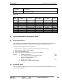
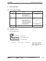
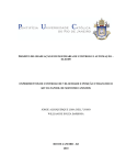
1
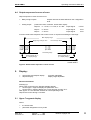
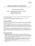
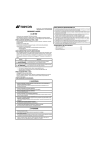
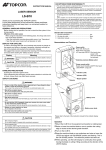
Operating Instructions
DMP 96 A
Single-channel controller
Two-point controller
Continuous-action controller
with one limit-value contact
Program versions:
020H0
020H1
020H2
020H3
020H4
020H5
020H6
020H7
020H8
°C
1
2
4
3
K1
K2
Ist
Soll
P
DMP 96 A
Before connecting the regulator it is essential to read
this Manual and follow it's instructions.
(Subject to technical changes)
DOLD GMBH . Blumenstrasse 33 . 70736 Fellbach . Germany
Phone +49 (0)711/95152-0 . Fax +49 (0)711/95152-19 . [email protected] . www.dold-regler.de
DOLD GMBH
Operating instructions DMP 96 A
Contents
1. INSTALLING THE CONTROLLER:........................................................................ 4
1.1 Directions for installation ...............................................................................................................4
1.2 Identification plate:.........................................................................................................................5
1.3 Connecting the controller: .............................................................................................................6
1.3.1 Auxiliary power: ..........................................................................................................................6
1.3.2 Terminal connection diagram:....................................................................................................6
1.4 Mechanical Data:...........................................................................................................................6
2. TECHNICAL DATA, INPUTS:................................................................................. 7
2.1 Analog inputs:................................................................................................................................7
2.1.1 Technical Data, inputs:...............................................................................................................7
2.1.2 Error-handling at input: ...............................................................................................................8
2.2 Digital inputs: .................................................................................................................................8
3. CONTROL RESPONSE: ........................................................................................ 8
3.1 Controller function: ........................................................................................................................8
3.1.1 Two-point controller:...................................................................................................................9
3.1.2 Continuous-action controller:......................................................................................................9
3.1.3 Three-point response: ................................................................................................................9
3.2 Actuator function: ..........................................................................................................................9
4. OUTPUTS: ............................................................................................................ 10
4.1 Potential-free relay contacts, make contact: ...............................................................................10
4.2 Logic output (optional): ................................................................................................................10
4.3 Analog output: .............................................................................................................................10
4.3.1 Technical data, analog output: .................................................................................................10
4.4 Output responses in cases of error: ............................................................................................11
5. DISPLAY:.............................................................................................................. 11
5.1 Upper 7-segment display ............................................................................................................11
5.2 Lower 7-segment display.............................................................................................................12
5.3 LED's: ..........................................................................................................................................12
6. EXPLANATIONS OF SYMBOLS:......................................................................... 12
DMP 96 A
H0e020bA4.doc
Version:
020
Edition: 07.11.2006
Number of pages: 26
2
DOLD GMBH
Operating instructions DMP 96 A
7. OPERATION:........................................................................................................ 13
7.1 Setting parameters on the various levels: ...................................................................................13
7.2 The various levels: ......................................................................................................................14
7.3 Setting the setpoint:.....................................................................................................................14
7.3.1 Setting the setpoint via the operator level: ...............................................................................14
7.3.2 Setting the setpoint level via the setpoint entry level: ...............................................................15
7.4 The configuration level: ...............................................................................................................15
7.4.1 Switching response of the K 2 limit-value contact: ...................................................................19
7.5 The parameterization level: .........................................................................................................19
7.6 The self-optimization level:..........................................................................................................20
7.6.1 Monitoring the optimization process:........................................................................................22
7.7 The information level: ..................................................................................................................23
8. LINE COMPENSATION, ZERO-POINT OFFSET:................................................ 24
8.1 Line compensation: .....................................................................................................................24
8.2 Zero-point offset: .........................................................................................................................24
9. ERROR MESSAGES: ........................................................................................... 25
9.1 Error messages (display): ...........................................................................................................25
10. PROGRAM VERSION: ....................................................................................... 25
11. IMMUNITY: ......................................................................................................... 26
DMP 96 A
H0e020bA4.doc
Version:
020
Edition: 07.11.2006
Number of pages: 26
3
DOLD GMBH
1.
Operating instructions DMP 96 A
Installing the controller:
1.1 Directions for installation
Important:
These directions for the installation of
DOLD devices have to be adhered to:
If these directions are not adhered to the device may not work accurately, be destroyed
or it may result in data being lost.
Read all directions carefully before connecting the device.
Connection to be carried out only by experts.
This device is not a safety device. Safety devices have to be installed according to the relevant
directions for use.
Check if the power-supply voltage corresponds to rated voltage indicated on the identification
plate before connecting and putting the device into operation. Fluctuations in the main voltage
are only admissible within the indicated limits (specifications/identification plate).
The described device is designated for the installation of switchboards.
Electrical connections are to be carried out according to the connecting plan and the directions
of the local electric supply company or the relevant regulations of the VDE respectively.
Other consumers must not be connected to the mains terminals.
In the event of mains interruptions, which lead to a malfunctioning of the device, relevant measures must be taken to avoid interruptions or interruptions must be filtered out by an external hum
eliminator. The device is equipped with an internal hum eliminator.
On installation the sensor lines have to be shielded. The screen must be single-ended. With regard to thermoelement pick-ups the compensating lead has to be laid as far as the control terminals. The device and inductive consumers as well as sensor lines/signal lines and high tension lines have to be placed in such a way that any mutual interference is excluded (placed
separately; not parallely laid). go-and-return lines should be laid parallely and, if possible,
twisted.
Non-insulated sensors of a multi-channel control have to be adjusted to the same potential
(max. potential difference: + 3.5 V eff.). Otherwise insulated sensors must be used (Warning:
Ceramics insulations (Al-Oxide) can be conducting >400 °C).
Post-connected contactors have to be equipped with RC protective allocations according to the
manufacturer's instructions. If an internal protective allocation is mentioned in the connection
plan of the device this has to be taken into account in the event of external allocation. If external
allocation is missing short-term voltage peaks may result which lead to faster contact wear and
may cause interference.
The preadjustment of all parameters has to be checked during operation and adjusted to the local conditions (installation)! Wrongly adjusted parameters may cause serious malfunctions!
Not all controlled systems can be controlled by parameters measured by means of selfoptimising; therefore, on principle, control response is to be checked for stability.
DMP 96 A
H0e020bA4.doc
Version:
020
Edition: 07.11.2006
Number of pages: 26
4
DOLD GMBH
Operating instructions DMP 96 A
The load circuits of the relays have to be protected against excessive currents in order to avoid
the relay contacts becoming welded together.
The device must not be installed in an ex-area.
If used for purposes other than originally intended the device may be damaged and cause damage to connected installations.
The life time of the relays is limited to 106 switching cycles at a load of 500 VA. Thus it is to a
high degree dependent on the frequency of switching cycles.
Time per switching cycle
Time after which 106 switching cycles are reached
(operation: 8 hours/day at a load of 500 VA)
120 s
about 11.4 years
60 s
about 5.7 years
30 s
about 2.8 years
This table is invalid for Solid-State-Relay.
At low loads life time increases with regard to the values indicated in the table.
The device is to be protected against moisture (especially condensing moisture) and excessive
contamination. If this is not assured the device is liable to malfunctions.
Unplug connecting plugs only longitudinally to plug direction. Under no circumstances must the
connecting plugs be plugged in or out obliquely!
Furthermore care must be taken that the surrounding temperature corresponds to the values
shown in the specifications. Sufficient air circulation must be provided.
These operating instructions do not contain all directions to regulations, standards etc. which
become effective when using this device in connection with other installations. These regulations, standards etc. must be ascertained and abided to by the purchaser.
1.2 Identification plate:
The following information is
important and should be given
whenever you have any technical
questions:
Type of controller
Factory number
Program version
Model number
DMP 96 A
ASP 675XXX
Operating voltage: XXX V +/-10%
Switching capacity: 500 VA at 230 V AC
Factory number:
Input:
Logic input:
Outputs:
Program version:
Model No:
XXXXXX FXXPXXHXX
XXXXX
configurable function
relay
Logic outputs
XXXXX
XXXXXXXXXX
Type of controller
Terminal connection diagram number
as per order
as per order
as per order
Figure 1: DMP 96 A identification plate
DMP 96 A
H0e020bA4.doc
Version:
020
Edition: 07.11.2006
Number of pages: 26
5
DOLD GMBH
Operating instructions DMP 96 A
1.3 Connecting the controller:
1.3.1 Auxiliary power:
Auxiliary power (operating voltage) as per identification plate:
Standard:
230 V AC (±10%), 48...62 Hz,
Power consumption, depending on model:
≤ 6 VA,
Not affected by voltage fluctuations within the defined rangeTerminal connection diagram:
1.3.2 Terminal connection diagram:
This connection diagram shows maximum terminal assignment for the controller when all connection possibilities are used. The appropriate terminal assignment (depending of the type of
controller used) can be found in the accompanying connection diagram.
Connection diagram number according to identification plate:
ASP 675XXX
Resistance
thermometer,
3-wire leads
+
2
3
-
+
-
6
7
8
9
+
-
Thermal converter
1
4
5
+
-
Resistance
thermometer,
2-wire leads
10
11
12
13
14
15
Logic input
U/I output
Caution:
Terminal 2 (-) and
terminal 6 (-) do not
have the same
potential!
Operating voltage
K1
Relay outputs
Logic outputs (optional)
K2
Figure 2: DMP 96 A connection diagram
1.4 Mechanical Data:
Protection class:
Insulation group:
Type of protection:
DMP 96 A
H0e020bA4.doc
VDE 0631
C as per DIN VDE 0110 b
As per DIN VDE 0470 (replaces DIN 40 050)
EN 60 529 / IEC 529
Front panel:
IP 50 (optionally: IP 54 with the proper mounting
and a suitable sealing ring)
Housing:
IP 30
IP 20
Version:
020
Edition: 07.11.2006
Number of pages: 26
6
DOLD GMBH
Operating instructions DMP 96 A
Housing:
Material:
Front panel dimensions:
Control panel cutout:
Recess depth:
Terminal connections:
Weight:
Ambient conditions:
2.
Pull-out housing for mounting control panel per DIN 43 700
with a B fastener as per DIN 43 835 (M 4 screw clamp)
PPO, glass-fiber reinforced (Noryl GFN2SE1)
self-extinguishing, non-dripping
fire protection class UL 94 V1
96 x 96 mm DIN 43 700
92+0.8 x 92+0.8 mm
approx. 92 mm including screwed plug connector
Screwed socket strips
nominal cross section 2.5 mm2
approx. 500 g
Operating temperature range:
0...+50°C
Storage temperature range:
-30...+70°C
Climatic utilization category:
as per DIN 40 040,
corresponding to 75% relative humidity
without moisture condensation.
Technical data, inputs:
2.1 Analog inputs:
Input as per identification plate or sensor ID:
•
•
•
Pt 100 three-wire lead
Fe-CuNi thermal converter, Type L
Ni Cr-Ni thermal converter, Type K.
Sensor ID:
Sensor:
Sensor
ID:
ID according to
ordering key:
Max. display
range:
Max. setpoint
range:
Program
version:
Pt 100
Pt 100
Pt 100
Pt 100
Pt 100
P1
P2
P3
P4
P5
P1
P2
P3
P4
P5
-69...149°C
-69...249°C
-69...349°C
-69...699°C
-169...149°C
-50...100°C
-50...200°C
-50...300°C
-50...600°C
-150...100°C
020H0
020H1
020H2
020H3
020H4
Fe-CuNi Type L
Fe-CuNi Type L
Ni Cr-Ni Type K
Ni Cr-Ni Type K
tL1
tL2
tn1
tn2
L1
L2
K1
K2
-24...499°C
-24...899°C
-24...649°C
-24...1299°C
0...450°C
0...850°C
0...600°C
0...1200°C
020H5
020H6
020H7
020H8
(See Information Level, Section 8.7, for instructions on querying sensor ID).
2.1.1 Technical Data, inputs:
Pt 100:
DMP 96 A
H0e020bA4.doc
Sensor current:
constant 1 mA DC
Calibration precision:
≤ 0,15 % F.S.
Linearity error:
≤ 0,1% F.S.
Temperature drift characteristics:
≤ 100 ppm/K
Equipped with sensor breakage cutoff and short circuit fuse
Version:
020
Edition: 07.11.2006
Number of pages: 26
7
DOLD GMBH
Operating instructions DMP 96 A
Pt 100 three-wire lead:
Pt 100 two-wire lead:
Automatic line resistance compensation via software
(maximum permissible line resistance: 50 Ω per lead)
Line resistance correction (line compensation) of max. 9 Ω
possible via software (external bridge clamps 2-3),
Thermal converter:
Calibration precision:
≤ 0.15% F.S.
Linearity error:
≤ 0.15% F.S.
Temperature drift characteristics
(without reference point compensation):
≤ 80 ppm/K
Effect of line resistance:
≤ 2µV/Ω
Reference point compensation
Error recognition using a controller reference point > 70°C
Sensor breakage cutoff
General:
Measurement cycle:
1s
Resolution:
≥ 12 bit
LRC and diode protection circuit for each input
Measuring-circuit
monitoring:
Error shown on display
Protective circuits:
Hardware watchdog and power-fail
Data backup:
EE-PROM, semiconductor storage,
Hardware-protected calibrated values
2.1.2 Error-handling at input:
If the input signal leaves the maximum display range (for sensor ID) this is recognized as an error, evaluated, and shown on the display (error message "Er 1"). See section 4.4, page 11.
2.2 Digital inputs:
Logic input via potential-free contact, with configurable function
Contact:
Contact open
Contact closed
Enter value for setpoint 1
Enter value for setpoint 2
-
Control contact K 1 deactivated
Programming function block
Programming function release
Function:
Setpoint switchover
Stop function
Programming block
3.
Control response:
3.1 Controller function:
Control response is configurable:
•
•
Two-point response for heating or cooling, with adjustable hysteresis
Two-point response for heating or cooling with PDPID – control characteristic and selfoptimization algorithm
DMP 96 A
H0e020bA4.doc
Version:
020
Edition: 07.11.2006
Number of pages: 26
8
DOLD GMBH
•
•
•
Operating instructions DMP 96 A
Continuous-action control response for heating and cooling with PDPID – control characteristic and self-optimization algorithm
Three-point response with adjustable hysteresis
Three-point response with one-sided PDPID – control characteristic and self-optimization algorithm
3.1.1 Two-point controller:
Relay output K 1:
Relay output K 2:
Switching function configurable:
Switching function configurable:
Control contact or limit comparator
Limit-value contact (with adjustable
hysteresis) and limit comparator
Options:
Logic output in place of relay output K 1 or K 2,
actual-value output.
3.1.2 Continuous-action controller:
Output 1:
Relay output K 2:
Option:
Characteristic curve configurable (heating or cooling):
Control output (relay output K 1 eliminated)
Switching function configurable:
Limit-value contact (with adjustable
hysteresis) or limit comparator
Logic output in place of relay output K 2
3.1.3 Three-point response:
Three-point response is configurable:
Relay output K 1 heating, relay output K 2 cooling,
Relay output K 1 cooling, relay output K 2 heating,
Options:
Logic output in place of relay output K 1 or K 2,
actual-value output.
3.2 Actuator function:
Reconfiguration of the "Aut" parameter makes it possible to use the unit as an actuator (actuator
mode: parameter "Aut" set to OFF on the configuration level)
The
key can be used to switch smoothly back and forth between the controller
functions (automatic function) and the actuator (manual function).
The manipulated variable (%) set on the operator or setpoint entry level is relative to the cycle
time (with relay output) or to output deviation (with continuous-action output).
The currently activated function is stored in the EE-PROM. When the unit is powered up it is in
the state of the function last stored.
Display:
DMP 96 A
H0e020bA4.doc
Version:
020
Edition: 07.11.2006
Number of pages: 26
9
DOLD GMBH
Operating instructions DMP 96 A
Display:
Upper 7-segment display
Lower 7-segment display
Controller
current actual value
setpoint
Actuator
current actual value
alternation between
" -y- " / manipulated variable
Function:
4.
Outputs:
Outputs as per identification plate and accompanying terminal connection diagram:
4.1 Potential-free relay contacts, make contact:
Contact load:
≤ 250 V AC, ≤ 8 A resistive load
at 500 VA typically 106 switching cycles
4.2 Logic output (optional):
Logic outputs for activating solid-state relays,
(in place of relay outputs K 1 or K 2):
Open collector, not galvanically separated, short-circuit-proof,
typically: 0/10 V DC, maximum: 20 mA.
4.3 Analog output:
Analog output as per order and identification plate
Two-point controller:
Continuousaction controller:
actual-value output (optional):
range limits configurable
Control output:
Current output:
output value configurable:
0...20 mA
4...20 mA
Voltage output:
output value as per order:
0...1 V DC
0...2 V DC
0...5 V DC
characteristic curve (heating or cooling) configurable
4.3.1 Technical data, analog output:
Current and voltage output:
Current output:
Voltage output (short-circuit-proof):
Note:
DMP 96 A
H0e020bA4.doc
resolution:
load:
internal resistance Ri:
8 Bit
≤ 250 Ω
≤ 250 Ω
Any current output present but not needed must have a terminating resistor of ≤ 250 Ω
or a bridge (terminals 5-6).
Version:
020
Edition: 07.11.2006
Number of pages: 26
10
DOLD GMBH
Operating instructions DMP 96 A
4.4 Output responses in cases of error:
Output response in cases of sensor error:
•
Relay or logic outputs:
•
Analog output:
Outputs assume the state defined on the configuration
level.
(continuous-action controller, actual-value output):
output U: 0...1 V DC, 0...2 V DC, 0...5 V DC: output signal:
output I:
output I:
0...20 mA
4...20 mA
output signal:
output signal:
0 V DC
0 mA
0 mA
Incorrect actual-value response due to sensor error or response exceeding the set range:
Max. display range
Beginning of range "AnL"
a) 0 VDC
b) 0 VDC
c) 0 VDC
d) 0 mA
e) 0 mA
a) 0 VDC
b) 0 VDC
c) 0 VDC
d) 0 mA
e) 4 mA
End of range "AnH"
a) 1 VDC
b) 2 VDC
c) 5 VDC
d) 20 mA
e) 20 mA
a) 0...1 VDC
b) 0...2 VDC
c) 0...5 VDC
d) 0...20 mA
e) 4...20 mA
a) 0 VDC
b) 0 VDC
c) 0 VDC
d) 0 mA
e) 0 mA
Set analog range
Error message "Er.1"
(X < display range)
Error message "Er.1"
(X > display range)
Actual value X
Figure 3: Actual-value response in cases of error
5.
Display:
•
•
Actual-value and setpoint display:
Setpoint display:
resolution adjustable
display range adjustable.
General information:
Powering up:
When power is turned on the following displays appear:
•
On the upper 7-segment display: the parameter "P.nr".
•
On the lower 7-segment display: the current program number "X.X".
After approx. 5 s the controller switches to normal operating mode.
Outputs are inactive during a cold start.
5.1 Upper 7-segment display
shows:
•
•
the actual value
parameter designation in entry mode
DMP 96 A
H0e020bA4.doc
Version:
020
Edition: 07.11.2006
Number of pages: 26
11
DOLD GMBH
Operating instructions DMP 96 A
5.2 Lower 7-segment display
shows:
•
•
•
setpoint
parameter value in entry mode
alternation between " -y- " / manipulated variable when actuator function is activated (manual function)
alternation between setpoint (auxiliary setpoint) / "Opt" during the self-optimization procedure.
•
5.3 LED's:
LED:
LED:
LED:
LED:
6.
K1
K2
1
2
yellow
yellow
green
green
lights up when output K 1 is active
lights up when output K 2 is active
lights up when continuous-action controller is functioning
lights up when logic input is activated (contact closed)
Explanations of symbols:
Display:
Meaning:
"P.nr"
"SP.1"
"SP.2"
" -y- "
"Cod"
"Con"
"Cor"
"rA.H"
"rA.L"
"Co.1"
"Co.2"
"Fd.1"
"Fd.2"
"rES"
"Aut"
"Co.u"
"Co.A"
"An.H"
"An.L"
"Co.L"
"3-P"
"uSr"
"PAr"
"Pb.1"
"ti.1"
"td.1"
"CY.1"
"HY.1"
"bd.1"
"LA.2"
"Lr.2"
"bd.2"
"HY.2"
Current program number
Setpoint 1
Setpoint 2
Manipulated actuator value
Code entry
Enter configuration level
Line compensation or zero-point offset
Set upper limit of setpoint range
Set lower limit of setpoint range
Configuration, relay contact K 1
Configuration, relay contact K 2
fault on control output K 1
fault on control output K 2
Display resolution
Configuration of automatic function
Configuration of setpoint setting
Configuration of analog input
Setting of upper measuring range limit for actual-value output
Setting of lower measuring range limit for actual-value output
Configuration of logic input
Configuration of three-point response
Enter setpoint entry level
Enter parameterization level
Proportional band, control contact K 1
Reset time, control contact K 1
Derivative action time, control contact K 1
Cycle time, control contact K 1
Switching hysteresis, control contact K 1
Symmetrical. spreading, limit comparator K 1
Absolute setpoint value, limit-value contact K 2
Relative setpoint value, limit-value contact K 2
Symmetrical. spreading, limit comparator K 2
Switching hysteresis, limit-value contact K 2
DMP 96 A
H0e020bA4.doc
Version:
020
Edition: 07.11.2006
Number of pages: 26
12
DOLD GMBH
7.
Operating instructions DMP 96 A
Display:
Meaning:
"noP"
"tun"
"HLP"
"OPt"
"inF"
"SEn"
"Er.1"
"Er.9"
Relay contact K 2 deactivated
Enter self-optimization level
Correcting setpoint
Self-optimization activated
Enter information level
Sensor ID
Sensor error message
System error message
Operation:
The operating structure of the DMP 96 A controller includes six separate levels:
Setting the setpoint (depending on configuration):
via the operator level.
via the setpoint entry level (by entering a code).
the configuration level, where line compensation, range limits, control functions, switching
functions of the limit-value contact, and error allocations are defined.
the parameterization level, which contains all parameters for adjusting the controller to the
control loop.
the self-optimization level for setting the correcting setpoint and for starting or aborting
self-optimization.
the information level for querying current program number and sensor ID.
•
•
•
•
•
•
7.1 Setting parameters on the various levels:
P
current value:
after approx. 3 s:
after approx. 6 s:
+1
+10
+100
current value:
after approx. 3 s:
after approx. 6 s:
-1
-10
-100
display value is accepted
The program returns to normal operating mode after the last parameter has been confirmed.
If no key is pressed within 20 seconds, the program automatically returns to normal operating
mode without accepting any value that has been changed.
After confirming an incorrect code number:
DMP 96 A
H0e020bA4.doc
Version:
020
Edition: 07.11.2006
Do not press any key for approx. 20 seconds.
Wait for program to return to normal operating
mode.
Enter new code.
Number of pages: 26
13
DOLD GMBH
Operating instructions DMP 96 A
7.2 The various levels:
Press briefly
P
Operator level (only when function is released)
(setpoint setting)
Press for 3 s
P
Code
100
P
Information level
(querying of current program number, sensor)
(only when function is released)
Configuration level
Code
155
P
Code
55
P
Code
111
P
(starting and aborting of self-optimization)
Code
77
P
(setpoint set by entering code)
(configuration of range limits,
control functions, etc.)
Parameter level
(setting of control parameters)
Self-optimization level
Setpoint entry level (only when function is released)
Figure 4: The various levels
7.3 Setting the setpoint:
How the setpoint is set depends on configuration (parameter ”Co.u” on the configuration level).
The setpoint can be set on the:
•
operator level (factory configuration)
•
setpoint entry level (setting made by entering a code number).
7.3.1 Setting the setpoint via the operator level:
P
Press key briefly to jump to the operator level
Display:
Parameter:
"SP.1"
DMP 96 A
H0e020bA4.doc
Setpoint 1
Version:
020
Edition: 07.11.2006
Range:
Factory
setting:
"rA.L...rA.H"
0.0°C
Number of pages: 26
14
DOLD GMBH
Display:
Operating instructions DMP 96 A
Parameter:
Range:
Factory
setting:
"SP.2"
Setpoint 2
(appears only for configuration "Co.L" = 01)
"rA.L...rA.H"
0.0°C
" y "
Setpoint manipulated variable
(appears only for configuration "Aut" = OFF)
0.0...100%
0.0%
Display value is accepted
P
When configuring parameter ”Co.u” = on (setting setpoint via setpoint entry level) it is not possible to jump to the operator level.
7.3.2 Setting the setpoint level via the setpoint entry level:
Press for approx. 3 s
P
to get display:
" Cod "
100
Enter code:
77
P
Confirm code:
P
Jump to setpoint entry level.
Display:
Display:
Parameter:
" uSr "
Range:
Factory
setting:
"SP.1"
Setpoint 1
"rA.L...rA.H"
0.0°C
"SP.2"
Setpoint 2
(appears only for configuration "Co.L" = 01)
"rA.L...rA.H"
0.0°C
" y "
Setpoint manipulated variable
(appears only for configuration "Aut" = OFF)
0.0...100%
0.0%
P
Displayed value is accepted
When configuring parameter ”Co.u” = OFF (setting setpoint via operator level) it is not possible
to jump to the setpoint entry level.
7.4 The configuration level:
P
Press for approx. 3 s
to get display:
" Cod "
100
DMP 96 A
H0e020bA4.doc
Version:
020
Edition: 07.11.2006
Number of pages: 26
15
DOLD GMBH
Operating instructions DMP 96 A
Enter code:
155
P
Confirm code:
P
Jump to configuration level.
Display:
Display:
Parameter:
Range:
"Cor"
"rA.H"
Line compensation and zero-point offset
Set upper limit of setpoint range
(end of setpoint range)
"rA.L"
Set lower limit of setpoint range
(beginning of setpoint range)
Note: With configuration "rA.H" = "rA.L" it is
not possible to set the setpoint on the
operator level.
With configuration "rA.H" < "rA.L"
the keys
or
can be used
to switch back and forth between the
set values
Configuration of control output or limit comparator K 1
"Co.1"
" Con "
Factory
setting:
-25...25.0°C
0.0°C
max. setmax. setpoint range point range
by sensor ID by sensor ID
(Section 2.1) (Section 2.1)
0.0°C
max. setpoint range
by sensor ID
(Section 2.1)
01...06
05
Two-point controller / three-point response:
01:
02:
03:
04:
05:
06:
Cooling controller with hysteresis
setting towards plus
Cooling controller with PID feedback
Limit comparator closed in goodband
(hysteresis fix at 0.5 K)
Heating controller with adjustable
hysteresis towards minus
Heating controller with PID feedback
Limit comparator open in goodband
(hysteresis fix at 0.5 K)
Continuous-action controller:
(parameter "Co.A" = 03 or 04,
relay contact K 1 deactivated).
02:
rising characteristic with PID
ing" feedback
05:
falling characteristic with PID
ing" feedback
DMP 96 A
H0e020bA4.doc
Version:
020
Edition: 07.11.2006
"cool"heat-
Number of pages: 26
16
DOLD GMBH
Display:
"Co.2"
Operating instructions DMP 96 A
Parameter:
Range:
Factory
setting:
Configuration of limit-value contact K 2
00...06
00
00:
01:
"Fd.1"
"Fd.2"
"rES"
"Aut"
"Co.u"
"Co.A"
Relay deactivated (no function)
Absolute limit value of make contact
relative to rising temperature
02:
Limit value travels with setpoint,
make contact relative to rising temp.
03:
Limit comparator closed in goodband
(hysteresis fix at 0.5 K)
04:
Absolute limit value, break contact
referenced to rising temperature
05:
Limit value travels with setpoint,
break contact relative to rising temp.
06:
Limit comparator open in goodband
(hysteresis fix at 0.5 K)
Error allocation, outputs K 1; K 2
Output K 1
Output K 2
on:
Output active in the event of error
OFF: Output inactive in the event of error
Display resolution
00:
resolution 0.1K
01:
resolution 1K
Automatic function
on:
Automatic function mode activated
(controller)
OFF: Automatic function mode deactivated
(actuator).
key can be used to switch
The
from automatic function mode (controller) to manual function mode
(actuator).
Setting of setpoint via setpoint entry level
on:
Setting of setpoint via setpoint entry
level activated
OFF: Setting of setpoint via setpoint entry
level deactivated (setpoint set via
operator level).
Analog output:
Analog output of actual value (optional):
00:
Analog output deactivated
01:
Voltage/current output: 0...1 V DC,
0...2 V DC, 0...5 V DC or 0...20 mA
02:
Current output:
4...20 mA
on...OFF
OFF
OFF
00...01
00
on...OFF
on
on...OFF
OFF
00...04
00
Continuous-action controller:
(parameter "Co.A" = 03 or 04),
configure the desired control function (parameter "Co.1" = 02 or 05), (relay contact K 1
is deactivated):
03:
Voltage/current output: 0...1 V DC,
0...2 V DC, 0...5 V DC or 0...20 mA
04:
Current output:
4...20 mA
DMP 96 A
H0e020bA4.doc
Version:
020
Edition: 07.11.2006
Number of pages: 26
17
DOLD GMBH
Display:
Operating instructions DMP 96 A
Parameter:
Range:
"An.H"
Analog output of actual value
High-end value of measuring range limit
"An.L"
Analog output of actual value
Low-end value of measuring range limit
"Co.L"
Configuration of logic input
00:
Logic input deactivated
01:
Changing setpoint selection
contact open:
setpoint 1
contact closed:
setpoint 2
02:
Stop function
(not in effect with continuous-action
control output!)
Contact closed:
control contact K 1 deactivated and
setpoint display goes dark
(lower display)
03:
Programming block
Contact closed:
programming function released
Contact open:
programming function blocked
(jump to configuration, parameterization, setpoint entry and selfoptimization levels blocked).
Three-point response
on:
Three-point response activated
OFF: Three-point response deactivated
"3-P"
Factory
setting:
max. display end of setrange depoint range
pendent on
dependent
sensor ID on sensor ID
(Section 2.1) (Section 2.1)
max. display
0.0°C
range dependent on
sensor ID
(Section 2.1)
00...03
00
on...OFF
OFF
Configuring three-point response
e.g.: heating K 1: "Co.1" = 04 or 05,
cooling K 2: "Co.2" = 02
cooling K 1:
heating K 2:
"Co.1" = 01 or 02,
"Co.2" = 05
spreading (parameter ”Lr.2”) toward
plus or setting towards minus.
Important:
After any change of configuration or reconfiguration of outputs K 1 and
K 2 (parameters "Co.1" and "Co.2") the corresponding parameters on
the parameterization must be set and adapted to the directly controlled
member.
After any change of configuration or reconfiguration of the setpoint range (parameters "rA.H" and "rA.L") the setpoint settings on the operator
level, and the setpoint entry level must be checked and adapted to the
setpoint range.
DMP 96 A
H0e020bA4.doc
Version:
020
Edition: 07.11.2006
Number of pages: 26
18
DOLD GMBH
Operating instructions DMP 96 A
7.4.1 Switching response of the K 2 limit-value contact:
Switching function relative to rising actual value
Absolute limit value
Limit value changing with setpoint value
Actual value X
Actual value X
Setpoint value "SP.X"
a) Hysteresis "HY.2"
a) Hysteresis fix "HY.2"
Setpoint value "LA.2"
Spreading ("SP.X" + "Lr.2")
b) Hysteresis "HY.2"
b) Hysteresis fix "HY.2"
a) Make contact (01)
a) Make contact (02)
b) Break contact (04)
b) Break contact (05)
Limit comparator closed in commodity load area
Limit comparator closed in commodity load area
actual value X
Actual value X
Symmetrical spreading "bd.2"
Hysteresis 0.5 K
Hysteresis 0.5 K
Symmetrical Spreading "bd.2"
Setpoint value "SP.X"
Setpount value "SP.X"
Hysteresis 0.5 K
Symmetrical spreading "bd.2"
Symmetrical spreading "bd.2"
Hysteresis 0.5 K
Coding
Coding (03)
(06)
Figure 5: Switching response of the K 2 limit-value contact
7.5 The parameterization level:
Setting control parameters:
P
Press for approx. 3 s
to get display:
" Cod "
100
Enter code:
P
DMP 96 A
H0e020bA4.doc
Confirm code:
Version:
020
Edition: 07.11.2006
55
Display:
" PAr "
Number of pages: 26
19
DOLD GMBH
Operating instructions DMP 96 A
Jump to parameterization level.
P
Depending on the configuration of the outputs (configuration level) only those parameters are
accessible which are needed for the specific function.
Display:
"Pb.1"
"ti.1 "
"td.1"
"CY.1"
"HY.1"
"bd.1"
"LA.2"
"Lr.2"
"bd.2"
"HY.2"
Parameter:
Proportional band, control contact K 1
(Pb = 0.1...200% relative to setpoint range
according to sensor ID, Section 2.1)
Reset time, control output K 1
(adjustment zero = time 0)
Derivative action time, control output K 1
(adjustment zero = time 0)
Cycle time, control output K 1
Range:
Factory
setting:
0.1...200%
"Co.1" = 02, 05
5.0%
0...999 s
"Co.1" = 02, 05
0...500 s
"Co.1" = 02, 05
1...200 s
"Co.1" = 02, 05
Hysteresis, control output K 1
0.1...5% of setpoint range limit
dependent on
sensor ID
"Co.1" = 01, 04
Symmetrical spreading, limit comparator
0.1...99.9 K
K 1 (hysteresis fix at 0.5 K)
"Co.1" = 03, 06
Absolute setpoint, limit-value contact K 2
max. display range dependent on
sensor ID
"Co.2" = 01, 04
Spreading, limit-value contact K 2 travel-99...99.9 K
ing with setpoint
"Co.2" = 02, 05
Symmetrical spreading, limit comparator
0.1...99.9 K
K 2 (hysteresis fix at 0.5 K)
"Co.2" = 03, 06
Hysteresis, limit contact K 2
0.1...20% of setpoint range limit
dependent on
sensor ID
"Co.2" = 01, 02,
04, 05
250 s
50 s
30 s
1.0 K
5.0 K
0.0 °C
0.0 K
5.0 K
1.0 K
7.6 The self-optimization level:
The DMP 96 A controller is equipped with an optimization routine for the automatic adaptation of
the controller to the controlled system.
The optimization algorithm is based on modified Ziegler-Nicols rules, according to which the characteristic data of the system are calculated after an oscillation test in a closed-loop control circuit.
These characteristic data (particularly period and amplitude of oscillation) form the basis for calculating specific parameters.
Depending on the control function (heating controller or cooling controller), parameters are calculated for either the heating or the cooling side.
DMP 96 A
H0e020bA4.doc
Version:
020
Edition: 07.11.2006
Number of pages: 26
20
DOLD GMBH
Operating instructions DMP 96 A
Starting and aborting optimization:
Optimization can be started or aborted on the self-optimization level (only when function is released).
Optimization optimizes for heating or cooling (heating controller or cooling controller, depending
on configuration).
Press for approx. 3 s
P
to get display:
" Cod "
100
Enter code:
111
P
Confirm code:
P
Jump to self-optimization level.
Display:
"HLP"
Display:
Parameter:
Correcting setpoint (see formula)
70...100 % for heating
100...130 % for cooling
"Opt"
"on"
" tun "
Range:
Factory
setting:
70...130 %
90 %
Start self-optimization
P
"Opt"
"OFF"
"OFF"
Confirm
Abort self-optimization
P
Confirm
For optimization the algorithm uses a correcting setpoint which is spread by the value set for the
setpoint (parameter "HLP").
This correcting setpoint prevents temperature peaks occurring above the setpoint during optimization from damaging the controlled commodity. The optimization difference must be adjusted to
the specific application.
Setpoint ( °C) ⋅ Parameter " HLP" (%)
Corr. setpoint ( °C) =
100 (%)
During the optimization process the controller works with a P-regulating characteristic curve
(Pb = 0,1%). Setpoint (correcting setpoint) / "OPt" are appear alternately on the display as a visual check.
To calculate parameters the controller requires two oscillations, after which it brings the control
variable in line with the setpoint.
DMP 96 A
H0e020bA4.doc
Version:
020
Edition: 07.11.2006
Number of pages: 26
21
Operating instructions DMP 96 A
DOLD GMBH
After completion of the optimization process only the current setpoint appears in the lower display. The calculated parameters are stored in the power-outage-proof EE-PROM, from where
they can be retrieved at any time and modified manually.
Self-optimization is aborted during any interruption of power supply.
Example of heating optimization
Contolled variable
Controlled variable
Optimization to setpoint value
Optimization at
after control
startup
Setpoint value
Setpoint value
Optimization difference
Correcting setpoint value
Correcting setpoint value
t
t
Start optimization
Start optimization
Example of cooling optimization
Controlled variable
Controlled variable
Optimization at
Optimization to setpoint value
startup
after control
Correcting setpoint value
Hilfssollwert
Correcting
setpoint value
Optimization difference
Setpoint value
Sollwert
Setpoint value
t
Start optimization
t
Start optimization
Figure 6: Self-optimization examples
7.6.1 Monitoring the optimization process:
The diagrams show possible incorrect settings with suggestions as to how to correct them.
DMP 96 A
H0e020bA4.doc
Version:
020
Edition: 07.11.2006
Number of pages: 26
22
Operating instructions DMP 96 A
DOLD GMBH
X
X
X
(°C)
(°C)
(°C)
W
W
W
Optimum setting
Pb too small
Control oscillating
Pb too large
slow start-up
and poor control
t
t
t
X
X
X
(°C)
(°C)
(°C)
W
W
W
Optimum setting
Ti too small
Ti too large
t
t
t
X
X
(°C)
X
(°C)
(°C)
W
W
W
Td too large
Optimum setting
Td too small
t
t
t
Figure 7: Incorrect settings of the feedback parameters
7.7 The information level:
P
Press for approx. 3 s
to get display: " Cod "
100
P
Display:
P
Jump to information level
Display:
Parameter:
"Pnr"
Current program number
DMP 96 A
H0e020bA4.doc
Version:
020
Edition: 07.11.2006
" inF "
Number of pages: 26
23
Operating instructions DMP 96 A
DOLD GMBH
Display:
Parameter:
"SEn"
Sensor ID as in table
Sensor ID:
8.
Sensor
ID:
ID by ordering
key:
Sensor:
Max. display
range:
Max. setpoint
range:
Display:
P1
P2
P3
P4
P5
P1
P2
P3
P4
P5
Pt 100
Pt 100
Pt 100
Pt 100
Pt 100
-69...149°C
-69...249°C
-69...349°C
-69...699°C
-169...149°C
-50...100°C
-50...200°C
-50...300°C
-50...600°C
-150...100°C
3 digits
3 digits
3 digits
3 digits
4 digits
tL1
tL2
tn1
tn2
L1
L2
K1
K2
Fe-CuNi Type L
Fe-CuNi Type L
Ni Cr-Ni Type K
Ni Cr-Ni Type K
-24...499°C
-24...899°C
-24...649°C
-24...1299°C
0...450°C
0...850°C
0...600°C
0...1200°C
3 digi ts
3 digi ts
3 dig its
4 d igits
Line compensation, zero-point offset:
8.1 Line compensation:
Line compensation is required only with resistance thermometers in two-wire technology. Line
resistance can be counterbalanced with the "Cor" parameter (configuration level).
Proceed as follows to generate line compensation:
1.
2.
3.
4.
Connect a 100 Ω resistor to the end of the sensor line (corresponds to 0°C).
Read off the actual value from the display.
Jump to the configuration level.
Correct line resistance (display in °C) with the "Cor" parameter.
Example:
1.
2.
3.
4.
5.
Displayed actual value:
"Cor" value to be set on the configuration level:
Confirm the set value with the P key.
Return to operating mode
Display of actual value:
Remove 100 Ω resistor from end of line.
+3.0°C
-3.0°C
0.0°C
8.2 Zero-point offset:
The "Cor" parameter can also be used for zero-point offset (offset value) towards plus or minus
(as in the above example).
DMP 96 A
H0e020bA4.doc
Version:
020
Edition: 07.11.2006
Number of pages: 26
24
Operating instructions DMP 96 A
DOLD GMBH
9.
Error messages:
9.1 Error messages (display):
Error display:
Cause:
Er. 1
Pt 100 input:
Er. 1
Thermal converter input:
Remedy / Explanation:
Sensor short circuit or
Lower range limit exceeded,
Sensor breakage or
Upper range limit exceeded.
Sensor breakage or
Upper range limit exceeded,
Sensor poles reversed or
Upper range limit, exceeded
Ambient temperature
of controller > 70°C.
Er. 9
System error
Check sensor
Check sensor
Check ambient temperature
of controller
Switch unit off/on
10. Program version:
Current program version:
0 20 H0
factory number
current program number
unit-specific number
•
Version 020:
DMP 96 A
H0e020bA4.doc
Status: 19.02.96
Version:
020
Edition: 07.11.2006
Basic version:
Single-channel controller (twopoint controller, continuousaction controller) with analog
output and logic input.
Number of pages: 26
25
Operating instructions DMP 96 A
DOLD GMBH
11. Immunity:
The immunity of the unit was tested with the following interference simulators manufactured by
the Schaffner Company (Switzerland).
•
NSG 222A:
Interference pulses with broadband spectrum, short build-up time and low
energy
Test values:
•
NSG 225A:
NSG 203A:
H0e020bA4.doc
Stage 3:
Repetition frequency:
2000 V
5 kHz
Testing after power outages
Test values:
DMP 96 A
± 2500 V
5 ns
Interference pulse package with broad interference spectrum
Test values:
•
pulse amplitude
Rise time:
Symmetrical and asymmetric feed
at 100% supply voltage dip:
Repetition frequency:
Version:
020
Edition: 07.11.2006
Number of pages: 26
50 ms
1 Hz.
26