1
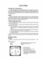
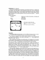
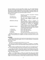
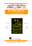
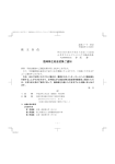
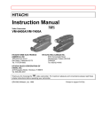
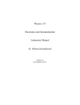
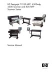
PA-1
SERVICE
MANUAL
PROFESSIONAL ARCADE
FUN & BRAINS
TABLE OF CONTENTS
Features .......................................... 3
Connection to TV .................................... 7
Hand Controls ...................................... 9
System Operation .................................. 11
Disassembly ...................................... 15
Glossary of Computer Terms .......................... 17
Mother Board Parts List .............................. 19
Final Cabinet Parts List .............................. 22
Layout and Schematic ............................... 23
2
FEATURES
AUTOMATIC TV PROTECTION
The Bally Professional Arcade is designed with a TV protection circuit. If the
unit is left unattended for approximately five minutes, the Bally Professional Arcade will automatically blank the screen and thus prevent any damage to a television receiver. To regain operation, all that is needed is to press any key on the
calculator keypad.
PAUSE
The Bally Professional Arcade includes a pause feature. To operate the pause
feature during the play of a game simply press the clear [C] key. Upon return,
press clear [C] again to resume, the game will appear on the screen at the exact
point at which it was when the pause was initiated.
REMOTE GAME SELECTION
All of the keypad entries required to select and initiate a game may be made
using the #1 hand control.
Turn the power switch on and a listing of the games (menu) by number should
appear on the TV screen.
1. Press the trigger. This signals the Arcade that you wish to use remote
game selection. A red number will appear in the lower-left corner of the TV
screen.
2. Twist the knob on the hand control to change the red number. Adjust the
knob until the number of entry that you want is shown.
3. Press the trigger again. This time it will register your choice with the Bally
Professional Arcade.
When a game is over, you can start another game by pulling the trigger to get
the menu. Then pull trigger, adjust knob, and pull trigger again to enter your
choice.
RESIDENT GAMES
Gunfight
Gunfight is a two-player game and uses the hand controls numbered "1" and
1'2" .
HAN D CONTROLS
Joy Stick ................ Walks the gun fighter around the screen.
Knob ................... Raises and lowers his arm.
Trigger ................. Shoots
I
CD
-
~
..,
•
1-.
i
..,
~
CD
CD
1. Each player's score.
2. The shots remaining.
3. Ten second timer starts after either
player runs out of ammo .
4. Each "scoring set" will have different
objects appear on screen between the
gunfighters. Your gunfighter will be able
to hide behind cacti, trees and even a
covered wagon.
3
Checkmate (0 to 4 players)
Scoring is accomplished as indicated in the following example. In a game with
four players, the first player to be eliminated scores zero, and the remaining
three score one point each. The next player eliminated also scores zero, and the
remaining two players each score another point. After all other players have
been eliminated, the remaining player will have scored three points ... and the
game is over.
HAN D CONTROLS
Joy Stick ................ Moves your symbol horizontally, vertically and
diagonally.
Knob ................... No function
Trigger ................. No function
1. Each player's symbol and score.
2. Each player's symbol on the playing
field.
3. The number of games remaining.
erB
Calculator
The programmable microprocessor unit in the Bally Arcade contains a 5- function, 1a-memory printing keypad calculator that scrolls on the TV screen.
The convenient algebraic entry system allows problems to be entered in the
same order they are written. If you want to calculate 3 + 4 - 5 you need only to
press [3][ + ][4][ - ][5][ =].
After choosing the calculator by pressing [3] on the keypad, the TV screen
should show a white background and a long orange horizontal bar near the bottom of the TV screen. This represents the viewing window of the calculator.
The calculator is easy to operate and can add, subtract, multiply, and divide. Using these four basic functions, we'll see exactly what takes place and how it
looks on your TV screen. Let us perform the operation 6 + 5 - 4 x 3 -;- 7 = ?, by
pressing, in order, the number and functions keys [6] [ + ] [5] [ - ] [4] [x] [3] [ -;- ] [7]
[=]. Looking at your TV screen, you'll see the answer-the sum total of your
calculation, aopears as "3 = .. in the orange window.
The calculations appearing directly above this window are the beginning of a
printed video tape revealing each entry and function performed. This unique
feature of the calculator will continue to record and store your calculations up to
a limit of 100 lines, allowing for lengthy and complex calculations. In addition, you
may recall to the TV screen, any previous calculation by simply pressing and
holding the scroll backward key [ ~ ] until your calculations appears! At this point,
it would be best to use the scroll forward key [ t ], and return to the end of the
video tape prior to any further calculations. Should you start new calculations
while in the middle of the video tape, they will be added in their proper location at
4
the end. Therefore, you will not see them as before. Your only visible indication
will be the line entries as they appear in the orange window. To clarify, the video
tape must be scrolled forward until the end of tape is reached. Should your
calculations exceed the 100 line limit, data at beginning of video tape will be omitted as new date is added, thus maintaining a tape of 100 lines.
Calculator Functions
(C) Clear Key
(CE) Clear Entry
(CH) Change Sign
(MS) Memory Storage
(MR) Memory Recall
( t ) Scroll Up
( ~ ) Scroll Down
(.) Decimal
(%) Percent
Removes all previous calculations including
memory storage.
Removes only the last entry from display.
The "CH" key changes the sign of the
displayed number. Negative numbers will appear in red.
Adds displayed number to memory, 10
individual entries to memory storage can be
made. Each time the MS key is used it should
be followed by pressing the appropriate
number key (1, 2, 3, etc.), to establish
numerical sequence within storage register.
Recalls number in memory to display. Must be
followed by appropriate number key to secure
correct memory from storage.
Moves video tape forward.
Moves video tape backward.
Enters a decimal point.
Calculates a percentage of the previous entry.
Calculator will display up to 10 digits to the left of the decimal point on your
screen. It will also store up to 10 digits to the right of the decimal, which are not
shown.
Scribbling
Scribbling is a fascinating creative game. By manipulating the various controls
you can create a multi-color pattern on the TV screen and draw or write almost
anything you choose.
How to Start
Press [4] on the keypad to get Scribbling on the screen.
Now that you've chosen Scribbling, the questions" # of players" will appear.
You can choose from zero to four by pressing the appropriate number key on the
keypad.
Before starting to scribble, place the plastic overlay for the keypad into position. This overlay outlines the functions controlled by the keys during Scribbling.
If you select zero players, the Arcade console will automatically trace an ever
changing pattern on your TV screen and continues until you press the reset key
or the clear key. (The automatic television protective circuit will not function
while in zero player mode.)
When 1 to 4 player action is chosen you should see one to four colored
squares on your screen. Movement of these squares is accomplished by movement of the Joy Stick in any of its eight directions. Squeezing and releasing the
trigger of the control will place a colored square anywhere you desire. If you wish
5
to draw a line, squeeze the trigger and hold. Move the Joy Stick in the direction
you wish to draw.
Rotate the top control knob to change the size and color of your square. In the
counter clockwise position of this knob you will see a large blue square. As you
begin to rotate in a clockwise direction the color will change to red, then green
and finally white. Continue to rotate and the size of the square will decrease and
again you will pass through the four basic colors.
One complete rotation from left to right produces 4 square sizes-large to
small-and the 4 basic colors which in effect puts a 16 position switch at your
fingertips.
Alternately squeezing and releasing the trigger while in motion produces a dotted line. To change from green in the display to orange, press the clockwise rotation key in the third row (Green) and hold, until green becomes orange and
release. The color clockwise and counter clockwise keys appear in the first two
rows (top to bottom) on the keypad, the next two rows of keys control the intensity
level of a color. When changing to any color or intensity of color, the key must be
held down until you reach the desired result.
Videocades
The Bally Arcade not only has four games built in, it has virtually hundred of
game possibilities! With optional Videocade™ cassettes, one can have a
veritable library of games and educational tools. Videocade™ cassettes are now
available in a variety of programs that include an Educational Series, a Sports
Series, an Action/Skill Series and a Strategy Series. And more are on the way!
6
CONNECTION TO TV RECEIVER
Included with the Bally Arcade is a TV adapter switch. This switch allows
selection of either the Bally Arcade or regular TV viewing. Simply move the slide
switch to the mode desired. "Game" position for Bally Arcade or "TV" position
for television.
I.
Adapter Switch Connections
A. Connection to sets having 300 ohm antenna system with screw
terminals. See figure 2.
1. Locate the VHF antenna terminal on the back of your television set.
Remove the existing wires connected to the VHF terminals. Attach
these wires to the terminals marked "Connect to Antenna" at the
base of the adapter switch.
2. Connect the short length of antenna wires coming from the side of
the adapter switch to the VHF terminals of your TV set.
B. Connection to sets having 75 ohm antenna system employing Round
Coaxial Cable and Cylindrical Connector. See figure 3.
Note: In this installation it will be necessary for you to purchase 75 ohm to 300 ohm
transformer, available from you local dealer or any television service organization.
1. Remove Coaxial Cable Connector from its socket on the back of the
TV set, then connect it to the socket of the transformer. Avoid bending of center wire in cable.
2. Connect the 300 ohm flat twin-lead wire coming from the end of the
transformer to the terminals marked "Connect to Antenna" on the
adapter switch.
3. Connect the short length of 300 ohm antenna wire coming from the
side of the adapter switch to the VHF terminals of your TV. (Additional TV adapter switches may be purchased at your local dealer so
you may install one on each television set in your home.)
CONNECT
TO ANTENNA
TV ADAPTER
SWITCH
CONNECTION TO
YOUR TV RECEIVER
o
VHF ANTENNA
WIRE
FIGURE 2
FIGURE 3
75.QHM COAXIAL CABLE INPUT
3OO-OHM TWIN LEAD INPUT
II.
III.
7&-OHM TERMINAL
(UNUSED)
Carefully unroll the Coaxial Cable from the Arcade console and plug it into
the TV adapter switch receptacle marked "Game".
Plug the power supply cord into a 120 volt AC outlet.
7
IV.
Plug each hand control unit into its appropriate plug on rear of console. See
figure 4.
V.
Move console On/Off switch (on back of console) to "On" position. See
figure 4.
IV.
Move slide switch on TV adapter to "Game" position.
VII. Turn on TV set and set Channel Selector to Channel 3 position.
The menu should now appear on the TV screen. (If not, press the reset
button.)
You now have a choice of Gunfight, or Checkmate Arcade Games, a 5function, 10-memory printing calculator or Scribbling, an exciting art form game.
Press the appropriate numbered button on the keypad to start the game of your
choice.
If the menu doesn't appear, check on the following:
Is the On/Off switch on the back of the console in the "On" position?
Is the switch on the TV adapter in the "Game" position?
Is the coaxial cable securely inserted into the adapter switch?
Is the power supply cord securely inserted into a 120 volt outlet?
Is the flat twin-lead wire properly hooked up to the back of the TV set?
Is your Channel Selector set on Channel 3?
The Bally Arcade is factory set to operate on Channel 3. If there is
interference from a Channel 3 TV station in your area, you can change to
Channel 4 by moving the slide switch of the RF modulator to position 4 and
setting your channel selector to Channe14.This switch is located on the left side
of your console. See figure5.
8
HAND CONTROLS
Each hand control is numbered on the top of its knob. It is important to insert
each control into its corresponding numbered location on the back of your Arcade (See figure 4).
The detailed action controlled by the hand controllers varies nth the game being played. Each pistol grip hand control has several functions which determine
the action seen on the screen.
Squeezing the trigger activates a switch for shooing as in Gunfight or placing
a trace on the screen as in Scribbling.
The knob on top of the control can be moved in 8 directions, forward,
backward, left, right, and at 45 degree angles.
These motions determine the movement of the image on your scre6n.
Rotating this knob positions the cowboys hand during Gunfight, etc. Review
hand control actions for each individual game. Notice that the knob moves
easily. Under no circumstances should the knob be forced.
Figure 6
Hand Held
Figure 7
Top View
9
GENERAL SPECIFICATIONS
M icroprocessor- Z-80
Memory
RAM (Scratchpad)
ROM (Resident)
ROM (Cassette)
-
Inputs
Calculator Keypad
Dial
Joystick
Light Pen-Bar Code Reader
Output Graphics
Resolution
Configuration
Display
Number of Colors
-
4K Bytes
8K Bytes
8K Bytes (Max.)
-
24 Keys
-4
-4
-
Provision
16,320
160 x 102
Color-Black and White
256
Output Audio -
1 Channel Triple Tone Tremelo and Vibrato
Output Signal -
NTSC Standard Color
Output Channels -
3 and 4
Calculator
Keypad
Function
Memory
-24 Keys
- Add, Subtract, Multiply, Divide and Percent
- 10 Separate
Power Requirements
Power Consumption
- Standard 120 VAC
-12 WAITS (Ave.)
Additional Specifications with Bally Basic "Videocade"
Language
Baud (with Interface)
-
Output Text
Text Display
Text Capacity
-286
- 26 x 11
Basic
300BPS
10
SYSTEM OPERATIO'N
GENERAL
The Bally Professional Arcade is a full color video game system based on the
mass-ram-buffer technique. A mass-ram-buffer system is one in which one or
more bits of RAM are used to define a color and intensity of a pixel (dot) on the
screen. The picture on the screen is defined by the contents of RAM and can
easily be changed by modifying RAM.
The system uses a Z-80 Microprocessor as its main control unit. The system
contains 4K Byte RAM and 8K Byte ROM. The resident ROM has software for four
games: Gunfight, Checkmate, Scribbling, and a five function 10 memory
Calculator. Additional ROM in cassette form can be accessed through the
cassette connector. Three custom chips are used for the video interface, special
video processing functions, audio generation and keyboard and control handle
interface.
The system will accommodate up to four player control handles at once. Each
handle has five switches and a potentiometer. These switches are read by the
Z-80 via the 1/0 chip. The signals from the potentiometers are changed to digital
information by an 9 bit Analog to Digital Convertor within the 1/0 chip.
Provisions for expansion are provided for a full keyboard via an IEEE Bus along
with a separate input to accommodate a light pen.
OPERATION
When the Bally Arcade is turned on, the Z-80 microprocessor begins executing
instructions out of ROM. This ROM can also be from a cassette that is plugged into the cassette connector. The first thing the Z-80 does is write data into the RAM
so that the menu appears on the screen. What is seen on the screen is a continuous dump of the data in the RAM at that instant. The data in RAM is not exactly the same data that the Z-80 pulled from ROM. The data is modified along the
way by the Z-80 dependant upon the state of the switches, knobs, or triggers.
Depending on the state of these the Z-80 makes decisions and modifies the data
accordingly on the way to the RAM.
MICROPROCESSOR (CPU)
The task of the microprocessor is to receive data in the form of binary digits
(1 's and O's), to store the data for later processing, to perform arithmetic and
logic operations on the data in accordance with previously stored instructions
and to deliver the results to the user through an output mechanism. A block
diagram of a typical microprocessor would show the following units: A decode
and control unit (to interpret instructions from the stored program), the
Arithmetic and logic unit or ALU (to perform arithmetic and logic operations),
registers (to serve as easily accessible memory for data frequently manipulated),
an accumulator (a special register closely associated with the ALU), address buffers (to supply the control memory with the address from which to fetch the next
instruction), and input-output buffers (to read instructions or data into the
microprocessor or to send them out).
MICROCYCLER
The task of the microcycler is to combine the 16 bit Address Bus and the 8 bit
Data Bus from the Z-80 into one 16 bit Microcycle Data Bus to the Data Chip, Address Chip and 1/0 chip. This was done to reduce the pin count on the custom
chips.
11
ADDRESS CHIP
The address chip has several tasks.
1. It provides an interface for the light pen.
2. It multiplexes the 16 bit Microcycle Data Bus from the Z-80 into a 6 bit
bus for the RAM. This is necessary because the RAM's only have 6 pins
available for information processing.
3. It synchronizes with the data chip to insure that the data being dumped
from RAM, for display on the screen, is displayed at the proper time.
4. Because of the slow speed of the microcycler and of the address chip
the address chip generates a wait signal to the Z-80 telling it to wait until
the instruction being processed is completed before the next instruction
is started.
DATA CHIP
One of the data chips most important functions is to generate the correct clock
frequency used by the rest of the system. The data chip receives a 7 MHZ frequency from the clock driver circuitry, and this frequency is divided down by
counters to generate a frequency of 1.7 MHZ, which is used throughout the
system. The 1.7 MHZ is shown on the schematic as O.
The data chip also generates Pixclock (PXCLK) which is 3.547 MHZ.
This is used to synchronize the RAM's with the data chip to insure the proper
timing and colors when data is being dumped from the RAM's for display on the
screen.
The data chip also generated R-Y, B-Y and the composite video which is output
to the RF modulator.
1/0 CHIP
The Z-80 communicates with the 110 chip through input and output instructions. The state of an 8 x 8 switch matrix can be read through the Switch Scan circuit. When an input instruction is executed, one of the SOO-S07 lines will be activated. When a line is activated, the switch matrix will feed back 8 bits of data on
S10-S17. This data is in turn fed to the Z-80 through MUXDO-MUXD7.
The Z-80 can read the position of the four hand control potentiometers through
the Analog-Digital Convertor Circuit. These pots are continuously scanned by the
A-D Convertor and the results of the conversions are stored in a RAM in the A-D
Convertor Circuit. The Z-80 simply reads this RAM with input instructions.
Also included in the 110 chip are the audio registers.
The Z-80 loads data into the Music Processor with output instructions. This
data determines the characteristics of the audio that is generated.
MUSIC PROCESSOR
The music processor can be divided into two sections. The first section
generates the Master Oscillator Frequency and the second section uses the
Master Oscillator Frequency to generate tone frequencies and the analog audio
output. The contents of all registers in the Music Processor are set by output instructions from the Z-80.
Master Oscillator Frequency is a square wave whose frequency is determined
by the 8 binary inputs to the Master Oscillator. This 8-bit word is the sum of the
12
contents of the Master Oscillator Register and the output of the MUX. The MUX is
controlled by MUX REG.
If MUX REG contains 0, then data from the Vibrato System will be fed through
the MUX. The two bits from the Vibrato Frequency Register determine the frequency of the square wave output of the Low Frequency Oscillator. The 6-bit
word at the output of the AND gates oscillates between 0 and the contents of the
Vibrato Register. The frequency of oscillation is determined by the contents of
the Vibrato Frequency Register. The 6-bit word, along with two ground bits are
fed through the MUX to the Adder. This causes the Master Oscillator Frequency
to be modulated between two values thus giving a vibrato effect.
If MUX REG contains 1, then data from the Noise System will be fed through
the MUX. The 8-bit word from the Noise Volume Register determines which bits
from the Noise Generator will be present at the output of the AND gates.
13
SYSTEM BLOCK DIAGRAM
~
Z-80
CPU
ADDRESS
CHIP
MICROCYCL!""'
U7
US-UIO
8K BYTE
SYSTEM I---ROM
UI-U4
8K BYTE
CASSETTE
~>ROM
4 K BYTE
RAM
r--
UI7
I----
DATA
CHIP
r-
I/O
CHIP
'----
U24-U31
RF
CH. 30R4 TO
MODULATOR ~ T. V. RECEIVER
r--
UI8
CONTROL
HANDLES
(1-4)
LIGHT PEN
r-
24 BUTTON
KEYmD
UI9
>--
IEEE EXPANDER
BUS
E:DCPA D
C.ONNECTOR
1
EY PAD
_---'1:nEiiiiiii
CI.JST
!)Al A
5U
y----.,i
E'~
14
NO.~
DISASSEMBLY PROCEDURE
FOR REPLACING GAME BOARD
1. Using a magnetized phillips screwdriver remove the five (5) screws on the
bottom of the cabinet (figure 1 item 1). Holding the top and bottom sections
together, turn the cabinet right-side up.
2. Lift up gently on the top section and it will separate from the bottom section.
3. On the left side of the unit you will see the R. F. Modulator, (figure 2 item 1)
and the four (4) wire power connector (figure 2 item 2). Remove the R. F.
Modulator by lifting up on the left side of it and pulling outwards to the left.
The power connector can be removed by pulling it towards the rear of the
unit.
4.
Using a magnetized phillips screwdriver remove the four (4) screws in the
corners of the board (figure 2 item 3). At this time the game board and
keypad/cassette assembly can be removed from the bottom of the cabinet.
5. Remove the silver clips that are attached to the edges of the shielding
(figure 2 item 4). After the clips are removed the metal shielding on the bottom of the game board can be removed.
6. Turn the board over and remove the four (4) remaining phillip screws that
secure the keypad/cassette assembly to the game board (figure 3 item 1).
7.
Holding the two pieces together turn them over and carefully lift the
keypad/cassette assembly away from the game board.
8. Holding the keypad/cassette assembly in your right hand, press down gently
on the keyboard itself with your left hand and slide the keyboard completely
out.
9. Remove the reset button and the remaining plastic shielding by pulling them
up and off gently.
10. Reverse the above steps to install a new game board.
IMPORTANT NOTE: Insure that all shielding is in place and secure to conform to FCC regulations.
15
Fog. 2--i11<IT Win! TOP REloIOVED
1_''-'. '
.
•__ 0".
____ 1.. _ _ .. _
. ""_
Fog 3 BDTTDMDI'GAME II()I.RO
16
.. _
GLOSSARY OF COMPUTER TERMS
Accumulator: a register in the microprocessor that operates on data. It is socalled because these registers were first used to accumulate totals.
Address: a specific memory location that is called out by the program counter.
ALU (arithmetic and logic unit): the circuitry that performs the manipulations on
data held in the accumulator.
Assembly Language: a compromise between the user's thoughts and the
numerical notation of the microprocessor. Assembly language is the closest
technique to the actual numerical codes that still retains some speakinglanguage characteristics.
Bit: a minimum logic element. A binary number of either 0 or 1.
Branch: depending on the status of a particular bit in the status register, the program will jump by the indicated amount if the condition is met, or merely increment if not.
Bus: a group of wires that carry related binary signals, usually a word, as in a
16-wire address bus. A bus can be bidirectional, as in the case of a data bus.
Byte: a word consisting of eight bits.
Cross-Assembler: a program on a larger computer that allows a
microprocessor programmer to use assembly language. The assembler reduces
the program to the machine language.
Decoder: usually a device that detects a certain specific address on the address bus.
DMA (direct memory access): a process in which a microprocessor is removed
temporarily from a system to allow data to be transferred rapidly in or out of
memory without microprocessor control.
EPROM: A PROM that can be erased and reused indefinitely. Most EPROM's
are erased under ultraviolet light and can be recognized by the clear cover over
the silicon "chip."
Hex: short for hexadecimal: numbers calculated to the base 16.
Interrupt: an external signal that causes a microprocessor to jump to a specific
subroutine. Interrupts are maskable or nonmaskable. A maskable interrupt may
be delayed until a mask bit is lowered.
1/0 (input/output): hardware that interfaces a microprocessor system with the
outside world.
Iterative Loop: a programming technique whereby a process is repeated a
specified number of times.
Jump: a programming instruction that breaks the consecutive-instruction programming sequence and resumes elsewhere in the program.
Machine Language: Numerical coding, representing instructions, usually in
the form of groups of bytes, used by the microprocessor.
Peripheral: a unit operated with a microprocessor system such as a keyboard
or a printer.
17
Port: a place through which inputs and outputs-either data or instructionsare channeled. A microprocessor can have more than one port of can address
many. Port size, though, is often specified in bits, ranging from 4 to 16 bits.
Processor Status Word (PSW): a word of readily available status information
provided to indicate the result of specific operations.
Program: a set of sequential instructions that a computer follows.
Program Counter: two 8-bit registers used to generate the 16-bit address. The
registers are called PCH and PCl and are used for the higher-order and lowerorder bytes, respectively.
PROM: a programmable ROM in which a program is entered by the user before
installation into equipment, as opposed to a factory-programmed ROM.
RAM (random-access memory): a data-storage device that can retain and produce on demand any data placed in it.
Register: a device that stores one word of data, and often consists of several
flip-flops.
ROM (read-only memory): a device that has data permanently entered into if to
be outputted on demand.
R/W (read/write): a control output of the microprocessor that indicates if data
are being transferred from the microprocessor to memory, or vice versa.
Scratchpad: an area of the main memory set aside for short and often done
calculations.
Stack: storage for data during subroutines or interrupts.
Stack Pointer: two 8-byte registers containing the address of the top (most recent end) of the stack.
Subroutine: a program within a program that performs a specific, often-used
function.
Vector: a specific address loaded into a microprocessor's program counter to
force the microprocessor to start processing at a specific address.
18
MOTHER BOARD PARTS LIST
Component #
Bally Part Number
Description
INTEGRATED CIRCUITS
U1
U2
U3
U4
US
U6
U7
U8
U9
U10
U11
U12
U13
U14
U1S
U16
U17
U18
U19
U20
U21
U22
U23
U24-U31
U32
ROM 93168 HVSD
ROM 931 68 HVSC
ROM 93168 HVS8
ROM 93168 HVSA
74LS367
74LS04
Z-80 CPU
74LS2S7
74LS2S7
DP8304
74LS02
74LSOO
74LS10
74LS10
74LS02
74LS74
Custom Address
Custom Data
Custom I/O
74LS174
74LS74
74LS74
DM81 LS9S
M K4096N-1S RAM
7S361AP
0066-8S1 AX-HVSD
0066-8S1 AX-HVSC
0066-8S1 AX-HVS8
0066-8S1 AX-HVSA
0066-700AX-XXCX
0066-473XX-XXCX
0066-1248X-XXWX
0066-643AX-XXCX
0066-643AX-XXCX
0066-968AX-XXAX
0066-463XX-XXCX
0066-4S3XX-XXCX
0066-S02XX-XXCX
0066-S02XX-XXCX
0066-463XX-XXCX
0066-823XX-XXCX
0066-11SXX-XXYX
0066-116XX-XXYX
0066-11 7XX-XXYX
0066-243AX-XXCX
0066-823XX-XXCX
0066-823XX-XXCX
0066-967 AX-XXAX
0066-308XX-XXWX
0066-7S4AX-XXCX
CAPACITORS
C1
C2-CS
C6
C7
C8
C9
C10
C11-C12
C13
C14
C1S
C16
C17
C18
C19
C20-C47
1S00MF 2SV
.1 M FDSOV ZSU
10,000MF 10V
1S MFD 20V
6.8MFD 3SV
.1 MFD SOV ZSU
100MFD 16V
.1 MFD SOV ZSU
1 MFD 3SV
.1 MFD SOV ZSU
100PF SOV
27PF SOV S%
22PF SOV
33PF SOV S%
.039MF SOV
470PF SOV
0061-297EX-SE8X
0061-132H81JSC
0061-322CX-SE8X
0061-207D4-4ERX
0061-193G6-4E RX
0061-132H8-1 JSC
0061-233DX-SE2X
0061-132H8-4ERX
0061-163G6-4ERX
0061-132H8-4ERX
0061-043H6-1 JSX
0061-028H2-1 JSX
0061-02SH6-1 JSX
0061-020H2-1 JSX
0061-117H2-1JSX
0061-061 H6-1 JSX
19
Component #
Description
Bally Part Number
C48
C49-C50
C51
C52-C55
C56-C61
C62-C64
C65-C106
.1 MFO 50V Z5U
33PF 50V 20%
.1 MFO 50V Z5U
22PF 50V
100PF 50V
15MFO 20V
.1 MFO 50V Z5U
0061-132H8-1 J5C
0061-030H6-1 J5X
0061-132H8-1 J5C
0061-025H6-1 J5X
0061-043H6-1 J5X
0061-20704-4ERX
0061-132H8-1 J5C
RESISTORS
R1
R2
R3
R4-R5
R6
R7
R8
R9
Rl0
Rl1
R12-R13
R14
R15
R16-R17
R18
R19-R21
R22-R25
R26-R31
R32
R33
R34
R35-R36
R37-R38
R39
R40-R42
270hm 1w 5%
2400hm Xw 5%
1500hm Y:;w 5%
2KohmXw5%
1M ohm Xw 5%
10k ohm Xw 5%
2.2k ohm Xw 5%
22k ohm Xw 5%
11kohmXw5%
330 ohm Xw 5%
82 ohm Xw 5%
62 ohm Xw 5%
47 ohm Xw 5%
1k ohm Xw 5%
150 ohm Xw 5%
2k ohm Xw 5%
6.2k ohm Xw 5%
8.2k ohm Xw 5%
1k ohm Xw 5%
3.3k ohm Xw 5%
8.2k ohm Xw 5%
3.3k ohm Xw 5%
47 ohm Xw 5%
10k ohm Xw 5%
2K ohm Xw 5%
0062-068F3-1 XXX
0062-13583-1 XXX
0062-12203-1 XXX
0062-19383-1 XXX
0062-32383-1 XXX
0062-22783-1 XXX
0062-19583-1 XXX
0062-24383-1 XXX
0062-22983-1 XXX
0062-14483-1 XXX
0062-1 0483-1 XXX
0062-09583-1 XXX
0062-08683-1 XXX
0062-1 7983-1 XXX
0062-12283-1 XXX
0062-19383-1 XXX
0062-21783-1 XXX
0062-22383-1 XXX
0062-17983-1 XXX
0062-20383-1 XXX
0062-22383-1 XXX
0062-20383-1 XXX
0062-08683-1 XXX
0062-22783-1 XXX
0062-1 9383-1 XXX
TRANSISTORS
01
02
TIP 31
TIS 137
0065-485XX-XXMX
0065-500XX-XXMX
CRYSTAL
Y1
14.31818MHZ XTAL
20
0069-079XX-XX2X
Component #
Description
Bally Part Number
DIODES
CR1-CR8
CR9-CR28
0064-030XX-XXPG
0064-048XX-XXPX
IN4004
IN4148
VOLTAGE REGULATORS
VR1
VR2
VR3
VR4
LM342-P-15
LM342 P-10
UA78GUIC
LM320 MP
0066-024BX-XXAX
0066-025BX-XXAX
0066-250BX-XXBX
0066-026BX-XXAX
SWITCHES
S1
S2
on, off switch
Reset switch
0017-00032-0049
0017-00032-0048
JACKS
J1
J2-J5
J6
J7
R.F. Modulator Conn.
Player Handle Conn.
Cassette Conn. 26 Pin
Lite Pen Conn.
3000-16337-0000
0017-00021-0291
0017-00021-0273
3000-16336-0000
MISCELLANEOUS
Oscillator Fence
Thermalloy Heat Sink
Thermalloy Heat Sink (2)
Keyboard 24 Button
6-32X %screw for
cassette conn.
6-32 nuts for above
Line Filter Assy.
Power Supply Conn. 4 pin
21
0620-00114-0000
0068-031 XX-XXAX
0068-032XX-XXAX
0017-00003-0191
0017 -00101-0774
0017-00103-0060
A620-00034-0000
3000-16326-0400
..
I
FINAL CABINET PARTS LIST
Description
R. F. modulator
U Clip 8/unit
%0 x %4/unit
%0 x 1 4/unit
%2 x %5/unit
Nylon Spacer 4/unit
Consol Packaging Mat
Keyboard Overlay
Ejector Spring
Owner's Manual
Knob #2
Knob #3
Knob #4
R. F. Coax Cable
R. F. Adaptor
Cabinet Top
Cabinet Base
Top Cover Tape Lid
Keyboard Housing
Ejector Button
. Ejector
Reset Button
Name Plate
R. F. Shield Top
Control Handle
Power Supply Assembly
Mother Board
Bally Part Number
0017-00003-0190
0017-00007-0135
0017-00101-0067
0017-00101-0074
0017-00101-0776
0017-00042-0170
0620-00011-0000
0620-00111-0000
0620-00247-0000
0620-00302-0000
0620-00907 -0200
0620-00907-0300
0620-00907-0400
0620-00910-0000
0620-00912-0000
0620-00913-0000
0620-00914-0000
0620-00915-0000
0620-00916-0000
0620-00919-0000
0620-00920-0000
0620-00921-0000
0620-00923-0000
0620-00939-0000
A620-00003-0100
A620-00004-0000
A620-00933-0800
22
NOTES
23
51
Jc
J4
J3
J.5
$
®
®© ~
u
?
U It)
115
?
®
I
~® ~®
-m!l-
®®~
®~ u,
I
®~
I
II /I
o
R F
/v1::}LJUL4TOR
"\.)
o
\9
o
\.)
i--
I
i-
I
EB
$
uzz
I>
at,
CIA
IJ
C$4
HANDl..6/
"AI IJ~)
Bally Service Manual
Version 1.0 - Released Nov 10, 2000
This document has been scanned and converted to PDF format courtesy of the Bally Alley newsletter. For other reprints and more information visit:
http://www.ballyalley.com
Corrections? Suggestions? Email Adam Trionfo at: [email protected]
MANUFACTURED BY
BALLY MANUFACTURING • CORPORATION CONSUMER PRODUCTS DIVISION
10750 W. GRAND AVE. • FRANKLIN., IL 60131
CABLE ADDRESS MIDCO • TELEX NO. 72-1596
678
Printed in U.S.A.
620-303