1
MicroVAX 3100
Model 85/95
Troubleshooting and Diagnostic
Information
Order Number: EK-A0719-TM. 801
June 1994
This manual describes the troubleshooting procedures and diagnostic
commands that you can use to solve basic problems with the
MicroVAX 3100 Model 85 and Model 95 systems.
Revision Information:
Digital Equipment Corporation
Maynard, Massachusetts
This manual supersedes EK-A0719-TM. AOI
June 1994
Digital Equipment Corporation makes no representations that the use of its products in the
manner described in this publication will not infringe on existing or future patent. rights, nor do
the descriptions contained in this publication imply the granting of licenses to make, use, or sell
equipment or software in accordance with the description.
Possession, use, or copying of the software described in this publication is authorized only pursuant
to a valid written license from Digital or an authorized sublicensor.
FCC NOTICE: This equipment has been tested and· found to comply with the limits for a Class
A digital device, pursuant to Part 15 of the FCC Rules. These limits are designed to provide
reasonable protection against harmful interference when the equipment is operated in a commercial
environment. This equipment generates, uses, and can radiate radio frequency energy and, if not
installed and used in accordance with the instruction manual, may cause harmful interference to
radio communications.
Any changes or modifications made to this equipment may void the user's authority to operate this
equipment.
Operation of this equipment in a residential area may cause interference in which case the user
at his own expense will be required to take whatever measures may be required to correct the
interference.
© Digital Equipment Corporation 1994. All Rights Reserved.
The postpaid Reader's Comments form at the end of this document requests your critical evaluation
to assist in preparing future documentation.
The following are trademarks of Digital Equipment Corporation: Digital, MicroVAX, OpenVM8, RX,
ThinWire, VAX, VAX DOCUMENT, and the DIGITAL logo.
All other trademarks and registered trademarks are the property of their respective holders.
82613
This document was prepared using VAX DOCUMENT Version 2.1.
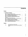
Contents
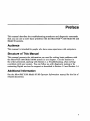
Preface. . . . . .. . . . . . . . .. . . . .... ... . . ... ... .......... ... .
v
1 Troubleshooting and Diagnosing Problems
1.1
1.2
1.3
1.3.1
1.3.2
1.3.3
1.3.4
1.3.5
1.4
1-1
'l'roubleshooting . . . . . . . . . . . . . . . . . . . . . . . . . . . . . . ..
U sing the 'l'roubleshooting Table ...................
Diagnostic Tests and Commands ...................
Power-Up Tests .............................
Diagnostic Tests and Utilities ..................
Power-Up Error Messages .....................
Configuration Display ........................
Error Display ...............................
Contacting Digital Services .......................
.
.
.
.
.
.
.
.
.
1-2
1-9
1-10
1-13
1-18
1-22
1-24
1-25
SYNC Test Failure ...........................
Memory_Setup_CSRs Test Failure ...............
Memory_Count_Pages Test Failure ..............
No_Memory_Present Test Failure ...............
.
.
.
.
1-18
1-19
1-20
1-21
Index
Examples
1-1
1-2
1-3
1-4
iii
Figures
1-1
1-2
Diagnostic Tests . . . . . . . . . . . . . . . . . . . . . . . . . . . . . .
Status LED Display .......................... .
1-13
Basic Troubleshooting ........................ .
Option Card Tests ........................... .
MicroVAX 4000-100A/I05A Tests ................ .
1-3
1-15
1-26
Tables
1-1
1-2
1-3
iv
1-16
Preface
This manual describes the troubleshooting procedures and diagnostic commands
that you can use to solve basic problems with the MicroVAXTM 3100 Model 85 and
Model 95 systems.
Audience
This manual is intended for people who have some experience with computers.
Structure of This Manual
This manual presents the information you need for solving basic problems with
the MicroVAX 3100 Model 85/95 system in one chapter. Use the sections in
the order presented, starting with Section 1.1, Troubleshooting, when solving
a problem with your system. You can follow up with diagnostic testing or by
contacting Digital services for support as described in Section 1.3 and Section 1.4.
Additional Information
See the MicroVAX 3100 Model 85195 Operator Information manual for the list of
related documents.
v
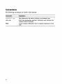
Conventions
The following conventions are used in this manual:
Convention
Description
MONOSPACE type
'!ext displayed on the screen is shown in monospace type.
Italic type emphasizes important information and indicates the
complete titles of manuals.
italic type
Note
Warning
vi
A note contains information that is of special importance to the
user.
A warning contains information to prevent personal injury.
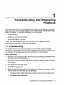
1
Troubleshooting and Diagnosing
Problems
This chapter describes the troubleshooting procedures and diagnostic commands
that you can use to solve basic problems with the MicroVAX 3100 Model 85 and
Model 95 systems. It contains information on the following:
•
Troubleshooting
•
Diagnostic tests and commands
•
Contacting DigitaPM services
It also lists the information that you must give to your Digital services
representative and where to find this information.
1.1 Troubleshooting
If a problem occurs, you must first make sure that all the cables, loopback
connectors, and terminators are correctly connected and that the connectors are
not damaged, for example, the pins may be broken or short-circuited.
Follow these steps:
1. Shut down the operating system by following the procedures described in the
operating system documentation.
2. Turn off the console terminal and all the peripheral devices, such as printers
and moderns.
3. Turn off all the expansion boxes.
4. Turn off the system unit.
5. Check that the following cables, if installed, are correctly connected at both
ends and that the connectors are not damaged:
•
Console terminal cable Oinking the console terminal to the system unit)
•
Console terminal power cord
Troubleshooting and Diagnosing Problems 1-1
•
System unit power cord
•
Expansion box SCSI cables
•
Expansion box power cords
•
Thin Wire ™ Ethernet cable or standard Ethernet cable
6. Check that the following terminators, if installed, are correctly connected and
are not damaged:
•
SCSI terminators
•
Thin Wire Ethernet terminator (T-connector and two terminators)
• Standard Ethernet loopback connector
If you have correctly followed steps 1 to 5, the on/off switches on all the
components are set to the off (0) position, and you have solved any problems
caused by incorrectly connected cables or terminators.
7. Set the on/off switches on the following equipment to the on ( I ) position in
the following order:
a. Expansion boxes
b. Peripherals
c.
Console terminal
d. System unit
The system responds with the power-up test display. If it does not, see
Section 1.2.
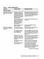
1.2 Using the Troubleshooting Table
Table 1-1 suggests the corrective actions for certain system problems. If you have
a problem with the system, follow these steps:
1. Write down the symptoms of the problem.
2. Check the Symptom column in Table 1-1 for a match.
3. Check the causes of the symptom in the Possible Cause column. If the
column lists more than one possible cause, check the possible causes and
their suggested solutions in the order listed.
4. Follow the advice in the Suggested Solution column.
5. See Section 1.4 if the problem persists.
1-2 Troubleshooting and Diagnosing Problems
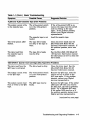
Table 1-1 Basic Troubleshooting
Symptom
Possible cause
Suggested Solution
The power cord is not
connected. The power
cord may be faulty. The
power socket may not
be working. The system
breaker or wall outlet
may have blown.
Make sure that all the power cords
are connected correctly at both
ends. Try a known good power cord
or test the power socket with an
appliance that works.
The overload protection
circuitry of the power
supply may have shut
down because of an
abnormal condition on
the power line.
Tum the system off' and then turn
it back on.
The power supply unit
(PSU) is faulty.
Contact your Digital services
representative.
The terminal cable is
not correctly connected.
Make sure that all the cables are
connected at both ends.
The terminal cable is
not connected to the
correct MMJ port.
Check the MMJ port to which the
terminal cable is connected. If this
port is not MMJ port 3, remove the
terminal cable and connect it to
MMJ port 3.
The power cord is not
connected. The power
cord may be faulty. The
wall outlet may not be
working.
Make sure. that all the power cords
are connected correctly at both
ends. Try a known good power cord
or test the power socket with an
appliance that works.
The terminal fuse may
have blown.
Replace the blown terminal fuse.
See the terminal documentation.
The terminal settings
may be incorrect.
See the MicroVAX 3100 Model
85/95 Operator Information
manual for the list of correct
terminal settings. See the terminal
documentation for information on
how to set up the terminal.
System Problems
The system unit fan is
off' or the power light is
off'.
The power-up display
does not show after 20
seconds.
.
(continued on next page)
Troubleshooting and Diagnosing Problems 1-3
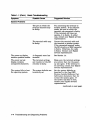
Table 1-1 (Cont.) Basic Troubleshooting
Symptom
Possible Cause
Suggested Solution
The port to which the
terminal connects may
be faulty.
Try connecting the terminal to
another system. If this solution
works, the port to which the
terminal was connected is faulty.
If the terminal still does not
operate, it is faulty. In either
case, contact your Digital services
representative.
The terminal cable may
Connect the terminal cable and
the terminal to another system.
If the connected terminal works,
the DZ circuitry or MMJ connector
is faulty. Otherwise, the cable
is faulty. Contact your Digital
services representative.
System Problems
be faulty.
The power-up display
contains question marks.
See Section 1.4.
The power-up test
display contains
unexpected characters.
A diagnostic error has
occurred.
The terminal settings
are incorrect or the DZ
circuitry is faulty.
The system fails to boot
the operating system.
The system defaults are
incorrectly set.
Set the system defaults as
described in the Open VMS
Factory Installed Software User
Information document, then try
to boot the system again. If
the system still fails to boot,
contact your Digital services
representative.
(continued on next page)
1-4 Troubleshooting and Diagnosing Problems
Make sure the terminal settings
are correct, then run the powerup test again. If the terminal is
set correctly, contact your Digital
services representative.
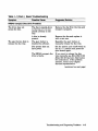
Table 1-1 (Cont.) Basic Troubleshooting
Symptom
Suggested Solution
Possible Cause
RRD43 Compact Disc Drive Problems
The drive does not
accept the disc.
The eject button fails to
release the disc tray.
The disc is upside-down
in the tray or it is not
placed correctly in the
tray.
Remove the disc from the tray and
reinsert it properly.
A disc is already
present.
Remove the disc and replace it
with a new one.
The eject button is
disabled by software.
Reenable the eject button or
manually release the disc tray.
The system does not
have power.
Set the system unit on/off switch to
the on ( I ) position and press the
eject button again.
The RRD43 compact disc
drive is faulty.
If you want to release the disc
tray manually, see MicroVAX 3100
Model 85/95 Operator Information
for instructions. If the problem
persists, contact your Digital
services representative.
(continued on next page)
Troubleshooting and Diagnosing Problems 1-5
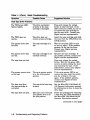
Table 1-1 (Cont.) Basic Troubleshooting
Symptom
Possible Cause
Suggested Solution
The TZ30 green LED
flashes rapidly.
The drive mechanism
is faulty or the tape
cartridge is damaged.
Press and release the unload
button to clear the fault. If the
LED continues to flash, do not try
to remove the tape cartridge or
use the tape drive. Contact your
Digital services representative.
The TZ30 does not
operate.
The drive does not
contain a tape cartridge.
Insert the tape cartridge and slide
the lever from the UNLOCK to the
LOCK position.
The operate lever does
not slide.
The tape cartridge is in
use.
Wait for the green LED to turn
on and try again. If the problem
persists, do not use the drive.
Contact your Digital services
representative.
The operate lever does
not lock.
The tape cartridge is not
inserted correctly.
Reinsert the tape cartridge. If
the problem persists, contact your
Digital services representative.
TZ30 Tape Drive Problems
Press and release the unload
button. Wait for the green LED
to turn on before sliding the lever
and removing the tape. If the
LED flashes, contact your Digital
services representative.
The tape does not load.
The system cannot write
to the tape.
The write-protect switch
is in the write-protect
position.
If the write-protect LED is on,
remove the tape, reset the switch
and try writing to the tape
again. If the problem persists,
contact your Digital services
representative.
The data read from
the tape cartridge is
corrupted.
The tape drive head may
be dirty.
See the MicroVAX 3100 Model 85
/95 Operator Information manual
for infonnation on how to clean the
drive head.
The tape does not eject.
The tape is not rewound.
The operate lever is in
the lock position.
Follow the procedure for removing
a tape from the TZ30 described in
the MicroVAX 3100 Model 85/95
Operator Information manual.
(continued on next page)
1-6 Troubleshooting and Diagnosing Problems
Table 1-1 (Cont.) Basic Troubleshooting
Symptom
Possible Cause
Suggested Solution
TLZ06 and TLZ07 Cassette Tape Drive Problems
The write-protect switch
is in the write-protect
position.
If the write-protect LED is on,
remove the tape, reset the switch
and try writing to the tape
again. If the problem persists,
contact your Digital services
representative.
The cassette tape is not
loaded.
Load the cassette tape.
The write-protect LED
flashes.
The tape drive heads
are dirty or the tape is
worn.
Clean the drive heads (see the
MicroVAX 3100 Model 85195
Operator Information manual). If
the problem persists, use a new
tape.
The data read from
the cassette tape is
corrupted.
The tape drive heads
may be dirty.
See the MicroVAX 3100 Model 85
195 Operator Information manual
for information on how to clean the
drive heads.
The system cannot write
to the cassette tape.
TZK10ITZK11 Quarter Inch Cartridge (QIC) Tape Drive Problems
The data read from the
QIC tape is corrupted.
The drive head is dirty.
Clean the drive head. See the
MicroVAX 3100 Model 85195
Operator Information manual.
The system cannot write
to the QIC tape.
The write-protect switch
is in the write-protect
position.
Remove the QIC tape, reset the
switch and try to write to the
QIC tape again. If the problem
persists, contact your Digital
services representative.
The system cannot read
from or write to the QI C
tape.
The QIC tape may be
faulty.
Remove the QIC tape. If the amber
LED turns off when you remove
the QIC tape, the tape is probably
faulty. Try a different QIC tape.
If the amber LED stays on or if
the problem persists, contact your
Digital services representative.
(continued on next page)
Troubleshooting and Diagnosing Problems 1-7
Table 1-1 (Cont.) Basic Troubleshooting
Symptom
Possible Cause
Suggested Solution
RX™26 Diskette Drive Problems
The system cannot read
from or write to the
diskette.
The diskette is not
formatted.
Format the diskette.
The diskette is not
correctly inserted.
Eject the diskette. Try to insert the
diskette again.
The diskette is faulty.
The diskette drive is
faulty.
Try a different diskette.
Contact your Digital services
representative.
The diskette density is
incorrect.
The RX26 accepts only highdensity (HD) or extra-density
(ED) diskettes.
The diskette drive head
may be dirty.
See the Micro VAX 3100 Model 85
/95 Operator Information manual
for information on how to clean the
diskette drive head.
The system can read
from but cannot write to
a diskette.
The write-protect switch
is in the write-protect
position.
Eject the diskette and reset the
switch. Try writing to the diskette
again.
The diskette does not
eject.
The diskette is
incorrectly positioned
in the drive.
Gently press the diskette with your
finger and reposition it. Press the
eject button again.
RZ-Series SCSI Disk Drive Problems
An installed drive does
not work.
Two SCSI identifiers are
set to the same number.
Drive cables are not
properly connected.
The Configuration
display does not show a
SCSI device.
Reset each SCSI ID to a unique
number.
Check the cable connections.
SCSI device is not
properly terminated.
Check for a SCSI 50-pin
terminator.
Two SCSI identifiers are
set to the same number.
Reset each SCSI ID to a unique
number.
1-8 Troubleshooting and Diagnosing Problems
1.3 Diagnostic Tests and Commands
There are a number of diagnostic tests and commands that can help you to isolate
a problem with the system unit. These tests and commands are as follows:
•
Power-up tests
•
Diagnostic tests and utilities 1
•
Configuration displayl
•
Error displayl
The following sections describe these tests and commands.
1
You can use these tests and commands in privileged console mode only if the console
security feature is enabled and the password is set. See the MicroVAX 3100 Model 85/95
Customer Technical Information manual for information on the console security feature.
Troubleshooting and Diagnosing Problems 1-9
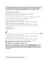
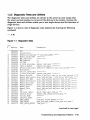
1.3.1 Power-Up Tests
The system runs the power-up tests each time you turn on the system. Mter
successful completion of tests, the system will either enter console mode or
proceed to automatic bootstrap, depending on the HALT action selected by the
user. If HALT action is Default, Halt, or Restart, then the system enters console
mode. If HALT action is Reboot or Restart_reboot, then the system proceeds to
boot. The following example shows a typical display for a system that passes all
tests and then enters console mode.
KA55-A or KA51-A V2.3, VMB 2.14 ..
Performing normal system tests.
74 .. 73 .. 72 .. 71..70 .. 69 .. 68 .. 67 .. 66 .. 65 .. 64 .. 63 .. 62 .. 61. .60 .. 59 ..
58 .. 57 •. 56 .. 55 .• 54 .. 53 .• 52 .. 51. .50 .. 49 .. 48 .. 47 .. 46 .. 45 .. 44 .. 43 . . . .
42 •. 41. .40 •. 39 .• 38 •. 37 .. 36 .• 35 .. 34 .• 33 .. 32 •. 31. .30 .. 29 .. 28 .. 27 ..
26 .. 25 .• 24 .. 23 •. 22 •• 21. .20 .• 19 .. 18 .. 17 •. 16 .. 15 .• 14 .. 13 .. 12 .. 11. .
10 .. 09 •. 08 •• 07 .• 06 .. 05 .• 04 .. 03 ..
Tests completed.
»> •
tt
.. Central Processing Unit (CPU) Name, Firmware Version Number, and Virtual
Memory Boot (VMB) Version Number
.. Read-Only Memory (ROM) Based Diagnostics Countdown
•
Status Message
e
Console Prompt
1-10 Troubleshooting and Diagnosing Problems
The following example shows a typical display for a system that passes all tests
and then enters automatic bootstrap.
KA55-A or KA51-A V2.3, VMB 2.14
Performing normal system tests.
74 .. 73 .. 72 .. 71.. 70 .. 69 .. 68 .. 67 .. 66 .. 65 .. 64 .. 63 .. 62 .. 61..60 .. 59 ..
58 .. 57 .. 56 .. 55 .. 54 .. 53 .. 52 .. 51. .50 .. 49 .• 48 .. 47 .• 46 •. 45 .. 44 .. 43 ..
42 .. 41. .40 .. 39 .. 38 .. 37 .. 36 .. 35 .. 34 .. 33 .. 32 .. 31. .30 •. 29 .. 28 .. 27 ..
26 .. 25 .. 24 •• 23 .. 22 .. 21. .20 .. 19 .. 18 .. 17 .. 16 .. 15 .. 14 .. 13 .. 12 •. 11. .
10 .. 09 .. 08 .. 07 .. 06 .. 05 .. 04 .. 03 ..
Tests completed.
Loading system software.
(BOOT IR5: 0 EZAO)
2..
-EZAO
1. .0 ..
Note ________________________________________
The operating system messages start here, that is VMS ...
If the power-up tests encounter an error, one of the following actions occurs:
For minor errors:
•
If HALT action is set to a boot condition (that is reboot or restart_reboot),
and if a minor error occurs, the system displays an abbreviated error
message and continues to boot as normal.
•
If HALT action is set to Default, Halt or Restart, then the system enters
console mode.
•
The only errors defined as minor are errors in memory that cause pages
to be marked bad in the memory bitmap. There must be enough good
memory left to allow an attempt to bootstrap.
For severe errors:
•
The system always enters console mode regardless of HALT action after it
attempts to complete all tests possible.
Troubleshooting and Diagnosing Problems 1-11
The following example shows a system with a memory error that only affected one
set of memory out of two· sets. Because some memory is still usable, the system
proceeds to automatic bootstrap if the HALT action is set to a boot condition.
KA55-A or KA51-A V2.3, VMB 2.14
Performing normal system tests.
74 .. 73 .. 72 .. 71..70 .. 69 .. 68 .. 67 .. 66 .. 65 .. 64 .. 63 .. 62 .. 61. .60 .. 59 ..
58 .. 57 .. 56 .. 55 .. 54 .. 53 .. 52 .. 51. .50 .. 49 .. 48 .. 47 .. 46 .. 45 .. 44 .. 43 ..
42 .. 41. .40 .. 39 .. 38 .. 37 .. 36 .. 35 .. 34 .. 33 .. 32 ..
? Test_Subtest 40 06
Loop_Subtest=OO
Err_Type=FF
DE_Memory_count_pages.lis
31 .. 30 .. 29 .. 28 .. 27 .. 26 .. 25 .. 24 .. 23 .. 22 .. 21. .20 .. 19 .. 18 .. 17 .. 16 ..
15 .. 14 .. 13 .. 12 .. 11. .10 .. 09 .. 08 .. 07 .. 06 .. 05 .. 04 .. 03 ..
16 MB RAM, SIMM Set (OA,OB,OC,OD) present
Memory Set 0: 04000000 to 04FFFFFF, 16MB, 0 good pages, 32768 bad pages
64 MB RAM, SIMM Set (1E,1F,lG,1H) present
Memory Set 1: 00000000 to 03FFFFFF, 64MB, 131072 good pages, 0 bad pages
Total of 80MB, 131072 good pages, 32768 bad pages, 136 reserved pages
Tests completed.
Loading system software.
(BOOT IR5: 0 EZAO)
2 ••
-EZAO
1..0 ..
o
? Test_Subtest 40 06
Loop_Subtest=OO
Err_Type=FF
DE_Memory_count_pages.lis
Et
16 MB RAM, SIMM Set (OA,OB,OC,OD) present
Memory Set 0: 04000000 to 04FFFFFF, 16MB, 0 good pages, 32768 bad pages
64 MB RAM, SIMM Set (1E,1F,1G,1H) present
Memory Set 1: 00000000 to 03FFFFFF, 64MB, 131072 good pages, 0 bad pages
Total of 80MB, 131072 good pages, 32768 bad pages, 136 reserved pages
o
Operating system messages start here; that is VMS ...
Et Abbreviated error message for memory error
Memory errors normally cause the results of a SHOW MEMORY display to occur
after the tests are completed and before continuing. SHOW MEMORY is the
most useful command to determine which memory SIMMs are bad when memory
errors occur.
1-12 Troubleshooting and Diagnosing Problems
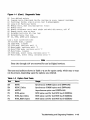
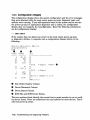
1.3.2 Diagnostic Tests and Utilities
The diagnostic tests and utilities are similar to the power-up tests except that
the power-up tests enable you to test all the devices in the system, whereas the
diagnostic tests and utilities enable you to test single devices and the functions of
single devices.
Figure 1-1 shows a list of diagnostic tests obtained by entering the following
command:
»>
'1' 9E
Figure 1-1 Diagnostic Tests
Test
# Address
30
31
32
33
34
35
37
40
41
42
46
47
48
4A
4B
4C
4D
4E
4F
51
52
53
54
55
56
58
59
20052200
20055850
2006A53C
2006AB34
2005D148
2005D324
2005E6D8
2005FB90
20061590
2006B5EO
20068CEC
20061880
200610C4
2006AD04
2006B028
2006A23C
2006940C
20069BAO
20068FE8
20069188
2006B7F4
2005803C
20058530
20058818
20057C18
20058E6C
2006507C
20065D24
20062778
Name
SCB
De executive
Memory Init Bitmap
Memory-Setup CSRs
NMC registers
NMC-powerup
SSC-ROM
B Cache diag mode
Cache w-Memory
Memory count pages
Board Reset Chk for Interrupts
P Cache-diag mode
Memory Refresh
Memory-Addr shorts
Memory=ECC_SBES
Memory Byte Errors
Memory-ECC Logic
Memory=Address
Memory_Byte
Memory_Data
FPA
SSC Prog timers
SSC-TOY Clock
Virtual-Mode
Interval Timer
SHAC LPBCK
SHAC-RESET
SGEC-LPBCK ASSIST
Parameters
*** mark Hard SBEs ******
*********
**********
**
***
bypass test mask *********
bypass-test-mask *********
SIMM setO SIMM set1 Soft errs allowed *****
*
**********
bypass test mask *********
start a end-incr cant on err time seconds *****
start-add end add * cant-on err pat2 pat3 ****
start-add end-add add incr cant on err ******
start-add end-add add-incr cant-an-err ******
start-add end-add add-incr cant-an-err ******
start-add end-add add-incr cant-an-err ******
start-add end-add add-incr cant on err ******
start-add end-add add-incr cant on err ******
**********
which timer wait time us ***
repeat_test_250ms_ea Tolerance ***
********
*****
From bus To bus passes *******
dssi=bus port_number time secs not_pres *
time sees **
(continued on next page)
Troubleshooting and Diagnosing Problems 1-13
Figure 1-1 (Cont.) Diagnostic Tests
SHAC number *********
5C 20062010 SHAC
loopback type no ram tests ******
5F 200619B8 SGEC
mark not-pre sent-self test rO self test r1 *****
62 20058B1C console QDSS
63 20058CA4 QDSS any
input csr self test rO self test r1 ******
bypass test mask *********
80 200503CO CQBIC memory
IP csr-******
81 200596CC Qbus MSCP
device num addr ****
82 200598AC Qbus-DELQA
controller-number ********
83 2005A85C QZA Intlpbck1
controller-number *********
84 2005BF1C QZA-Intlpbck2
incr test pattern controller number *******
85 20059A9C QZA-memory
86 20059F44 QZA-DMA
Controller number main mem bUf ********
90 20058494 CQBIC registers
*
91 20058410 CQBIC-powerup
**
99 2005DC4C Flush-Ena Caches
dis flush VIC dis flush BC dis flush PC
pass_count disable device *******
9A 20063FBO INTERACTION
**
9B 20068E48 Init memory
9C 2006631C List-CPU registers *
Flags *********
90 2006C250 UtilIty 9E 2005903C List diagnostics
script number *
**********
9F 200681CC Create AO Script
C1 20057888 SSC RAM Data
*
C2 20057A78 SSC-RAM-Data Addr *
*
C5 200589E8 SSC-regIsters
DO 20060C70 V Cache diag mode bypass test mask *********
D2 2005DE90 O-Bit dIag mode
bypass=test=mask *********
**********
DA 2006139C PB Flush Cache
print_speed *********
DB 2005E850 Speed
DC 2006C060 NO Memory present *
OD 2005FOOC B Cache Data debug start add end add add incr *******
DE 2005EC64 B-Cache-Tag Debug start-add end-add add-incr *******
start -add end-add add-incr seg_incr ******
DF 2005E2A8 O-BIT DEBUG-environment reset bus-time s *******
EO 2006D4D4 SCSI E1 2006D7CC SCSI Utility
environment util nbr target ID lun ******
bypass test addr-incr data tst ********
E2 2006DA2C SCSI-MAP
environment *********
E4 2006DFC8 DZ
environment *********
E8 2006E1DC SYNC
E9 2006E2B4 SYNC_Utility
environment *********
EC 2006E398 ASYNC
environment *********
environment reset bus time s *******
FO 2006D638 SCSI option
F1 2006D900 SCSI-Opt Utility environment util nbr target ID lun ******
F2 2006DA40 SCSI=MAP=Option
bypass_test addr-incr data tst ********
Scripts
#
Description
(continued on next page)
1-14 Troubleshooting and Diagnosing Problems
Figure 1-1 (Cont.) Diagnostic Tests
AO
Al
A3
A4
A6
A7
AS
A9
B2
B5
BF
User defined scripts
Powerup tests, Functional Verify, continue on error, numeric countdown
Functional Verify, stop on error, test # announcements
Loop on A3 Functional Verify
Memory tests, mark only multiple bit errors
Memory tests
Memory acceptance tests, mark single and multi-bit errors, call A7
Memory tests, stop on error
Extended tests plus BF, then loop
Extended tests, then loop
DZ, SYNC, ASYNC with loopbacks
Load & start system exerciser
100 Customer mode, 2 passes
101 CSSE mode, 2 passes
102 CSSE mode, continous until AC
103 Manuf mode, continous until AC
104 Manuf TINA mode, continous until AC
105 Manuf mode, 2 passes
106 CSSE mode, select tests, continous until AC
107 Manuf mode, select tests, continous until AC
Note
Tests 101 through 107 are reserved for use by Digital services.
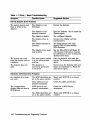
The tests and utilities shown in Table 1-2 are for option cards, which mayor may
not be present, depending upon the options you ordered.
Table 1-2 Option Card Tests
Test
Name
Usage
E8
SYNC
SYNC_Utility
ASYNC
Synchronous COMM option card (DSW41142)
Synchronous COMM option card (DSW41142)
Asynchronous option card (DHW41/42)
Fl
SCSCoption
SCSI_Opt_Utili ty
SCSI option card for 2nd SCSI bus B (KZDDA)
SCSI option card for 2nd SCSI bus B (KZDDA)
F2
SCSCMAP_Option
SCSI option card for 2nd SCSI bus B (KZDDA)
E9
EC
FO
Troubleshooting and Diagnosing Problems 1-15
Note _ _ _ _ _ _ _ _ _ _ __
The following available tests (Table 1-3) are not used on the MicroVAX
3100 Model 85/95; they are used only on the MicroVAX 4000 Model 100A
1l05A, and are listed here to avoid confusion when you see them in the
diagnostic test listing (Figure 1-1 ).
Table 1-3 MlcroVAX 400D-100A/105A Tests
Test
No.
Name
Usage
56
SRAC_LPBCK
Not used on 3100, SRAC option only
58
SRAC_RESET
Not used on 3100, SRAC option only
5C
62
SRAC
console_QDSS
Not used on 3100, SRAC option only
Not used on 3100, QBUS systems only
63
QDSS_any
Not used on 3100, QBUS systems only
81
Qbus_MSCP
Not used on 3100, QBUS systems only
82
83
Qbus_DELQA
QZA_Intlpbck1
Not used on 3100, QBUS systems only
Not used on 3100, QBUS systems only
84
QZA_Intlpbck2
Not used on 3100, QBUS systems only
85
QZA_memory
Not used on 3100, QBUS systems only
86
QZA_DMA
Not used on 3100, QBUS systems only
To run the diagnostic tests, enter either TEST or T followed by the test number.
You can specify optional parameters for some tests, but you would not do so
normally. If you decide to specify optional parameters, then the following
conditions apply:
•
Each test uses up to 10 parameters, no more than 7 may be inputted on a
command line.
Most of these parameters are assigned values automatically by the system.
These parameters are indicated by an asterisk (*) in the parameters column
of Figure 1-1.
•
If a parameter can be assigned a value, the name of the parameter is shown
in the parameters column in Figure 1-1.
1-16 Troubleshooting and Diagnosing Problems
You can use test 9E with the test number as a parameter to show a list of
legal parameters and valid values for the test number. For example, enter T
9E 30 to show a list of legal parameters and valid values for test number 30
(Memory_In it_Bitmap).
•
There is a dependency between some tests.
•
Failures can occur if dependencies between tests are not followed.
•
Any parameter not entered is given a default value. Enter T 9E nn, where
nn is test number to show defaults. During power-up testing or execution of
any script of tests (AO to BF), the values of parameters are determined by the
script, not defaults.
•
You may dump the contents of a script by entering T 9E nn, where nn is a
script to dump. Scripts are always in range of AO to BF (or 0 for the power-up
script).
You must enter three zeros (0) as place holders for the three parameters that
occur before the user-specified parameter, mark_hard_SBEs. The last value (1)
is a parameter. You can then specify the mark_hard_SBEs parameter in the
Memory_Init_Bitmap test as follows:
»> T 30 0 0 0 1
The resulting messages differ, depending on the function of the test or utility.
However, most failing tests cause the system to display error messages similar to
the following:
»> T SF 1
? Test Subtest 5F 18 Loop Subtest=OE Err Type=FF
DE SGEC.lis
Vec=OlOC Prev-Errs=OOOO -Pl=OOOOOOOI
P2=00000000 P3=827DFF03 P4=00000000
P5=00000000 P6=00000000 P7=00000000 P8=00000001
P9=00000000 PIO=OOOOOOOO
rO=00000054 rl=000082E2
r2=00000001
r3=000082FA r4=00008230 r5=00000040
r6=000082E2 r7=20008000
r8=00008000
r9=20140758 r10=13000001 r11=2014044B
EPC=2005721A dser=OOOO cesr=OOOOOOOO icsr=Ol pcsts=F800 pcctl=FC13
cctl=00000007 bcetsts=03AO bcedsts=0400 cefsts=00019200 nests=OO
mmcdsr=00C6C600 mesr=00006000
»>
Write down the error messages before you contact your Digital services
representative.
Troubleshooting and Diagnosing Problems 1-17
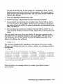
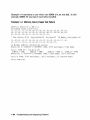
1.3.3 Power-Up Error Messages
The following are examples of some error messages at power-up.
Example 1-1 isa typical example of a failed test. In this case, test E8 failed
testing a SYNC (COMM) option.
Example 1-1 SYNC Test Failure
KA55-A or KA51-A V2.3, VMB 2.14
Performing normal system tests.
74 .. 73 .. 72 .. 71. . 70 .. 69 .. 68 .. 67 .. 66 .. 65 .. 64 .. 63 .. 62 .. 61. .60 .. 59 ..
58 .. 57 .. 56 .. 55 .. 54 .. 53 .. 52 .. 51. .50 .. 49 .. 48 .. 47 .. 46 .. 45 .. 44 .. 43 ..
42 .. 41. .40 .. 39 .. 38 .. 37 .. 36 .. 35 .. 34 .. 33 .. 32 .. 31. .30 .. 29 .. 28 .. 27 ..
26 .. 25 .. 24 .. 23 .. 22 .. 21. .20 .. 19 .. 18 .. 17 .. 16 .. 15 .. 14 .. 13 .. 12 .. 11. .
10 .. 09 ..
? Test Subtest E8 03 Loop Subtest=OO Err Type=FF
DE SYNC.lis
Vec=OOOO Prev-Errs=OOOl -Pl=09000001 P2=OOOOOOOO P3=OOOOOOOO P4=OOOOOOOO
P5=00000000 P6=00000000 P7=00000000 P8=00000000 P9=00000000 PI0=00000000
Stat=0112 FRU=20 LED=OO Ext Stat 00090014 OOEEOOID 00020002 OOOOEFCE 00000000
20040000 7FDEDFFF 00000000 dser=OOOO cesr=OOOOOOOO intmsk=OO icsr=Ol pcsts=F800 pcctl=FC13 cctl=00000021
bcetsts=OOOO bcedsts=OOOO cefsts=00019220 nests=OO mmcdsr=01111000
mesr=00006000
08 .. 07 .. 06 .. 05 .. 04 .. 03 ..
Normal operation not possible.
>>>
1-18 Troubleshooting and Diagnosing Problems
Example 1-2 represents a case where an additional set of memory SIMMs was
added and one of the four SIMMs for the set was not the same type of SIMM
as the others. In this example SIMM 1H was either not installed or incorrectly
installed.
Example 1-2 Memory_Setup_CSRs Test Failure
KA55-A or KA51-A V2.3, VMB 2.14
Performing normal system tests.
74 .. 73 .. 72 .. 71. .70 .. 69 .. 68 .. 67 .. 66 .. 65 .. 64 .. 63 .. 62 .. 61. . 60 .. 59 ..
? Test Subtest 31 05 Loop Subtest=OO Err Type=FF
DE Memory Setup CSRs.lis
Vec=OOOO Prev-Errs=OOOO -P1=00000000 P2=01000000 P3=0000000l P4=00010000
P5=2101801C P6=00000007 P7=80000003 P8=0000CF4A P9=00000001 P10=2006B8D8
rO=00000002 r1=21018000
r2=00000008
r3=81000000
r4=00000001 r5=01000000
r6=2006EB77 r7=21018048
r8=00000000
r9=20140758 r10=00000000 r11=FFFFFFFF
dser=OOOO cesr=OOOOOOOO intmsk=OO icsr=Ol pcsts=FAOO pcadr=FFFFFFF8 pcctl=FC13
cctl=00000020 bcetsts=0360 bcedsts=OFOO cefsts=00019200 nests=OO
mmcdsr=01FE6600 mesr=OOOOOOOO
58 .. 57 .. 56 .. 55 .. 54 .. 53 .. 52 .. 51. .50 .. 49 .. 48 .. 47 .. 46 .. 45 .. 44 .. 43 ..
42 .. 41. .40 .. 39 .. 38 .. 37 .. 36 .. 35 .. 34 .. 33 .. 32 .. 31. .30 .. 29 .. 28 .. 27 ..
26 .. 25 .. 24 .. 23 .. 22 .. 21. .20 .. 19 .. 18 .. 17 .• 16 .. 15 .. 14 .. 13 .. 12 .. 11. .
10 .. 09 .. 08 .. 07 .. 06 .. 05 .. 04 .. 03 ..
16 MB RAM, SIMM Set (OA,OB,OC,OD) present
Memory Set 0: 00000000 to OOFFFFFF, 16MB, 32768 good pages, 0 bad pages
Error: SIMM Set 1 (lE,lF,lG,lH)
SIMM IE = 64MB
SIMM IF = 64MB
SIMM 1G = 64MB
•
SIMM 1H
=
OOMB ??
Total of 16MB, 32768 good pages, 0 bad pages, 104 reserved pages
Normal operation not possible.
•
Indicates no memory SIMM installed here or SIMM not correctly installed.
Troubleshooting and Diagnosing Problems 1-19
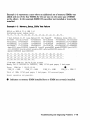
Example 1-3 represents a case where one SIMM of a set was bad. In this
example, SIMM 1G was bad or incorrectly installed.
Example 1-3 Memory_Count_Pages Test Failure
KA55-A or KA51-A V2.3, VMB 2.14
Performing normal system tests.
74 .. 73 .. 72 .. 71. . 70 .. 69 .. 68 .. 67 .. 66 .. 65 .. 64 .. 63 .. 62 .. 61. .60 .. 59 ..
58 .. 57 .. 56 .. 55 .. 54 .. 53 .. 52 .. 51. .50 .. 49 .. 48 .. 47 .. 46 .. 45 .. 44 .. 43 ..
42 .. 41. . 40 .. 39 .. 38 .. 37 .. 36 .. 35 .. 34 .. 33 .. 32 ..
? Test_Subtest 40 06 Loop_Subtest=OO Err_Type=FF
DE_Memory_count_pages.lis
31. .30 .. 29 .. 28 .. 27 .. 26 .. 25 .. 24 .. 23 .. 22 .. 21. .20 .. 19 .. 18 .. 17.. 16 ..
15 .. 14 .. 13 .. 12 .. 11. .10 .. 09 .. 08 .. 07 .. 06 .. 05 .. 04 .. 03 ..
16 MB RAM, SIMM Set (OA,OB,OC,OD) present
Memory Set 0: 04000000 to 04FFFFFF, 16MB, 32768 good pages, 0 bad pages
Error: SIMM Set 1 (lE,lF,lG,lH)
SIMM IE = 64MB
SIMM IF = 64MB
SIMM IG = 64MB?? SIMM IH = 64MB
Memory Set 1: 00000000 to-03FFFFFF, 64MB, 0 good pages, 131072 bad pages
Total of 80MB, 32768 good pages, 131072 bad pages, 136 reserved pages
Tests completed.
1-20 Troubleshooting and Diagnosing Problems
Example 1-4 represents a case where one SIMM of a set is missing or incorrectly
installed. In this case, only one set of SIMMs was installed. Since one was
missing, there is no usable memory for testing to run to completion. SIMM ID is
missing here.
Example 1-4 No_Memory_Present Test Failure
KA55-A or KA51-A V2.3, VMB 2.14
Performing normal system tests.
74 .. 73 .. 72 .. 71..70 .. 69 .. 68 .. 67 .. 66 .. 65 .. 64 .. 63 .. 62 .. 61. .60 ..
? Test Subtest DC 87 Loop Subtest=OO Err Type=FF
DE NO Memory present.lis
Vec=OOOO Prev-Errs=OOOO -P1=EF42EF42
P2=00000000 P3=OOOOOOOO P4=00000000
P5=00000000 P6=7F337F7F P7=00000000 P8=0000EF42 P9=00000001 P10=2006B8D8
rO=00000002 r1=21018000
r2=00000008
r3=00000007
r4=03FFFFEO r5=80000000
r6=FFFFFFFF r7=00000000
r8=00000000
r9=20140758 r10=FFFFFFFE r11=FFFFFFFF
dser=OOOO cesr=OOOOOOOO intmsk=OO icsr=Ol pcsts=FAOO pcadr=FFFFFFF8 pcctl=FC13
cctl=00000020 bcetsts=0360 bcedsts=OFOO cefsts=00019200 nests=OO
mmcdsr=00666640 mesr=OOOOOOOO
Error: SIMM Set 0 (OA,OB,OC,OD)
SIMM OA = 16MB
SIMM OB = 16MB
SIMM OC = 16MB
SIMM OD = OOMB ??
Total of OMB, 0 good pages, 0 bad pages, 0 reserved pages
Normal operation not possible.
Troubleshooting and Diagnosing Problems 1-21
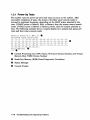
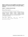
1.3.4 Configuration Display
The configuration display shows the system configuration and the error messages
that were· detected while the most recent power-up tests, diagnostic tests, and
utilities were running. If you add expansion boxes to the system and do not run
the power-up tests or appropriate diagnostic test or utility, the configuration
display does not recognize the reconfiguration. Enter the following command to
see the configuration display:
»> SHOW CONFIG
If the system does not detect any errors in the most recent power-up tests
or diagnostic utilities, it responds with a configuration display similar to the
following:
KASS-A or KAS1-A V2.3, VMB 2.14
08-00-2B-33-CF-C9
80MB
0
TstNbr
.
DevNam
-------CPU BD
0
MEM
A8
E4
DZ
EO
SCSI
o
SF
FO
NI
SCSI B
0
E8
QBUS
COMM
EC
ASYNC
•
Info
-------------------------OK
OK
OK
OK
3-RZ24L
6-Adapter 7-RRD43
OK
OK
O-RZ23L
6-Adapter
OK
OK
DSW41/42 2 CHANNEL V4.10-7b
OK
DHW41/2 VI. 6
•
Test Utility Number Column
.. Device Mnemonic Column
I) Device Status Column
•
SCSI IDs and SCSI Device Names
The test numbers listed identify the normal test or script number to run to verify
the device listed. There are additional tests and utilities for some devices. Test 0
calls the power-up script.
1-22 Troubleshooting and Diagnosing Problems
Note _ _ _ _ _ _ _ _ _ _ __
The lines for FO, E8 and EC display only if the applicable option is
present.
If the system detects errors in the most recent power-up tests and diagnostic
utilities, it responds with a configuration display similar to the following:
KASS-A or KAS1-A V2.3, VMB 2.14
08-00-2B-2B-16-91
80MB
DevNam
-------CPU BD
0
A8
MEMORY
E4
DZ
EO
SCSI
TstNbr
SF
E8
NI
COMM
EC
ASYNC
Info
-------------------------OK
OK
?? 001 0048
OK
3-RZ24L 6-Adapter 7-RRD43
OK
OK
DSW41/42 2 CHANNEL V3.11-47
OK
DHW41/2 Vl. 6
•
»>
•
Error Information-Write down this information before you contact your
Digital services representative.
Troubleshooting and Diagnosing Problems 1-23
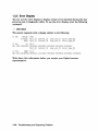
1.3.5 Error Display
You can use the error display to display certain errors detected during the last
power-up test or diagnostic utility. To see the error display, enter the following
command:
»> SHOW ERROR
The system responds with a display similar to the following:
?? 001
CPU BD
B Cache
- NVAX
0000
Test 35
Test-54
Subtest 33
Subtest-OO
Loop sub 27
Loop=sub=Ol
Error type FF
Error=type=FF
?? 001
DZ 0030
010 0001 00000031 00000020 00000000 00000002 00000000 OOOOFIFO
Test_E4 Subtest_02 Loop_sub_OO Error_type_FF
?? 020
COMM 0112
005 0014 001EOOIE OFOF0311 01010002 00000000 0008001E 80000002 00000000
Write down this information before you contact your Digital services
representative.
1-24 Troubleshooting and Diagnosing Problems
1.4 Contacting Digital Services
_ _ _ _ _ _ _ _ _ _ _ Warning
Only authorized service personnel should service the MicroVAX 3100
Model 85/95.
If you have followed the procedures in this chapter but the problem remains
unsolved, your Digital services representative can help you. Before you place
your call, follow these steps:
1. Write down a description of the problem, including the error messages and
the number of the tests or utilities that failed.
2. Look at the status LED display on the back of the system unit and write
down the numbers of the LEDs that are lit (see Figure 1-2).
3. List the steps you took to correct the problem as well and their results.
4. Write down the serial and model numbers of the system unit and any
connected peripheral devices. These numbers are usually printed on a label
on the back of the device.
Troubleshooting and Diagnosing Problems 1-25
Index
c
Cables
checking connections, 1-13
checking the console terminal cable,
1-1
checking the Ethernet cables, 1-2
checking the expansion box power
cords, 1-2
checking the expansion box SCSI
cables, 1-1
checking the system unit power cord,
1-1
checking the terminal power cord, 1-1
troubleshooting, 1-1
Configuration display
error information, 1-23
use of, 1-22
with errors, 1-23
without errors, 1-22
Connections
checking SCSI terminators, 1-2
checking standard Ethernet loopback
connector, 1-2
checking ThinWire Ethernet
terminator, 1-2
Console security feature, 1-9
Console terminal
checking cable, 1-1
checking power cord, 1-1
turning off, 1-1
turning on, 1-2
D
Device mnemonics, 1-22
Device status, 1-22
Diagnostic commands, 1-9 to 1-24
Diagnostic tests, 1-9 to 1-24
Diagnostic tests and utilities, 1-13
listing, 1-13
not applicable, 1-15
option cards, 1-15
optional parameters, 1-16
running, 1-16
typical error display, 1-17
Digital services
contacting, 1-25
E
Error display
use of, 1-24
Error information
in configuration display, 1-23
Ethernet
checking cable, 1-2
Expansion boxes
addition, 1-22
checking power cord, 1-2
checking SCSI cables, 1-1
turning off, 1-1
turning on, 1-2
Index-1
Privileged console mode, 1-9
F
Fan
troubleshooting, 1-3
Field Services
See Digital services
L
Loopbacks
checking, 1-1
checking connections, 1-2
standard Ethernet, 1-1
o
Operating system software
troubleshooting, 1-3
p
Peripherals
turning off, 1-1
turning on, 1-2
Power cord
troubleshooting, 1-3
Power-up
error messages, 1-18 to 1-21
Memory_Count_Pages test failure,
1-20
Memory_Setup_CSRs test failure,
1-19
No_Memory_Present test failure,
1-21
SYNC test failure, 1-18
Power-up display
troubleshooting, 1-3
Power-up tests, 1-22
Halt action variables, 1-10
minor errors, 1-11
severe errors, 1-11
successful display, 1-10, 1-11
unsuccessful display, 1-11, 1-12
use of, 1-10
Index-2
R
RRD43
compact disc drive, 1-5
eject button fault, 1-5
troubleshooting, 1-4
RRD43 compact disc drive
troubleshooting, 1-4
RX26
disk format error, 1-8
diskette drive, 1-7
diskette insertion error, 1-8
eject error, 1-8
head cleaning, 1-8
troubleshooting, 1-7
write-protect error, 1-8
RZ-series SCSI disk drive, 1-8
drive not functional, 1-8
not on configuration display, 1-8
troubleshooting, 1-8
s
SCSI device names, 1-22
SCSI IDs, 1-22
SCSI terminators, 1-2
Security password, 1-9
SHOW CONFIG command
use of, 1-22
SHOW ERROR command
use of, 1-24
Standard Ethernet, 1-2
Status LED display, 1-25
location, 1-26
System unit
checking power cord, 1-1
troubleshooting, 1-3
turning off, 1-1
turning on, 1-2
T
Terminal
troubleshooting, 1-3
Terminators
checking, 1-1
checking connections, 1-2, 1-13
SCSI, 1-2
ThinWire Ethernet, 1-1
Test utility numbers, 1-22
Tests
diagnostic, 1-22
ThinWire Ethernet, 1-2
TLZ06
troubleshooting, 1-6
TLZ07
troubleshooting, 1-6
Troubleshooting, 1-1 to 1-8
RRD43 , 1-4
RX26, 1-7
RZ-series SCSI disk drive, 1-8
system unit, 1-3
table, 1-2
terminal, 1-3
TLZ06, 1-6
TLZ07, 1-6
TZ30, 1-5
TZKI0, 1-7
TZKll, 1-7
TZ30
green LED, 1-6
head cleaning, 1-6
operate lever faults, 1-6
tape drive, 1-5
troubleshooting, 1-5
unload button, 1-6
write-protect error, 1-6
TZKI0
amber LED, 1-7
head cleaning, 1-7
QIC tape drive, 1-7
troubleshooting, 1-7
write-protect error, 1-7
TZKll
QIC tape drive, 1-7
troubleshooting, 1-7
u
Utilities
diagnostic, 1-22
w
Write-protect switch
RX26, 1-8
TZ30, 1-6
TZKI0, 1-7
Index-3
Reader's Comments
MlcroVAX 3100
Model 85/95
Troubleshooting and Diagnostic Information
EK-A0719-TM. 801
Your comments and suggestions help us improve the quality of our publications.
Thank you for your assistance.
I rate this manual's:
Accuracy (product works as manual says)
Completeness (enough information)
Clarity (easy to understand)
Organization (structure of subject matter)
Figures (useful)
Examples (useful)
Index (ability to find topic)
Page layout (easy to find information)
Excellent
0
0
0
0
0
D
0
0
Good
o
o
o
o
o
o
o
o
Fair
0
0
0
0
0
0
0
0
Poor
0
0
0
0
0
0
0
0
I would like to see morelless
What I like best about this manual is
What I like least about this manual is
I found the following errors in this manual:
Page
Description
Additional comments or suggestions to improve this manual:
For software manuals, please indicate which version of the software you are using: _ _
NamefI'jtle
Dept.
Company
Date
Mailing Address
Phone
,
Do Not Tear - Fold Here and Tape
No Postage
Necessary
If Mailed
in the
United States
BUSINESS REPLY MAIL
FIRST CLASS PERMIT NO. 33 MAYNARD MASS.
POSTAGE WILL BE PAID BY ADDRESSEE
DIGITAL EQUIPMENT CORPORATION
Information Design and Consulting
MR01-2/J18 VW
200 FOREST STREET
MARLBORO, MA 01752-3011
1111111111111111111111111111111111111111111111111111
-
Do Not Tear - Fold Here - - - - - - - - - - - - - - - - - - - - - - - - - - - - - - - - - - - - - - -
MicroVAX 31 00
Model 85/95
Installation Information
Order Number: EK-A0716-IN. 801
June 1994
This manual describes how to install and test the MicroVAX 3100
Model 85 and Model 95.
Revision Information:
Digital Equipment Corporation
Maynard, Massachusetts
This manual supersedes EK-A0716-IN. A01
June 1994
Digital Equipment Corporation makes no representations that the use of its products in the
manner described in this publication will not infringe on existing or future patent rights, nor do
the descriptions contained in this publication imply the granting of licenses to make, use, or sell
equipment or software in accordance with the description.
Possession, use, or copying of the software described in this publication is authorized only pursuant
to a valid written license from Digital or an authorized sublicensor.
FCC NOTICE: This equipment has been tested and found to comply with the limits for a Class
A digital device, pursuant to Part 15 of the FCC Rules. These limits are designed to provide
reasonable protection against harmful interference when the equipment is operated in a commercial
environment. This equipment generates, uses, and can radiate radio frequency energy and, if not
installed and used in accordance with the instruction manual, may cause harmful interference to
radio communications.
Any changes or modifications made to this equipment may void the user's authority to operate this
equipment.
Operation of this equipment in a residential area may cause interference in which case the user
at his own expense will be required to take whatever measures may be required to correct the
interference.
Warning!
This is a Class A product. In a domestic environment this product may cause radio interference in
which case the user may be required to take adequate measures.
This warning only applies to the MicroVAX 3100 Model 85.
Achtung!
Dieses ist ein Gerat der Funkstorgrenzwertklasse A. In Wohnbereichen konnen bei Betrieb
dieses Gerates Rundfunkstorungen auftreten, in welchen Fallen der Benutzer fUr entsprechende
GegenmaBnahmen verantwortlich ist.
Diese Warnung bezieht sich nur auf Gerate des Typs MicroVAX 3100 Modell 85.
Attention!
Ceci est un produit de Classe A. Dans un environment domestique, ce produit risque de creer des
interferences radioelectriques, il appartiendra alors a l'utilisateur de prendre les mesures specifiques
appropriees.
Cette mise en garde ne s'applique qu'au MicroVAX 3100 modele 85.
© Digital Equipment Corporation 1994. All Rights Reserved.
The postpaid Reader's Comments form at the end of this document requests your critical evaluation
to assist in preparing future documentation.
The following are trademarks of Digital Equipment Corporation: DEC, Digital, MicroVAX,
OpenVM8, ThinWire, VAX, VAX DOCUMENT, and the DIGITAL logo.
All other trademarks and registered trademarks are the property of their respective holders.
82610
This document was prepared using VAX DOCUMENT Version 2.1.
Contents
Preface................................................
v
1 Installation Procedure
Step 1: Choosing a Suitable Location ......................
Step 2: Unpacking the System and Identifying the Parts. . . . . . .
Step 3: Connecting the Console Terminal ...................
Step 4: Connecting the Thin Wire Terminator ................
Step 5: Connecting the Standard Ethernet Loopback
Connector. . . . . . . . . . . . . . . . . . . . . . . . . . . . . . . . . . . . . . . . . . . .
Step 6: Connecting the Power Cord. . . . . . . . . . . . . . . . . . . . . . . .
Step 7: Turning on the Console Terminal and System Unit. . . . . .
Step 8: Checking the Power-Up Test Results. . . . . . . . . . . . . . . . .
Step 9: Connecting the System to a Network ................
Step 10: Connecting External Options to the System ..........
Step 11: Booting the Operating System. . . . . . . . . . . . . . . . . . . . .
1-1
1-2
1-3
1-4
1-5
1-6
1-7
1-8
1-10
1-10
1-10
Figures
1-1
1-2
Successful Power-Up Test Screen ................ .
Unsuccessful Power-Up Test Screen with an Error
Report .................................... .
1-8
1-9
iii
Preface
This manual describes how to instal1 and test the MicroVAXTM 3100 Model 85 and
Model 95. It also refers to information on connecting the system to a network,
connecting external options to the system, and booting the operating system.
Audience
This manual is intended for anyone who wants to insta]] the MicroVAX 3100
Model 85/95. It is written for both experienced and inexperienced users.
Structure of This Manual
The procedure for instal1ing the MicroVAX 3100 Model 85/95 is presented in only
one chapter. Each section in the chapter represents a major step in the procedure
and contains detailed instructions to fo]]ow.
Additional Information
See the MicroVAX 3100 Model 85195 Operator Information manual for the list of
related documents.
v
Conventions
The following conventions are used in this manual:
Convention
Description
MONOSPACE type
Text displayed on the screen is shown in monospace type.
italic type
Italic type emphasizes important information and indicates the
complete titles of manuals.
Note
A note contains information that is of special importance to the
user.
vi
1
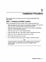
Installation Procedure
This chapter shows you, step by step, how to install the MicroVAX 3100
Model 85/95.
Step 1: Choosing a Suitable Location
Follow these guidelines when you choose where to place the system unit:
•
Place the system unit where the room temperature is between 10°C and 40°C
(50°F and 104°F) and the humidity is between 10% and 90%.
•
Place the system unit at least 1 metre (3 feet) from heaters, photocopying
machines, or other operating equipment.
•
Place the system unit in a well-ventilated location.
•
Place the system unit on a work surface, which is raised above the floor.
•
Keep the air vents on either side of the system unit clear.
•
Do not place the system unit on its side.
• . Do not expose the system unit to direct sunlight or abrasive particles.
Note __________________________________________________________
A console terminal is required for this installation, but is not supplied
with the system. You can order one from your DigitaFM sales
representative.
Installation Procedure 1-1
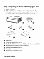
Step 2: Unpacking the System and Identifying the Parts
1. Unpack the system.
2. Make sure that you have all the parts listed on the packing slip. The
following loose-piece accessory kit is shipped with all basic systems. If you do
not have all the parts listed, contact your Digital Sales representative.
o
System Unit
•
DEC423 Terminal Cable (BC 16E-25)
•
One ThinWire™ Ethernet T-Connector (H8223) and Two Terminators (H8225)
•
Standard Ethernet Loopback Connector (12-22196-01)
•
RS232 to DEC423 Adapter (H8575-A)
•
•
Power Cord
Documentation and Software Licenses
1-2 Installation Procedure
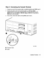
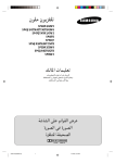
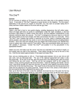
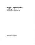
Step 3: Connecting the Console Terminal
1. Connect one end of the tenninal cable to modified modular jack (MMJ) port 3.
2. Connect the other end of the terminal cable to a DEC423 (MMJ)
communications port on the console tenninal. If your terminal has only
RS232 ports, use the RS232 to DEC423 adapter (H8575-A) to provide an
MMJ port on the terminal.
3. If you want, remove the label covering MMJ ports 0 and 1.
MLQ-012030
•
Tenninal Cable
•
Label
Installation Procedure 1-3
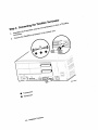
•
T~connector
•
Te1'1ll1natOl"
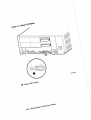
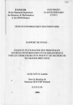
SteP 5: connecting the standard Ethernet
standa~d
connect tbe
conneCtor
unit.
EtbeTt\et \oopbac\t
connecto~
\..oopbac~
~
(12022196001) to tbe S)'ste
~\;,
\ \ "
'.J
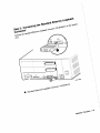
•
.. On/Off switch
•
power cord
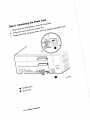
Step· 7: Turning on the Console Terminal and System
Unit
1. Tum on the console tenninal. Wait until it completes its power-up test. (See
the tenninal documentation for more infonnation.)
2. Check the tenninal settings. See the Micro VAX 3100 Model 85/95 Operator
Information manual for the list of correct settings.
3. Turn on the system unit by setting the on/off switch to the on ( I ) position.
MLO-012034
o
On/Off Switch
Installation Procedure 1-7
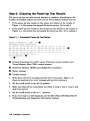
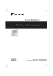
Step 8: Checking the Power-Up Test Results
The power-up test can take several minutes to complete, depending on the
number of installed options you have and on which default settings you use:
•
If the power-up test results on the screen are similar to the results in
Figure 1-1, the system has passed the power-up test. Go to step 9.
•
If the power-up test results on the screen are not similar to the results in
Figure 1-1, the system has not passed the power-up test. Go to substep 1.
Figure 1-1 Successful Power-Up Test Screen
KA55-A or KA51-A V2.3, VMB 2.14
Performing normal system tests.
•
74 .. 73 •. 72 •. 71 .. 70 .. 69 .. 68 .. 67 .. 66 .. 65 •. 64 .. 63 .. 62 .. 61 .. 60 .. 59 ..
58 .. 57 .. 56 •• 55 .• 54 .. 53 .. 52 .. 51. .50 .. 49 .. 48 .. 47 .. 46 .. 45 .. 44 .. 43.. •
42 .. 41. .40 •• 39 .. 38 .. 37 .. 36 .. 35 .. 34 .. 33 .. 32 .. 31. .30 .. ::: 9 .. ::: 8 .. 2, ..
26 .. 25 •• ~ 4 .. 23 .• :2 ~ •• 21 .. :: 0 .. 1 9 .. 18 .. 1 7 .. 16 .. 15 .. 14 .. : ~; .. 1~ .. l1 ..
10 .. 09 .. 08 .. 07 .. 06 .. 05 .. 04 .. 03 ..
Tests completed.
»:-,
••
tt
•
Central Processing Unit (CPU) name, Firmware version number, and
Virtual Memory Boot (VMB) version number
•
Read-Only Memory (ROM) based diagnostics countdown
• Status message
.. Console prompt
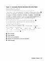
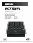
1. Write down the error messages and the error summaries. Figure 1-2
shows an example of an error message and an error summary.
2. Set the on/off switch to the off (0) position.
3. Make sure that all the connections you made in step 3, step 4, step 5, and
step 6 are correct.
4.
Set the on/off switch to the on ( I ) position.
5. If an error report is still displayed, see the MicroVAX 3100 Model 85/95
Troubleshooting and Diagnostic Information manual.
1-8 Installation Procedure
Figure 1-2 Unsuccessful Power-Up Test Screen with an Error Repon
KA55-A or KA51-A V2.3, VMB 2.14
Performing normal system tests.
74 .. 73 .. 72 .. 71 .. 70 .. 69 .. 68 .. 67 .. 66 .. 65 .. 64 .. 63 .. 62 .. 61 .. 60 .. 59 ..
? Test 5ubtest 31 05 Loop Subtest=OO Err Type=FF DE Memory Setup CSRs.lis tt
Vec=OOOO Prev-Errs=OOOO -Pl=OOOOOOOO
F2=01000000 -P3=0000000l -P4=00010000
P5=2101801C P6~00000007 P7=80000003 P8=OOOOCF4A P9=OOOOOOOl PI0=2006B8D8
rO=00000002 rl=21018000 r2=00000008 r3=81000000 r4=00000001 r5=01000000"
r6=2006EB77 r7=21018048 r8=00000000 r9=20140758 r10=00000000 r11=FFFFFFFF
dser=OOOO cesr=OOOOOOOO intmsk=OO icsr=Ol pcsts=FAOO pcadr=FFFFFFF8 pcctl=FC13
cctl=00000020 bcetsts=0360 bcedsts=OFOO cefsts=00019200 nests=OO
mrncdsr=01FE6600 mesr=OOOOOOOO
58 .. 57 .. 56 .. 55 .. 54 .. 53 .. 52 .. 51. .50 .. 49 .. 48 .. 47 .. 46 .. 45 .. 44 .. 43 . . •
4:::: .. 41. .40 .. 39 .. 38 .. 37 .. 36 .. 35 .. 34 .. 33 .. 32 .. 31. .30 .. 29 .. 28 .. 27 ..
26 .. 25 .. :2 4.. 23 .. 22 .. 21. .:2 O.. 19 .. 18 .. 17 .. 16 .. 15 .. 14 .. 13 .. 12 .. 11. .
10 .. 09 .. 08 .. 07 .. 06 .. 05 .. 04 .. 03 ..
16 MB RAM, SIMM Set (OA,OB,OC,OD) present
Set 0: 00000000 to OOFFFFFF, 16MB, 32768 good pages, 0 bad pages
Memo~y
Err-or:
SIr~M
Set 1 (IE, IF, IG,
SIMM IE = 64MB
•
~H)
SIMM IF = 64MB
SIMM IG = 64MB
SIMM IH
=
OOMB
??
Tota: of 16ME, 3::::766 good pages, 0 bad pages, 104 reserved pages
Norma':' ('perati(;rl nc,t possible . •
tt
Error message
.. Error summary
•
Power-up test completion
•
Specific error information on the test that failed
•
Status message
Installation Procedure 1-9
e
~
N
_______________________
_______________________
Step 9 and step 10 are optional. However, step 11 is mandatory.
Step 9: Connecting the System to a Network
If you want to connect the system to a network, see the Micro VAX 3100
Model 85/95 Operator Information manual.
Step 10: Connecting External Options to the System
If you want to connect external options to the system, see the MicroVAX 3100
Model 85/95 Operator Information manual.
Step 11: Booting the Operating System
The system is supplied with factory installed software (FIS) on the system disk.
Boot the operating system following the procedures in the Open VMSTM Factory
Installed Software User Information.
1-10 Installation Procedure
Reader's Comments
MlcroVAX 3100
Model 85195
Installation Information
EK-A0716-IN. B01
Your comments and suggestions help us improve the quality of our publications.
Thank you for your assistance.
I rate this manual's:
Accuracy (product works as manual says)
Completeness (enough information)
Clarity (easy to understand)
Organization (structure of subject matter)
Figures (useful)
Examples (useful)
Index (ability to find topic)
Page layout (easy to find information)
Excellent
0
0
0
0
0
0
0
0
Good
o
o
o
o
o
o
o
o
Fair
0
0
0
0
0
Poor
0
0
0
0
0
0
0
0
0
0
0
I would like to see morelless
What I like best about this manual is
What I like least about this manual is
I found the following errors in this manual:
Page
Description
Additional comments or suggestions to improve this manual:
. For software manuals, please indicate which version of the software you are using: _ _
Nametritle
Dept.
Company
Date
Mailing Address
Phone
· Do Not Tear - Fold Here and Tape
No Postage
Necessary
If Mailed
in the
United States
BUSINESS REPLY MAIL
FIRST CLASS PERMIT NO. 33 MAYNARD MASS.
POSTAGE WILL BE PAID BY ADDRESSEE
DIGITAL EQUIPMENT CORPORATION
Information Design and Consulting
MR01-2/J18 VW
200 FOREST STREET
MARLBORO, MA 01752-3011
1111111111111111111111111111111111111111111111111111
-
Do Not Tear - Fold Here - - - - - - - - - - - - - - - - - - - - - - - - - - - - - - - - - - - - - - -