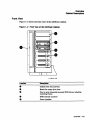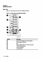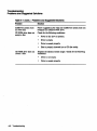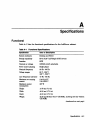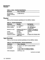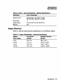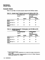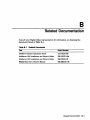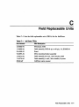
1
InfoTower
Installation and Operating Information
Order Number: EK-INFOE-OM.801
First Printing, February 1993
SecoDd Edition, April 1993
The information in this document is subject to change without notice and should not be
construed as a commitment by Digital Equipment Corporation. Digital Equipment Corporation
assumes DO responsibility for any errors that may appear in this document.
The software described in this document is furnished under a license and may be used or copied
only in accordance with the terms of such license.
No responsibility is assumed for the use or reliability of software on equipment that is not
supplied by Digital Equipment Corporation or its afiiliated companies.
Restricted Rights: Use, duplication, or disclosure by the U.s. Government is subject to
restrictions as set forth in subparagraph (c) (1) (ii) of the Rights in Technical Data and
Computer Software clause at DFARS 252.227·7013.
C Digital Equipment Corporation 1993.
All Rights Reserved.
The following are trademarks of Digital Equipment Corporation: DEC, Digital, RRD42, and the
DIGITAL logo.
All other trademarks and registered trademarks are the property of their respective holders.
This document was prepared using VAX DOCUMENT, Version 2.1.
Contents
Preface .....................................................
vii
1 Overview
Features. . . . . . . . . . . . . . . . . . . . . . . . . . . . . . . . . . . . . . . . . . . . . . . . . .
Cabinet Description . . . . . . . . . . . . . . . . . . . . . . . . . . . . . . . . . . . . . . . ..
Front View . . . . . . . . . . . . . . . . . . . . . . . . . . . . . . . . . . . . . . . . . . . . .
Rear'View .............................................
'
1-1
1-2
1--3
1-4
2 Installation
Summary of Installation .....................................
Step One: Position the InfoTower. .. . . . . . .. . . . . . . . . . . . . . . . . . . . . .
Choosing the Right Location ...............................
Unpacking the Boxes . . . . . . . . . . . . . . . . . . . . . . . . . . . . . . . . . . . . .
Determining InfoTower Power ReqUirements. . . . . . . . . . . . . . . . . . .
Step Two: Verify InfoTower Cabinet Components. . . . . . . . . . . . . . . . . . .
Step Three: Prepare for the Installation. . . . . . . . . . . . . . . . . . . . . . . . . .
Step Four: Connect the Power Cable. ...........................
Step Five: Connect SCSI Cables for InfoServer 100 System. . . . . . . . . . .
Step Six: Connect SCSI Cables for InfoServer 150 System. . . . . . . . . . . .
Step Seven: Connect other External Devices. .....................
Step Eight: Tum on the Power to the lnfoTower Cabinet. .. . . . . . . . . . .
Step Nine: Tum on the Power to the InfoServer System. ............
Step Ten: Verify Drive Access. . . . . . . . . . . . . . . . . . . . . . . . . . . . . . . . . .
2-1
2-1
2-2
2-2
2--3
2-3
2-4
2-5
2-6
2-10
2-13
2-15
2-15
2-15
iii
3 Adding Additional SCSI Drives
Configu.ring Drives . . . . . . . . . . . . . . . . . . . . . . . . . . . . . . . . . . . . ... . . . .
Inserting Drives . . . . . . . . . . . . . . . . . . . . . . . . . . . . . . . . . . . . . . . . . . . .
Removing Drives . . . . . . . . . . . . . . . . . . . . . . . . . . . . . . . . . . . . . . . . . . .
3-1
3-2
3-5
4 Troubleshooting
Problems and Suggested Solutions. . . . . . . . . . . . . . . . . . . . . . . . . . . . . .
4-1
A Specifications
Functional . . . . . . . . . . . . . . . . . . . . . . . . . . . . . . . . . . . . . . . . . . . . . . . .
Physical . . . . . . . . . . . . . . . . . . . . . . . . . . . . . . . . . . . . . . . . . . . . . . . . . .
Input Electrical . . . . . . . . . . . . . . . . . . . . . . . . . . . . . . . . . . . . . . . . . . . .
Output Electrical . . . . . . . . . . . . . . . . . . . . . . . . . . . . . . . . . . . . . . . . . . .
Acoustic Values ............................................
A-1
A-2
A-2
A-3
A--4
B Related Documentation
C Field Replaceable Units
Index
Examples
2-1
2-2
Display for InfoServer System ....................... .
SHOW DEVICE Display ........................... .
2-15
2-16
lnfoTower Cabinet . . . . . . . . . . . . . . . . . . . . . . . . . . . . . . . . .
Front View of the InfoTower Cabinet .................. .
Rear View of the InfoTower Cabinet ................... .
InfoServer 100 System with an InfoTower Cabinet ....... .
Connecting InfoTower to an InfoServer 100 System ....... .
InfoServer 150 System with an InfoTower Cabinet ....... .
Connecting InfoTower to an InfoServer 150 System ....... .
Connecting Two InfoTowers to an InfoServer 150 System .. .
1-2
Figures
1-1
1-2
1-3
2-1
2-2
2-3
2-4
2-5
iv
1-3
1--4
2-7
2-8
2-10
2-11
2-13
2~
3-1
3-2
3-3
Connecting Extemal Devices to the InfoTower Cabinets ... .
Drive Mounting Bracket ........................... .
Properly Seating Drives . . . . . . . . . . . . . . . . . . . . . . . . . . . . .
Driver Frame ~ver . . . . . . . . . . . . . . . . . . . . . . . . . . . . . . . .
2-14
3-3
3-4
3-5
Drive Switch Settings for the InfoServer 100 System ..... .
Drive Switch Settings for the InfoServer 150 System ..... .
Drive Switch/Jumper Settings ...................... .
Problems and Suggested Solutions .................... .
Functional Specifications ........................... .
Physical Specifications . . . . . . . . • . . . . . . . . . . . . . . . . . . . . .
Input Charaeteristics - Electrieal Specifications .......... .
Output Characteristics - Eleetriea1 Specifications ........ .
Acoustic Values! (Declared Values per ISO 9296 and ISO
7779) .......................•..•............ ~ ...
Schallemissionswerte1 CWerteangaben nach ISO 9296 und
ISO 7779IDIN EN27779) ........................... .
Related Documents ...
InfoTower FRUs . . . . . . . . . . . . . . . . . . . . . . . . . . . . . . . . . . .
2-9
2-12
Tables
2-1
2-2
3-1
4-1
A-1
A-2
A-3
A-4
A-5
B-1
C-1
0 • • • • • • • • • • • • • • • • • • • • • • • • • • • • •
3-1
4-1
A-1
A-2
A-2
A-3
A-4
B-1
C-1
v
Preface
This guide describes how to install and troubleshoot the InfoTower cabinet. It
also contains configuration rules and management information.
Organization
This manual contains four chapters and two appendixes.
Chapter 1, Overview-Describes the features of the InfoTower cabinet. It
identifies and describes the cabinet components.
Chapter 2, Installation-Describes the configuration rules for connecting an
Inf01'ower cabinet to an lnfoServer 100 or 150 system. It describes two types
of physical configurations: desktop and tower. It describes how to position the
unit, prepare the unit for installation, connect the cables, and power up the
Inf01'ower cabinet and InfoServer system.
Chapter 3, Adding Additional SCSI Drives-Describes how to add
additional drives to the system.
Chapter 4, Troubleshooting-Describes problems and lists the suggested
solutions. It includes installation and removal information on CD ROM drives.
Appendix ~ Speci:fications-Contains the electrical and mechanical
specifications for operating the expander cabinet.
Appendix B, Related Documentation-Contains a listing of related
documents and ordering information.
Appendix C, Field Replaceable Units-Contains a listing of the field
replaceable units (FRUs).
vii
Conventions
The following conventions are used in this guide:
Convention
Meaning
Note
Caution
WarniDg
bold test
Provides general information.
para.meters
[]
Provides information to prevent damage to equipment and software.
Provides information to prevent personal injury.
Bold text represents user input. For example:
DECbridge> Set Protocol
Parameters are italicized. For example:
SHOW PORT slot number
Gharacters within brackets represent optional parameters. For
example:
.
SHOW PORT [hub number, slot number]
Symbol for caution.
Symbol for fault.
viii
1
Overview
This chapter lists the features and components of the InfoTower cabinet.
Figure 1-1 shows the InfoTower cabinet.
.
Features
The features of the InfoTower are as follows:
•
InfoServer-1OO and
InfoServer-150 compatible
•
Eight SCSI drive bays
•
Desktop and tower
configurations
•
Locked environment for SCSI drives
•
Quick and easy installation and removal of
drives
•
Hinged, see-through cabinet door
•
200 watt power supply system
Overview 1-1
Overview
cabinet Descrtptlon
Cabinet Description
The InfoTower cabinet is a hardware-only product. It provides additional SCSI
drive capacity for either an InfoServer 100 or InfoServer 150 system. You can
access SCSI drives in the Info'lbwer as you would internal InfoServer system
drives.
Figure 1-1 InfoTower cabinet
LJ·02UO·TIO
1-2 Overview
Overview
cabinet Description
Front View
Figure 1-2 shows the front view of the InfoTower cabinet.
Figure 1-2 Front View of the InfoTower cabinet
LJ-02S13-TlO
Location
••
•
•.
Description
Cabinet door lock and keys
Bezels for empty drive slots
One to seven internally-mounted SCSI drives, including
mounting frames
SCSI internal connector
Power interface
OVerview 1-3
Overview
cabinet Description
Rear View
Figure 1-3 shows the rear view of the InfoTower cabinet.
Figure 1-3 Rear View of the InfoTower cabinet
LJ·02648-TIO
location
••
•
••
••
1-4 Overview
Description
Exterior SCSI interface port with terminator
Power supply on/off switch
Fan
Exterior SCSI interface port without terminator
Internal SCSI backplane
de power backplane
ac voltage select
2
Installation
This chapter describes how to install the lnfoTower cabinet.
Summary of Installation
The following summarizes the steps to install an InfoTower cabinet. Each of
these steps is described in more detail in the sections that follow:
1. Position the Info'lbwer
2. Verify InfoTower cabinet components
3. Prepare for the installation
4. Connect the power cable
5. Connect the SCSI cables for the lnfoServer 100 system
6. Connect the SCSI cables for the lnfoServer 150 system
7. Connect other extemal devices
8. Tum on the power to the InfoTower cabinet
9. Tum on the power to the InfoServer system
10. Verify SCSI drive access
Step One: Position the InfoTower.
Due to the length of the SCSI cable (three-foot cable) and the power cable,
position the InfoTower cabinet within three feet of the InfoServer system and
within the length of the power cable to a power source outlet.
Installation 2-1
Installation
Step One: Position the InfoTower.
Choosing the Right Location
Use the following guidelines to choose the best location for your InfoTower
cabinet. Choosing an optimal operating environment is crucial in keeping your
system operating at its best.
•
Carefully read all installation instructions before you tum on the power.
•
Keep the temperature between 10 to 35 degrees C (50 to 98 degrees F).
•
Keep the relative humidity between 10 to 85 percent.
•
Keep the air well circulated to prevent excess heat and dust from
accumulating.
•
Keep your equipment away from heaters, photocopiers, direct sunlight, and
abrasive particles.
•
Before you set up your system, select a surface that is large enough to hold
the system unit. Your desk or work table is a good choice.
•
Keep the area clean. Do not place food or liquid on or near your equipment,
and do not place your system unit directly on the fioor. Dust and dirt will
damage the system components.
•
Keep air vents clear on the front and rear of the system unit for proper
ventilation. Blocking the air vents can cause the system unit to overheat.
•
Connect your system to a dedicated grounded
•
If you have several pieces of equipment that need to be plugged into an
electrical outlet, then use a grounded power strip. Many power strips come
with an on/off switch and a surge protector.
Do not exceed the circuit power capacity.
•
To avoid damaging equipment that has been moved inside from a cold
environment, let the equipment warm to room temperature before you tum
on the power.
eireuit~
Unpacking the Boxes
_____________________ camlon _____________________
Because of the weight of the system unit, 56lbs (25.45 kg), two people
should lift the equipment out of the shipping carton and place it on a
work surface.
When unpacking the boxes, keep the contents of each box separate from the
others.
2-2 Installation
Installation
Step One: Position the InfoTower.
Determining InfoTower Power Requirements
The InfoTower cabinet uses a standard switch selectable 110/220 V, 50160 Hz,
ac power source. To protect the InfoTower and its internal components, you
should use an approved surge suppresser between the power source and the
cabinet.
Step Two: Verify InfoTower Cabinet Components.
After you have selected a proper location for the InfoTower cabinet and have
carefully unpacked the box contents, check that all components have been
included in the shipment. Verify that the number and types of SCSI drives
mounted in the cabinet correspond to the order number and types of drives
that were ordered.
Ensure that the accessories bag contains the following items:
•
Two keys
•
Four rubber feet
•
One power cord
•
Two extemal SCSI cables: BCS6H-03, and BCl9J-03
•
One terminator
•
One template (guide showing how to position the feet)
•
InfoTower Installation a.nd Operating Information
• RRD42 Disc Drive Owner's Manual,
•
Four or seven CD ROM caddies
Installation 2-1
Installation
Step Three: Prepare for the Installation.
Step Three: Prepare for the Installation.
To prepare for the installation of the InfoTower cabinet, perform the following
steps:
1. Make sure that all users terminate their sessions on the InfoServer system.
If there are users on the system, then lock out any subsequent accesses
by entering the SET SERVER STATE SHUT command at the InfoServer
system console.
____________________
Ca~ion
____________________
Never install or remove SCSI drives if the power to either the
InfoTower cabinet or InfoServer system is on. Doing so can crash the
InfoServer system and cause damage to any attached devices, including
SCSI drives in the InfoTower cabinet.
2. Tum the power off on the InfoServer system.
3. Tum the power off on any connected extemal devices.
4. Move the InfoTower cabinet into the desktop or tower (vertical) position.
__________________ Warning _____________
For the vertical installation of the lnfoTower, use an enclosure
mounting stand.
_______________ W8mung ___________
Bei der vertikalen installation des InfoTowers, verwenden Sie einen
Stander fUr das Gehiuse.
_______________
Avenl~eM
___________
Pour une installation veticale de I'InfoTower, utilisez un pied pour
soutenir Ie boitier.
200004 Installation
Installation
Step Three: Prepare for the Installation.
____________ Culc:lado _______________
Para instalaci6n vertical de la InfoTower usa usted una plataforma
montada en un recinto.
For desktop orientation, use the template to attach the four rubber feet.
5. Unlock and open the cabinet door. Remove the protective insert. Save the
insert for future shipping.
_____________________
N~e
____________________
When setting up a desktop unit, remove the key after unlocking the
door so that it will open completely.
6. Visually inspect each SCSI drive to ensure that it is seated properly. See
Figure 3-2 and Figure 3-3.
Step Four: Connect the Power Cable.
_____________________ camion ____________________
Check the setting of the voltage select switch and ensure that it
matches your site requirements.
To connect the power cable:
1. Locate and remove the label over the power connector.
2. Check the power switch setting.
3. Plug in the power cable.
Installation 2-5
Installation
Step Five: Connect SCSI cables for InfoServer 100 System.
Step Five: Connect SCSI Cables for InfoServer 100 System.
______________________
N~e
______________________
If you have an lnfoServer 150 system, proceed to Step SiX: Connect
SCSI Cables for the InfoServer 150 system.
The InfoServer 100 system has one internal hard drive and up to two internal
CD-ROM drives. The internal hard disk and one of the CD-ROM drives reside
on the A bus. The second CD-ROM drive, if present, resides on the B bus.
Up to six additional SCSI devices can be added to the B bus. The six external
devices can be anyone of the following combinations:
•
Six SCSI drives in the InfoTower cabinet
•
A combination· of SCSI drives in the InfoTower cabinet and external SCSI
devices
Figure 2-1 shows the InfoServer 100 system with the InfoTower in the desktop
and tower configurations.
The InfoTower cabinet Uses a BCl9J-03 cable to connect to the InfoServer
100. You connect one end of the cable to the SCSI port on the back of the
InfoTower cabinet and the other end to the external SCSI port on the back of
the InfoServer 100.
2~
Installation
Installation
Step Five: Connect SCSI Cables for InfOServer 100 System.
Figure 2-1 InfoServer 100 System with an InfoTower cabinet
l
l
............
\::1
-
Tower Configuration
_.
.....
[I
I
Ll
~o
_ C•
-c:
_c::
a-C::
1
[\
III~I~~~~~
---
I
-
Desktop Configuration
Installation 2-7
Installation
Step Five: Connect SCSI cables for InfoServer 100 System.
Figure 2-2 shows the connections from an InfoTower cabinet to an InfoServer
100 system. The InfoServer 100 has two SCSI buses: A and B. The A bus
cannot be expanded. The B bus can be expanded using the external SCSI port.
When setting the SCSI address, refer to Table 2-1.
______________________
N~e
______________________
You can use one of the two external SCSI connectors on the rear of the
InfoTower cabinet to connect the InfoTower to the InfoServer system.
The other connector can be used to connect external devices.
Figure 2-2 Connecting InfoTower to an InfoServer 100 System
LJ-02644·TIO
2-8 Installation
Installation
Step Five: Connect SCSI cables for InfoServer 100 System.
Table 2-1 lists the drive switch settings for the InfoServer 100 system.
Table 2-1 Drive Switch Settings for the InfoServer 100 System
SCSI
Device
Bus
Address
Description
DKO:
DK1:
DK2:
DK3:
DK4:
OK5:
DKS:
OK7:
DKO:
DK1:
DK2:
DK3:
OK4:
OK5:
OKS:
OK7:
A
A
A
A
A
A
A
0
Not available
1
2
Hard disk
Internal CD ROM drive
3
Not available
4
Not available
Not available
SCSI controller
A
B
B
B
B
B
B
B
B
5
S
7
0
1
2
3
4
5
6
7
Not available
Available
Available
Available
Available
Available
Internal CD ROM drive
SCSI controller
Available
Installation 2-9
Installation
Step Six: Connect SCSI Cables for InfoServer 150 System.
Step Six: Connect SCSI Cables for InfoServer 150 System.
The InfoServer 150 system contains an internal hard disk and one CD-ROM.
Figure 2-3 shows the InfoServer 150 system with the InfoTower in the desktop
and tower configurations.
Figure 2-3 InfoServer 150 System with an InfoTower cabinet
Tower Configuration
~-.
I
to -
O..ktop Configuration
2-10 Installation
• mJ
I
"", __no
Installation
Step Six: Connect SCSI cables for InfoServer 150 System.
When setting the SCSI addresses, refer to Table 2-2.
Table 2-2 Drive Switch Settings for the InfoServer 150 System
Device
Bua
DKO:
DK1:
DK2:
DK3:
DK4:
DKS:
DK6:
DK7:
DKO:
A
A
A
A
A
A
A
A
B
B
B
B
B
B
B
B
DKl:
OK2:
OK3:
OK4:
DKS:
DKS:
DK7:
2-12 Installation
SCSI
Addr_
0
1
2
3
4
5
6
7
0
1
2
3
Description
Available
Internal bard disk
Intemal CD ROM drive
Available
Available
Available
SCSI controller
Available
Available
Available
Available
Available
4
5
6
Available
Available
7
Available
SCSI controller
Installation
Step Six: Connect SCSI cables for InfoServer 150 System.
Figure 2-5 shows two InfoTower cabinets connected to the InfoServer 150
system.
Figure 2-5 Connecting Two InfoTowers to an InfoServer 150 System
LJ-02645-TIO
Step Seven: Connect other External Devices.
_______________________
N~e
_______________________
You can use one of the two external SCSI connectors on the rear of the
InfoTower cabinet to connect the InfoTower to the InfoServer system.
The other connector can be used to connect external devices.
Figure 2-6 shows the external SCSI connectors on the InfoTower cabinets.
Connect the InfoTower cabinets directly to the InfoServer system. Connect the
extemal devices to the InfoTower cabinets_ You must assign a unique SCSI ID
address to each device on the SCSI bus. The order of devices does not matter,
except with a tape drive,' which should be the last device in the chain. You
must terminate the last device on the bus.
Installation 2-13
Installation
Step Seven: Connect other External Devices.
Figure 2-6 Connecting External Devices to the InfoTower cabinets
To External
Device
To InfoServer
System
LJ·02647·TIO
To connect other external devices, perform the following steps:
1. Make sure that the SCSI addresses of the external devices do not conflict
with the labeled addresses of the SCSI drives contained in the InfoTower
cabinet.
2. Remove the terminator from the SCSI port on the back of the InfoTower
cabinet that is not connected to the InfoServer system.
3. Connect the SCSI cable attached to the first external device in the chain to
the SCSI port on the InfoTower cabinet.
4.
Check. other connections in the chain to ensure the connections are secure
and that the last device in the chain is terminated.
2-14 Installation
Installation
Step Eight: Turn on the Power to the InfoTower cabinet.
Step Eight: Turn on the Power to the InfoTower Cabinet.
'fum the power on to the cabinet. The power switch is located near the fan
at the rear of the cabinet. Tum the power on to any attached external SCSI
devices.
Step Nine: Turn on the Power to the InfoServer System.
'fum on the power to the InfoServer system. Example 2-1 shows the
InfoServer .system console displays. When booting is complete, a password
prompt will appear on the console. Refer to Chapter 4 if the system fails to
boot.
Example 2-1 Display for InfoServer System
KA41-2 Vl.O
F •. E •.• D••. C•.. B .•• A ..• 9 .. 8 ••. 7 ... 6 ... 5 •.. 4_ •• 3_ .• 2_ .. 1. ..
?-E 0040 0000.0005
? C 0080 0000.4001
-
83 BOOT SIS
-DKAlOO
DEC InfoServer 150
Copyright (c) 1991 Digital Equipment Corporation
%ESS-I-INITDisc, Disc Initialization complete, 14 devices found
Step Ten: Verify Drive Access.
At the InfOServer system console, enter the SHOW DEVICE command to
ensure that all of the connected drives are accessible by the InfoServer system.
Example 2-2 shows the SHOW DEVICE command display.
Installation 2-15
Installation
Step Ten: Verify Drive Access.
Example 2-2 SHOW DEVICE Display
InfoServer> show device
Device Device
Device
Device
Name
State
Type
Address
DKl:
On
Hard Disk
A/OOl
DK2:
On
Compact Disc A/002
DK8:
On
Compact Disc B/OOO
019:
On
Compact Disc B/OOl
OKlO:
On
Compact Disc B/002
DKll:
On
Compact Disc B/003
DKl2:
On
Compact Disc B/004
DKl3:
On
Compact Disc B/OOS
DKlS:
On
Compact Disc B/007
Dev. Size/
Record Num.
237588
0
891672
1218000
400780
891680
1218000
0
1171212
Volume
Label
ON!NOWN
Ol?TMOD
CDDOC04MAR21
SMC
CD DOC 82861
CDDoc04MAR22
UNI<NOWN
If all the devices are displayed, then there are no SCSI m conflicts. Refer to
Chapter 4 if any of the the SCSI drives are not displayed.
The InfoTower is manufactured with device addresses starting at address
000. The address 000 unit is always placed either in the front bottom slot, if
positioned in the tower orientation, or in the front right most slot, if positioned
in the desktop orientation.
Device addresses increment by one, up to the maximum number of devices in
the enclosure. Address 006 does not increment by one, because it is reserved
for the system controller~
2-16 Installation
3
Adding Additional SCSI Drives
This chapter describes how to add additional drives to the InfoServer system
and InfoTower cabinet. (The H056-drive mounting bracket option is purchased
separately.)
_______________________ Note _______________________
The power supply used in the InfoTower requires a minimum load 'of
3A on the +5V source for proper regulation. Ensure that the devices
installed in the cabinet present a load to satisfy this requirement. ,',
Configuring Drives
When configuring a drive, refer to the configuration information provided
with the drive. SCSI device addresses are generally set in accordance with
Table 3-1. Always tum the power off before installing the drive. Always check
to see which device addresses are in use before adding devices.
Table 3-1 Drive Switch/Jumper Settings
Device
Address
101
102
103
0
0
0
0
1
1
0
0
2
0
1
0
1 =On/In
0= Oft7Out
(continued on next page)
Adding Additional SCSI Drives 3-1
Adding Additional SCSI Drives
Configuring Drives
Table 3-1 (Cont.) Drive SwitcblJumper Settings
Device
Address
101
ID2
103
3
1
1
0
4
0
0
1
5
1
1
6
N/A
0
N/A
N/A
7
1
1
1
1 = OnIIn
0= Offi'Out
Insening Drives
With the power off to both the InfoServer system and InfoTower cabinet,
perform the following steps to insert a drive into the InfoTower cabinet:
1. Check that the SCSI ID jumper/switches are set correctly.
2. Mount the SCSI device into the drive mounting bracket as follows:
a. Position the SCSI device into the drive mounting bracket as shown in
Figure 3-1.
3-2 Adding Additional SCSI Drives
Adding Additional SCSI Drives
Inserting Drives
Figure 3-1 Drive Mounting Bracket
LJ -02Sn-TIO
________________________ Note ________________________
The installation of non-Digital or Digital qualified devices in
combinations not tested by Digital, may result in configurations that do
not comply with EMC regulations or product safety requirements.
b. Connect the 50-pin SCSI cable to the SCSI device.
c.
Plug the dc power connector into the SCSI device.
d. Position the SCSI device such that the screw holes of the device and
the bracket line up. Use the appropriate screws to attach the drive
mounting bracket to the SCSI device.
3. Unlock and open the InfoTower cabinet door.
4. Remove a bezel, if necessary, and align the drive mounting frame with any
vacant drive slot within the InfoTower cabinet_
Adding Additional SCSI Drives 3-3
Adding Additional SCSI Drives
Inserting Drives
5. Gently push the drive into the vacant slot until its front face is Hush with
all other drives in the InfoTower cabinet as shown in· Figure 3-2.
Figure 3-2 Properly seating Drives
6. To ensure propel' SCSI bus and power connectivity, cheek to see that the
drive frame level' is in position and that the drive is locked into its slot as
shown in Figure 3-3.
3-4 Adding Additional SCSI Drives
Adding Additional SCSI Drives
Inserting Drives
Figure 3-3 Driver Frame Lever
7. Tum the power on for both the InfoServer system and the InfoTower.
Removing Drives
_______________________ Note _______________________
Eject any removable media from the drive before performing the
following procedures.
With the power off to both the InfoServer system and InfoTower cabinet,
perform the following steps to remove a drive from the InfoTower cabinet:
1. Unlock and fully open the InfoTower cabinet front door.
2. To release and remove the SCSI device, move the drive frame lever to the
left (Figure 3-3).
3. Hold onto the lever and the exterior of the drive and gently pull the drive
out of the InfoTower cabinet.
Adding Additional SCSI Drives 3-5
Adding Additional SCSI Drives
Removing Drives
4. To remove the SCSI device from the drive mounting bracket, perform the
following steps: .
a. Remove the screws on the sides of the bracket holding the SCSI device
in place.
h. Disconnect the 50-pin SCSI cable and unplug the dc power connector
as shown in Figure 3-1.
3-6 Adding Additional SCSI Drives
4
Troubleshooti ng
This chapter describes how to troubleshoot the InfoTower cabinet.
Problems and Suggested Solutions
Table 4-1 lists problems and suggested solutions when troubleshooting an
InfoTower cabinet:
Table 4-1 Problems and Suggested Solutions
Problem
Solution
Info'lbwer does not
power on (fan is not
Check the following:
turning).
•
Power connections to InfoTower cabinet and power
source.
•
Power outlet at power source with another device.
If the problem still exists, then perform the following:
•
Replace ac power cable.
•
Replace power supply unit.
InfoServer system
boot process does not
recognize an installed
SCSI drive.
Check the SCSI ID jumper settings. If the problem still
exists, then power up the Info'Ibwer and InfoServer system
and reboot the system.
InfoServer system does
not recognize the bus.
Check the following:
•
Bus termination.
•
SCSI cable connection.
•
Power to InfoTower cabinet.
(continued on next page)
Troubleshooting 4-1
Troubleshooting
Problems and Suggested SoluUons
Table 4-1 (Cont.) Problems and Suggested Solutions
Problem
Solution
InfoServer system does
not boot fully.
Follow suggestions for when the InfoServer system does not
recognize an installed SCSI drive.
Check for the following conditions:
CD ROM drive does not
accept a disc.
CD ROM drive does not
return a disc.
4-2 Troubleshooting
•
Power to the drive is present.
•
Drive is empty.
•
Drive is seated properly.
•
Disc is properly inserted into a CD disc caddy.
Depress the ejection button longer. Check for the following
conditions:
•
Drive is not empty.
•
Drive is seated properly.
A
Specifications
Functional
Table A-llists the functional specifications for the InfoTower cabinet.
Table A-1 Functional Specifications
Specification
Value or Description
System enclosure
Desktop and Tower
Storage capability
Seven 5.25" half-height SCSI devices
Interface
SCSI
Nominal ac voltage
1201240 switch selectable
Power source phasing
Single phase
Nominal frequency
50Hz-60Hz
Voltage ranges
90 V -135 V
180 V - 265 V
Line frequency tolerance
47 Hz - 63 Hz
Maximum ac running
5A@115 V
3A@230V
current
Maximum power
consumption
307W
Height
17.78 em (7.0 in)
Width
43.18 em (17.0 in)
Depth
43.18 em (17.0 in)
Weight
25.45 kg (56 lbs) with 7 CD ROMs; 15.45 kg (34 lbs) without
CD ROMs
(continued on next page)
Specifications A-1
Specifications
Functional
Table A-1 (Cont.) Functional. Specifications
Specification
Value or Description
Non-condensing
maximum operating
altitude
2.4 KM: (8000 feet)
Physical
Table A-2 lists the physical specifications for the InfoTower cabinet.
Table A-2 Physical Specifications
Specification
Operating
Non.()perating
Ambient temperature
10 - 35 degrees C
-40 - 66 degrees C
Relative humidity
10% - 85%
10% - 95% (packaged)
non-condensing
Maximum wet bulb
28 degrees C (82 degrees F) 32 degrees C (90 degrees F)
(packaged) (non-condensing)
(non-condensing)
Altitude
8,000 feet
16,000 feet
Heat dissipation
1,050 BTUIh
N/A
Temperature gradient
11 degrees CIhr (20
degrees FIhr)
20 degrees CIhr (36 degrees FIhr)
Input Electrical
Table A-3 lists the input electrical specifications for the lnfoTower cabinet.
Table A-3 Input Characteristics • Electrical Specifications
Specification
Value or Description
Line voltage
90 - 135 V
Line frequency
47 -63 Hz
Line current
8 A max.
6 A max.
Power consumption
60 W
@
8C,
179 - 265 V ac (switch selectable)
@ 90 V ac including 3A auxiliary
@ 180 V ac including 2A auxiliary
min. load
(continued on next page)
A-2 Specifications
Specifications
Input Electrical
Table A-3 (Cont.) Input Characteristics - Electrical Specifications
SpecHication
Value or Description
Apparent power
462 VA @ max. load, 120 V ac range
507 VA @ max. load, 220 V ac range
Power factor
.5
Inrush current
13.6 A @ 120 V ac, 9.9 A @ 220 Vac
Efficiency
65%
Output Electrical
Table A-4 lists the output electrical specifications for the InfoTower cabinet.
Table A-4 Output Characteristics - Electrical SpecHications
Nominal
Load CUrrent
Regulation Tolerance
Output Voltage
Max./Min.
MaxJMin.
SVde
20 A/3A
5.25 V 14.8 V
12Vdc
-5V de
SA/OA
0.5 AI 0 A
12.72 V 111.40 V
-12 V de
0.5 A/O A
-13.20 V I -10.S0 V
-S.50 V I -4.50 V
Specifications A-3
Specifications
Acoustic Values
Acoustic Values
Table A-5 and Table A-6 list the acoustic values for the InfoTower cabinet.
Table A-5 Acoustic Values1 (Declared Values per ISO 9296 and ISO 7779)
Idle
Operate
Sound Pressure Level
lopAm, dBA
Bystander Positions
Idle
Operate
4.7
4.7
33
33
4.7
4.8
33
33
4.7
4.8
33
33
Sound Power Level
LWAd, B
SZlSZ-AA with 0 x
RRD42
SZlSA-CAl3 with 4 x
RRD42
SZ18A-DAl3 with 7 x
RRD42
Table A-6 Schallemlsslonswene1 (Weneangaben nach ISO 9296 unci ISO
7779/DIN EN27779)
Schallelstungspegel
LWAd, B
SZ18Z-AA mit 0 x
Schalldruckpegel
lopAm, dBA
Zuschauerpositlonen
Leerlauf
Betrleb
Leerlauf
Betrieb
4,7
4,7
33
33
4,7
4,8
33
33
4,7
4,8
33
33
R.RD42
SZ18A-CAl3 mit 4 x
RRD42
SZ18A-DA13 mit 7 x
R.RD42
1
1
CU1'Tent values for specific configurations are available from Digital representatives.
1 B = 10 dBA.
Aktuel1e Werte fUr spezielle Ausriistungsstufen sind uber die Digital Equipment
Vertretungen erbaltlich. 1 B =10 dBA.
A-4 SpecHications
B
Related Documentation
Consult your Digital Sales representative for information on obtaining the
documents listed in Table B-l.
Table B-1 Related Documents
Title
Order Number
InfoServer System Operations Guide
AA-PJXJA-TE
InfoServer 150 Installation and Owner's Guide
InfoServer 100 Installation and Owner's Guide
RRD42 Disc Drive Owner's Manual
EK-INFSV-OM
EK-DISIK-IN
EK-RRD42-0M
Related Documentation B-1
c
Field Replaceable Units
Table C-llists the field replaceable units (FRUs) for the InfoTower.
Table C-1 InfoTower FRUs
Part Number
FRU Description
12-30552-01
Terminator, SCSI
17-02008-01
Cable assembly, SCSI 68 pin to 50 pin, 3 it, BC56H-03
30-40426-01
Stand
70-30871-01
Drive mounting bracket assembly
17-03714-01
Cable assembly, 50 eonci., drive bracket, SCSI
17-03712-01
Cable assembly, 4 cond., drive bracket, de power
SZ18Z-AF
Info'lbwer option (empty)
Field Replaceable Units C-1
Index
A
E
Acoustic values
for InfoTower, A-4
Electrical specifications
input
for InfoTower, A-2
output
for InfoTower, A-3
Expander
See also Cabinet
See also Installation
description of cabinet, 1-2
Exterior
SCSI interface ports, 1-4
External devices
connecting to the lnfoTower, 2-13
B
Bezels
location of, 1-3
c
Cabinet
See also Installation and Configurations
components of, 1-3, 1-4
description o~ 1-2
CD ROM
configuring the drives, 3-1
inserting the drives, 3-2
removing the drives, 3-5
Configurations
InfoServer 100 system, 2~, 2-10
F
Fan
location of, 1-4
Functional specifications
for InfoTower, A-I
D
Desktop configuration
See InfoServer 100 or 150
Drive
See SCSI
InfoServer 100
configurations, 2~
connections to InfoTower cabinet, 2-6
InfoServer 150
configurations, 2-10
connections to InfoTower cabinet, 2-10
InfoTower
See also Cabinet
See also Installation
Index-1
Info'lbwer (cont'd)
acoustic values, A-4
description of cabinet, 1-2
functional specifications, A-I
input electrical specifications, A-2
output electrical specifications, A-3
physical specifications, A-2
product features of, 1-1
Installation
choosing the right location, 2-2
preparing for, 2-4
procedure, 2-1 to 2-16
L
Lock
door lock and keys, location of, 1-3
p
Physical specifications
for InfoTower, A-2
Ports
exterior SCSI interface, 1-4
Positioning the Infoibwer, 2-1
Power
turning on power to the InfoServer
system, 2-15
turning on power to the InfoTower, 2-15
Power supply unit
connecting the power cable, 2-5
location of, 1-4
power requirements for cabinet, 2-3
Problems
See Troubleshooting
R
Repairing
See Troubleshooting
s
SCSI
connecting the SCSI cables for
InfoServer 100, 2-6
InfoServer 150, 2-11
internally-mounted drives, location of,
1-3
SCSI connector, location ot: 1-3
verifying drive access, 2-15
SCSI interface
internal, location of, 1-4
SCSI interface ports
exterior, location of, 1-4
T
lbwer configuration
See InfoServer 100 or 150
Troubleshooting
configuring the SCSI drives, 3-1
inserting the drives, 3-2
problems and solutions, 4-1
removing the drives, 3-5
v
Verifying
components, 2-3
drive access, 2-15
Index-2
How to Order Additional Documentatio.n
Technical Support
If you need help deciding which documentation best meets your needs, call BOO-DIGITAL
(800-344-4825) and press 2 for technical assistance.
Electronic Orders
If you wish to place an order through your account at the Electronic Store, dial
800-234-1998, using a modem set to 2400- or 9600-baud. You must be using a VT
terminal or terminal emulator set at 8 bits, no parity. If you need assistance using
the Electronic Store, can 800-DIGITAL (800-344-4825) and ask for an Electronic Store
specialist.
Telephone and Direct Mail Orders
From
Call
Write
u.s.A.
DECdirect
Phone: 800-DIGITAL
(800·344-4825)
Digital Equipment Corporation
P.O. Box CS2008
Nashua, NH 03061
F~(603)8~97
Puerto Rico
Phone: (809) 781-0505
F~ (809) 749-8377
Digital Equipment Caribbean, Inc.
3 Digital Plaza, 1st Street
Suite 200
Metro Office Park
San Juan, Puerto Rico 00920
Canada
Phone: 800-267-6215
FAX: (613) 592-1946
Digital Equipment of Canada Ltd.
100 Herzberg Road
Kanata, Ontario, Canada K2K 2A6
Attn: DECdirect Sales
Local Digital subsidiary or
approved distributor
International
Internal Orders l
(for software
documentation)
DTN: 241-3023
(508) 874-3023
Software Supply Business (SSB)
Digital Equipment Corporation
1 Digital Drive
Westminster, MA 01473
Internal Orders
(for hardware
documentation)
DTN:234-4325
(508) 351-4325
FAX: (508) 351-4467
Publishing & Circulation Services
Digital Equipment Corporation
NR02-2
444 Whitney Street
Northboro, MA 01532
lean to request an Internal Software Order Form <EN~1740-(7).
Reader's Comments
InfoTower
Installation and Operating Information
EK-INFOE-QM. 801
Your comments and suggestions help us improve the quality of our publications.
Thank. you for your assistance.
I rate this manual's:
Accuracy (product works as manual says)
Completeness (enough information)
Clarity (easy to understand)
Organization (structure of subject matter)
Figures (useful)
Examples (useful)
Index (ability to find topic)
Page layout (easy to find infonnation)
Excellent
0
0
Good
0
0
0
0
0
0
0
0
0
0
0
0
0
0
Fair
Poor
0
0
0
0
0
0
0
0
0
0
0
0
0
0
0
0
I would like to see morelless
What I like best about this manual is
What I like least about this manual is
I found the following errors in this manual:
Page
D~ption
Additional comments or suggestions to improve this manual:
For software manuals, please indicate which version of the software you are using: _ _
Nametritle
Dept.
Date
Company
Mailing Address
Phone
Do Not Tear - Fold Here and Tape
BUSINESS REPLY MAIL
FIRST CLASS PERMIT NO. 33 MAYNARD MASS.
POSTAGE WIll BE PAID BY ADDRESSEE
DIGITAL EQUIPMENT CORPORATION
Document Quality
PK03-2IP33
129 Parker Street
Maynard. MA 01754-9975
11I111I1111I11I1.1.llIlnllllllllllllllllll.11I11I11
.
Do Not Tear - Fold Bere - - - - - - - - - - - - - - - - - - - - - - - - - - - - - - - - - - - - - - - -