1
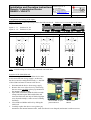
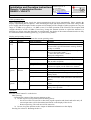
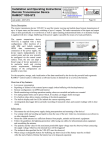
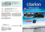
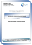
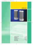
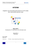
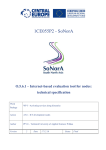
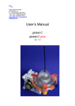
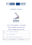
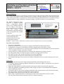
Installation and Operating Instructions
Remote Transmission Device
RAMOC® VD4-ST2
Innotas Produktions GmbH
Friedrich-Engels-Str. 46
D-15745 Wildau
+ 49 (3375) 529649 0
+ 49 (3375) 529649 24
Email: [email protected]
www.innotas-service.de
Last update - 28.07.2014
Page 1/8
Device Description:
The remote transmission device VD4-ST2 is used for remote viewing and mobile-based remote transmission of
up to 16 input states and for remote switching of up to 5 outputs. The radio transmission of the input and output
states is done periodically or event-driven as well as upon reaching predetermined limits or on demand. Energy
is supplied with low voltage. Buffering of the power supply is possible by means of a lead-acid battery.
The remote transmission device
VD4-ST2 is supplied together
with a configuration program
which is easy to handle. Thus, the
user can adapt a broad range of
device parameters to its particular
needs and existing system
requirements. Subsequent changes
of the configuration are possible
at any time.
For the reception, storage, and
visualization of the data
transferred by the device the
powerful and ergonomic
RAMOC®-control center is offered (as a software license or alternatively as a service) by Innotas.
Overview of key features:
• Low power consumption
• Reporting of failures of the external power supply (when buffering with backup-battery)
• Configuration by means of a MS Windows based PC-program (part of the delivery scope)
• Support for up to eight devices as a message recipient. Message texts can comfortably be generated in order
to use cell phones or pagers as message recipients.
• Analog values are recorded and pulses are counted beside monitoring switching operations
• For analog inputs limits can be preset which, if reached, can trigger alarm messages
• Five built-in relays allow remote switching of electrical equipment
• The built-in display and four LEDs indicate the current operating status
• An integrated data logger allows periodic recording of measured values and counter readings with its time
stamp
Safety notes:
• Disconnect the unit from power supply during transportation and mounting of the device!
• Use a damp cloth and washing up liquid to clean the case of the unit. Under no circumstances use abrasives
or other chemical cleaners!
• Mount the GSM antenna in a sufficient distance from people, animals and electronic equipment
• Follow the guidelines for lightning protection while laying out cables for telecommunication equipment
and assembling the antenna.
• The polarity and the value for the maximum permissible input voltage must be observed when connecting
the supply voltage. Otherwise the internal fuse will be triggered!
• The technical data specified for the VD4-ST2 must be observed.
• When using a rechargeable battery for buffering any short-circuit of the battery must be avoided!
After the end of battery lifetime the battery has to be disposed separately.
Installation and Operating Instructions
Remote Transmission Device
RAMOC® VD4-ST2
Innotas Produktions GmbH
Friedrich-Engels-Str. 46
D-15745 Wildau
+ 49 (3375) 529649 0
+ 49 (3375) 529649 24
Email: [email protected]
www.innotas-service.de
Last update - 28.07.2014
•
•
Page 2/8
Note that in GSM networks a caching of SMS takes place. Hence, the use of SMS for the transmission of
information may lead to delays or even the loss of messages in rare cases. In any case the delivery of the
SMS to its destination is carried out with a time delay depending on network load and other factors.
Further, a breakdown of the radio network or a consumed prepaid credit may prevent the transmission of
SMS. In some cases it may happen that the temporal order of SMS in the SMS Center is changed.
Therefore, the use of radio-based remote transmission systems, such as the VD4-ST2, is permitted only in
cases, where the above mentioned restrictions can not cause any harm to living beings or material goods.
Note that transmitting data (such as an SMS) via the GSM network, causes data transmission costs. Due to
malfunctions (such as an unforeseen periodic switching of an input) of the plant or respectively the process
which is monitored by the remote transmission device, a huge number of messages may be generated and
transmitted. Therefore it is possible to define (configure) the maximum allowed number of messages per
day. However note also, that a limitation of the messages sent per day may also cause a suppression of
required information.
Mounting:
The device will be mounted by snapping it onto a mounting rail TS35. In order to disassemble the device it has
to be pushed up or down against the spring and removed from the mounting rail.
VD4-ST2 survey:
Contrast control
for LCD
On / off switch
Power supply
connection
Rechargeable
battery connection
Power supply
fuse
DIP switches for input
configuration
Holder for GSM
SIM card
Button
T1
PC connection for
configuration
Installation and Operating Instructions
Remote Transmission Device
RAMOC® VD4-ST2
Innotas Produktions GmbH
Friedrich-Engels-Str. 46
D-15745 Wildau
+ 49 (3375) 529649 0
+ 49 (3375) 529649 24
Email: [email protected]
www.innotas-service.de
Last update - 28.07.2014
Page 3/8
Power supply connection:
The connection has to be made in a dead-voltage state (e.g. remove mains plug
from socket). The polarity and the specified voltage range (refer to technical
specification) have to be observed:
Labelling
Power Clamp
+
GND
Colour of
Meaning
Terminal Clamp
orange
Supply voltage plus
dark grey
Supply voltage minus (GND)
Note: All GND clamps are electrically connected with
each other.
On / off switch:
Using the on / off switch the device can be switched on
or off.
On / off switch
Fuse
Rechargeable battery
connection
Power supply
connection
Configuration of the device:
In order to configure of the remote transmission unit the device has to be connected to a serial port of a PC by
means of a configuration cable (if required, an USB to Serial adapter can be used). Then the device has to be
switched on. Afterwards, the configuration program VD4_Conf has to be started on the PC and using the button
“COM port settings” the serial port has to be selected to which the remote transmission unit is connected. All
further configuration settings are performed via the configuration program VD4_Conf. Finally, the established
serial connection has to be remove and the device has to be restarted by turning it off and on.
Rechargeable battery connection:
If required, a recharchable battery can be connected in order to back up the case of failure of the energy supply.
In any case the polarity of the battery must be observed and a short-circuit of the battery must be avoided:
Labelling
Akku Clamp
+BAT
GND
Colour of
Terminal Clamp
orange
dark grey
Meaning
Rechargeable battery connection plus
Rechargeable battery connection minus (GND)
Wiring of the outputs:
The outputs are implemented by bistable change-over contact relays. As shown on the
adjacent drawing, in the basic state "0", the two right-hand contacts are electrically
connected. By switching-over the output to state "1", the two left-hand contacts will be
connected. It can be configured whether the outputs will automatically be set to the basic
state "0" after switching on the remote transmission unit. Furthermore, it can also be
configured whether outputs which are switched to the state "1" will automatically be reset
to its initial state after a selected time (pulse generator).
Installation and Operating Instructions
Remote Transmission Device
RAMOC® VD4-ST2
Innotas Produktions GmbH
Friedrich-Engels-Str. 46
D-15745 Wildau
+ 49 (3375) 529649 0
+ 49 (3375) 529649 24
Email: [email protected]
www.innotas-service.de
Last update - 28.07.2014
Page 4/8
Configuration and wiring of the inputs:
Before connecting sensors and using contacts the DIP switches S1 .. S4 have to be set according to the input
requirements:
Inputs 1 .. 8: Switches S1, S2
Inputs 9 .. 16: Switches S3, S4
Connecting the cables and setting the DIP switches S1 .. S4 for various input options
0 .. 10 V Sensor
4 .. 20 mA - Sensor
Digital input, Counter input
Note: All GND clamps are electrically connected with each other.
Insertion of the GSM SIM card:
While inserting the GSM SIM card the device must
be disconnected from energy supply! At this time
the device must be configured basically, i.e. the PIN
of the GSM-card must be known to the device:
1. Disconnected the device from energy supply
2. Remove the cover of the device by unscrewing
the two screws carefully (please pay attention to
the internal antenna cable)
3. Open SIM card holder (Push the slider towards
clamps and fold up the SIM card holder) and
insert the SIM-card (the chip of SIM card points
away from the clamps, corner recess is finally
inserted).
Observe recess in
SIM card holder. To open it
SIM card.
push the slide down.
4. Close SIM card holder and lock by sliding the
slide back.
5. Carefully replace the device cover (please pay
attention to the internal antenna cable, make sure that it is not clamped) and mount it with two screws.
Installation and Operating Instructions
Remote Transmission Device
RAMOC® VD4-ST2
Last update - 28.07.2014
Innotas Produktions GmbH
Friedrich-Engels-Str. 46
D-15745 Wildau
+ 49 (3375) 529649 0
+ 49 (3375) 529649 24
Email: [email protected]
www.innotas-service.de
Page 5/8
Initial operation phase:
After connecting the power supply the remote transmission device boots automatically. Please monitor the
display output during the boot process. After initializing the input and output states as well as the voltage of the
power supply and the strength of radio reception will be displayed. The strength of radio reception can vary in a
range of -51 dBm (very good) to -113 dBm (worst). For stable operation of the VD4-ST2, the reception field
strength should be at least -85 dBm. If necessary, change the antenna location or replace the antenna by a
different type. Please note that depending on configuration, the display of the remote transmission device may
be switched off while on battery power (e.g. in "power saving mode").
Display and operating elements:
Four LEDs provide information about the current operating status:
LED
Meaning
Status of lighting
Meaning
L1-ERR Error indicator dark
No error – normal operation status
(red)
No radio transmission (SIM card not inserted,
flashes
incorrect PIN, specified maximum message number
per day is reached)
lights permanently
… and at the same time L3 lights permanently:
device in boot loader mode
… and at the same time L3 flashes:
destroyed configuration
L2-GSM GSM-status
dark
GSM modem off or in “Power Saving Mode”
(yellow)
No
radio network (SIM card not inserted, incorrect
flashes
PIN, no radio reception)
flashes briefly every 3 s Normal operation, registered in the GSM network
lights permanently
Radio transmission of the content of the data logger
or Firmware update via the GSM voice channel
L3-CPU Operation
dark
Device switched off
(green)
indicator
Normal operation, CPU operates
flashes
leuchtet alle 4 s kurz auf CPU operates in power saving mode (rechargeable
battery mode)
lights permanently
… and at the same time L1 lights permanently:
CPU in boot loader-mode (in order to run firmware
update)
L4-+Us Sensor supply
dark
Sensors are not powered, no measurement of analog
(green)
values
lights
Sensors are supplied with energy, measurement of
analog values possible
Operation:
Press the yellow button T1 on the device:
Short pressing:
- Resetting the counter of the message attempts per day
a) In case of power saving mode (when on battery power):
- the device will be activated for a short time (regular operation and deactivated radio unit), all
current input states will be determined and shown on the display of the device
- Renewed pressing: The radio unit will be turned on
b) In case of regular operation mode: Output of additional information on the display
Pressing for at least 6s: Resetting the device.
Installation and Operating Instructions
Remote Transmission Device
RAMOC® VD4-ST2
Innotas Produktions GmbH
Friedrich-Engels-Str. 46
D-15745 Wildau
+ 49 (3375) 529649 0
+ 49 (3375) 529649 24
Email: [email protected]
www.innotas-service.de
Last update - 28.07.2014
Page 6/8
Maintenance:
The remote transmission unit itself is maintenance-free. If
necessary, the contrast of the display can be adjusted by means of a
Phillips screwdriver in size PH0.
Hole for contrast
adjustment
Repair:
Repairs may only be carried out by the manufacturer. The device
must be replaced, if the remote transmission device is defective.
The replacement of the fuse (which triggers on surge voltage of the power supply) is permitted only by a fuse
with identical specification according to the supplied technical specification of the device!
Troubleshooting:
No response (no display outputs, no lighting of the LED L3)
- Check the fuse of the device
- Check the polarity of the power supply (plus / minus correct?)
- Power switch is ON?
No display outputs, lighting of the LED L3 every 4s:
Battery operation mode, the device is in power saving mode (the display is switched off in order to
secure a long running time of the device), short term display output can be activated by pressing button T1
Bad or fluctuating display contrast
- Ambient temperature at the boundaries of acceptable values?
- Voltage of the power supply < 4 V?
- Contrast adjustment refer to item Maintenance:
LED L1 lights permanently
- Supply voltage less than 5.0 V and battery voltage < 10,8V
- Failed to initialize the radio unit Observe display outputs at power on or press T1 button for renewed
display
o Missing SIM card
o Incorrect SIM-PIN revise configuration
o SIM card locked after having have entered 3 wrong PIN codes in a row. Unlock SIM card by
means of a mobile phone with correct PIN
Obsolete display or no display of the measured values of sensors
- Press button T1 in order to determine and display the current value
Device can not be reset by briefly interrupting the power supply or switching the device off and on
- The power supply must be interrupted until the display and LED L3 permanently remain turned off.
- Alternatively press button T1 for at least 6s
Installation and Operating Instructions
Remote Transmission Device
RAMOC® VD4-ST2
Innotas Produktions GmbH
Friedrich-Engels-Str. 46
D-15745 Wildau
+ 49 (3375) 529649 0
+ 49 (3375) 529649 24
Email: [email protected]
www.innotas-service.de
Last update - 28.07.2014
Specifications:
Type of the device:
Page 7/8
Remote Transmission Device RAMOC® VD4-ST2
Dimensions:
(W x H x D) 212 x 105 x 95 mm, plus fittings and antenna
Mounting:
On mounting rail TS35
Inputs:
16 universal inputs, configurable as
- Analogue-Input
o Resolution 8 Bit
o prepared for sensors with:
4 .. 20 mA - Output (input resistance 125 ohms)
0 .. 20 mA - Output (input resistance 125 ohms)
0 .. 10 V - Output (input resistance 40 kohms)
o basic accuracy at 25 ° C in measuring range
0 .. 20 mA: 0,7 %
0 .. 10 V: 0,4 %
- Counter-Input (digital)
o for the connection of potential-free contacts
o puls duration > 100 ms
o contact load < 4mA (pulsed)
- Digital-Input
o for the connection of potential-free contacts
o contact load < 4mA (pulsed)
Clamping range: 0,08 .. 2,5 mm²
Sensor power supply:
electronically controlled voltage generation for sensors,
+Us= 17,5 V DC, maximum total current of all sensors: 0,32 A
(maximum total current is dependent on the supply voltage, at battery power
maximum total current of all sensors: 0.25 A)
Outputs:
5 switching outputs, Type: bistable change-over contact relay, potential-free,
load-bearing capacity 30 V DC, 1A with resistive loads, automatic reset is
possible (pulse generator)
Radio:
built-in GSM modem, quad band, SIM card required (3V or 1.8V)
Antenna connector:
FME-plug
Power supply:
Supply voltage UV
-
on battery backup
o UV = 15 V DC
- no battery backup
o Total current of all sensors >= 0,15 A: UV = 11.. 27 V DC
o Total current of all sensors < 0,15 A: UV = 6.. 27 V DC
Clamping range: 0,08 .. 2,5 mm²
Current consumption:
Current consumption Ityp is dependent on
- Total current of all sensors
- Level of supply voltage UV
- Charging status of backup battery
- GSM-status (increased power consumption on message transmission)
Installation and Operating Instructions
Remote Transmission Device
RAMOC® VD4-ST2
Innotas Produktions GmbH
Friedrich-Engels-Str. 46
D-15745 Wildau
+ 49 (3375) 529649 0
+ 49 (3375) 529649 24
Email: [email protected]
www.innotas-service.de
Last update - 28.07.2014
Page 8/8
Normal operation mode:
- on battery backup UV = 15 V DC
o total current of all sensors 0,32 A: Ityp = 0,8 A
o total current of all sensors 0,15 A: Ityp = 0,5 A
o total current of all sensors 0,05 A: Ityp = 0,35 A
o no sensor power supply: Ityp = 0,2 A
- no battery backup UV = 24 V DC
o total current of all sensors 0,32 A: Ityp = 0,4 A
o total current of all sensors 0,15 A: Ityp = 0,25 A
o total current of all sensors 0,05 A: Ityp = 0,1 A
o no sensor power supply: Ityp = 23 mA
- no battery backup UV = 12 V DC
o total current of all sensors 0,32 A: Ityp = 0,75 A
o total current of all sensors 0,15 A: Ityp = 0,35 A
o total current of all sensors 0,05 A: Ityp = 0,15 A
o no sensor power supply: Ityp = 23 mA
- no battery backup UV = 6 V DC
o total current of all sensors 0,15 A: Ityp = 0,8 A
o total current of all sensors 0,05 A: Ityp = 0,3 A
o total current of all sensors: Ityp = 23 mA
Power saving mode (battery power supply only): Ityp = 0,4 mA
Recommended dimensioning
of energy supply:
-
on battery backup: 15 V DC 12 W
no battery backup: 12 .. 24 V DC 10 W
Battery connection:
for 12V lead acid battery, charge current approximately 0.1 .. 0.2 A,
recommended capacity 1.3 Ah
Temperature range:
-20 °C .. +60 °C
Internal melting fuse:
Subminiature fuse 1.0 A, slow, type TR5
Replacing the fuse is permitted only by a fuse with identical specification!
A triggering of the fuse indicates a surge of the energy supply. The fuse can
be ordered from the Innotas Produktions GmbH.
Manufacturer:
Innotas Produktions GmbH
Friedrich-Engels-Str. 46
D-15745 Wildau, Germany
Scope of delivery:
Remote transmission device RAMOC® VD4-ST2
Mini-antenna
Installation and Operating Instructions
Configuration program VD4_Conf, configuration instructions
Optional accessories:
External antenna
Power supply unit 230 V
Buffer battery for top hat rail mounting
Control center software and hardware
GSM SIM-card
USB to Serial adapter