1
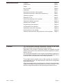
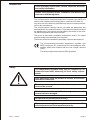
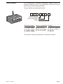
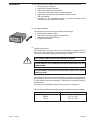
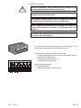
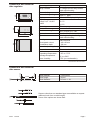
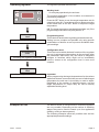
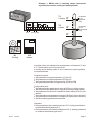
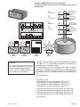
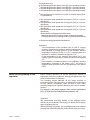
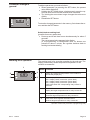
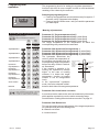
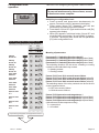
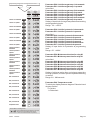
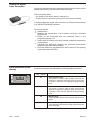
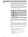
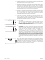
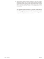
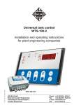
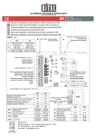
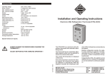
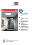
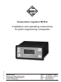
WELBA
Temperature regulator MPR-A
101658 - © by WELBA - 01/04/09
Installation and operating instructions
for plant engineering companies
WELBA GmbH
Electronic Control Engineering
Gewerbepark Siebenmorgen 6
D-53547 Breitscheid
Phone:
Fax:
E-mail:
Net:
+49 (0)2638 / 9320-0
+49 (0)2638 / 9320-20
[email protected]
www.welba.de
Inhaltsverzeichnis
Function . . . . . . . . . . . . . . . . . . . . . . . . . . . . . . . . . . . . . . . . . Page 3
Intended use . . . . . . . . . . . . . . . . . . . . . . . . . . . . . . . . . . . . . Page 3
Safety . . . . . . . . . . . . . . . . . . . . . . . . . . . . . . . . . . . . . . . . . . . Page 3
Key to models. . . . . . . . . . . . . . . . . . . . . . . . . . . . . . . . . . . . . Page 4
Installation . . . . . . . . . . . . . . . . . . . . . . . . . . . . . . . . . . . . . . . Page 5
Dimensions and techn. data regulator . . . . . . . . . . . . . . . . . . Page 7
Dimensions and techn. data sensor (accessory) . . . . . . . . . . Page 7
Operating regulator . . . . . . . . . . . . . . . . . . . . . . . . . . . . . . . . Page 8
Examples of use. . . . . . . . . . . . . . . . . . . . . . . . . . . . . . . . . . . Page 8
Notes for programing of the regulator . . . . . . . . . . . . . . . . . . Page 11
Parameter settings in general . . . . . . . . . . . . . . . . . . . . . . . . Page 12
Working level operation . . . . . . . . . . . . . . . . . . . . . . . . . . . . . Page 12
Programming level operation . . . . . . . . . . . . . . . . . . . . . . . . . Page 13
Configuration level operation . . . . . . . . . . . . . . . . . . . . . . . . . Page 14
Setting the actual value correction . . . . . . . . . . . . . . . . . . . . . Page 16
Fault indication on the display . . . . . . . . . . . . . . . . . . . . . . . . Page 16
General measures when using electronic control systems . . Page 17
Function
The microprocessor-controlled temperature regulator of the series
MPR-A are used to control heating and cooling processes.
Depending on the number of switching stages, the regulator unit has
between one and four relay contacts to control the compressor, heaters,
alarms, fans, etc.
The measured temperature of the medium is permanently displayed. If
this temperature deviates from the selected target temperature by the
hysteresis value, the appropriate relay contact is activated.
The operation and the default values of the regulator are subdivide in
three parameter levels. The assessment for each level is configurable
by the assemblyman.
At the first operating level the working level a button can be pressed to
display and change the target temperature set for relay contact K1. (The
alter of the target temperature for the operating level can be looked.)
MPR-A
28/08/08
Page 2
Intended use
These operating instructions contain important technical
and safety information.
Please read carefully before installation and before any
work on or with the regulator.
The microprocessor-controlled temperature regulator type MPR-A is
used to control heating and cooling systems, alarm devices, fans, etc.
Any other use of the device is permitted only with prior written permission from the manufacturer.
The microprocessor controller can be used after the parameters has
been adjusted if it is used the first time. To get start the controller without
the adjustments is not igneous and can destroy the facility or the medium which temperature has to be controlled.
The device is fitted with a resistance temperature sensor. The output
ports are designed as potential-free relay ports.
The device must not be installed in potentially explosive atmospheres.
The microprocessor-controlled temperature regulator type
MPR-A meets the EC requirements for electromagnetic compatibility (EMC) and complies with the "low voltage" directive
(LVD).
The safety components meet the VDE regulations.
Safety
The temperature regulator may only be installed by an
authorised specialist, observing all local safety requirements.
Only specialists must be allowed to access the environment when connected.
The temperature regulator contains live components and
must not be opened.
The device must not be used if the housing or the connection terminals are damaged.
No liquids must penetrate the housing.
The temperature regulator may be exported to the USA
with the permission of the manufacturer only.
MPR-A
28/08/08
Page 3
Key to models
The microprocessor controlled temperature regulator MPR-A is
available in different versions. The type definition of the device can you
find on the top of the housing (see picture).
The type definition is configured as follows:
M P R A -
-
-
Switching stages
Sensor preparation
Voltage
Switching stages
Sensor preparation Voltage
1
2
3
4
KT KTY 81-210
P2 PT100 (2 leads)
P3 PT100 (3leads)
1 switch. stage
2 switch. stages
3 switch. stages
4 switch. stages
A
C
D
F
230V AC, 50/60 Hz
24V AC, 50/60 Hz
24V DC
24V UC
This manual contains all specifications to operate all variants.
MPR-A
01/04/09
Page 4
Installation
1
2
3
°C
SET
a. It is essential not to install the device under the following conditions:
! severe jolting or vibration
! permanent contact with water
! relative humidity of more than 90%
! sharply fluctuating temperatures (condensation)
! aggressive atmospheres (ammonia or sulphur fumes).
Risk of oxidation.
! operation in the immediate vicinity of radio transmitters with
increased levels of spurious radiation.
b. Housing installation
The housing is mounted using two lateral screw fittings.
! Fit the rubber seal as shown
! Place the housing throught thr front opening.
! Attach the lateral screw fittings.
! Thighten the screws.
c. Installing the sensor
The temperature controller has been configured for a specific kind of
sensors by the manufacturer (see type key). Notice that the controller
can only work well if the right type of the sensor is fitted.
The sensor cable must not be chafed or kinked.
There must be no substantial mechanical pressure on the
sensor tube.
Do not place the sensor and the power cable in the same
cable conduit.
After finishing the electrical connections the regulator must be adjust in
the parameter “Sensor correction” [C91] that the measured temperature
is equal with the value on the display. Therefore it must used a reference
thermometer.
See the section "Setting the actual value correction" on page 16.
Observe the permitted temperature range to which the sensor is suited:
Sensor cable
PVC (standard)
Silicon
Teflon
MPR-A
28/08/08
Temperature range
-30° to + 70 °
-50° to +150°
-100° to +205°
Page 5
d. Electrical connection
Before connecting, ensure that the mains voltage is the
same as indicated on the device's type plate.
Incorrect electrical connection can cause damage to the
regulator and to the equipment.
The mains voltage should not be switched on until all
components including the sensor are connected.
When connecting appliances (or loading the relay contacts) with currents of >10A AC1, it is essential to fit contactors.
Downstream contactors must be fitted with an RC protection circuit. (see also page 17).
You will find the correct circuit diagram for your regulator on the
back of the housing, above the connection terminals..
* = depending on the number of switching stages
KTY10-6
K1
K2*
The electrical connection procedure is as follows:
! Connect heating and cooling systems in accordance with the
appropriate circuit diagram.
! Connect alarm devices, fans, etc.
! Connect mains supply leads.
K3*
PT100
A1 A2
1 2 3 4 5 6 7 8 9 10 11 12 13 14 15
Sensor
MPR-A
Observe the following tips:
! Use cable bushes.
! Make sure that cables cannot chafe.
Operating voltage
28/08/08
Page 6
Dimensions and technical
data regulator
Operating voltage
Relay contacts
48
Max. switching current
Max. switching voltage
Display
Display range
- range -9,9 .. 99,9°C
- other
Control type
Measurement range
Usable sensor types
Hysteresis
Operation
42
96
77
88
8
90
76
Housing
- front-panel cut-out
- installation depth
Protection (housing front)
Connection
Ambient temperature
- operating temperature
- storage temperature
- max. humidity
See key to models
1 voltage-free two-way-contact
each switch setting
10 A AC1 each
250 V ~ each
13 mm LED display, 3 digits
0.1°C
1.0°C
Two-step regulator
KTY 81-210 or PT 100
0.1 K to 99.9 K freely adjustable
Heating/cooling interchangeable
each switch setting
NEG 48/96 M
- 42 x 90 mm
- 88 mm
IP 64
Screw terminals
-20° to +70°C
0° to +50°C
75% (no condensation)
Technical facts with reservation.
40 mm
6,0 mm
6,1 mm
Dimensions and technical
data sensor
Bush material
Bush length
Bush diameter
1.4301(V2A)
40 mm
6.0 mm +/- 0.1
Sensors other than our standard type are available on request
(different bush from or cable length).
Some of the options are shown here.
MPR-A
28/08/08
Page 7
Operating regulator
The regulator operates at three levels:
°C
1
2
3
4
Working level:
.…for everyday operation by the end user.
The present temperature of the medium as measured is
permanently displayed.
SET
Press the SET button to see the target temperature set for
output port relay K1. Press the up-arrow or down-arrow key
as the same time as the SET button to adjust the target
temperature.
NB: The target temperature can be adjusted here only if the
programming level button lock [C99] is set to “0”
Working
level
for every day operation
Programming
level
for setting the regulator parameters
Programming level:
This is the level at which the regulatory parameters are set.
Setting is more complex and possible only using specific
combinations of buttons so as to prevent accidental changes to settings.
Configuration level:
This is the level at which the basic functions of the regulator
are set. As subsequent interventions by the end user (after
the parameters have been set) can result in dangerous
changes to functions which might not be immediately
obvious, access to the configuration level is even more
complex.
Configuration
level
for setting the basic functions
Important:
When programming the target temperatures for the various
appliances that are connected, take account of which target
temperature the end user is most likely to need to adjust.
Regardless of the number of switching stages, only the
target temperature for output relay K1 can be directly
adjusted at working level.
Examples of use
The MPR-A series of microprocessor controlled regulators
are very versatile: Depending on the number of switching
stages, they can be used to control up to four appliances
(heating, cooling or alarm systems).
The following examples show two possible uses and the
appropriate parameter settings.
MPR-A
28/08/08
Page 8
Example 1: MPR-A with 2 switching stages (three-point
regulation) to control a cooling and heating system
1
2
°C
SET
K1
KTY10-6
1 2 3 4 5 6 7 8 9 10 11 12 13 14 15
K1
Cooling
Operating voltage
9°
T2
Heater
4°
Hysteresis
for T1
(upwards
only)
K2
A1 A2
Sensor
T1
Cooling
Hysteresis
for T2
(downwards
only)
0°
K2
Heater
A medium has to be maintained at a temperature of between 9°C and
4°C. The deviation must not exceed 0.5K.
A cooling and a heating system is to be used (three point regulation).
Proceed as fallows:
Programming level:
! Set parameter for target-temperature 1 [C1] to 9°C
! Set parameter for target-temperature 2 [C2] to 4°C
! Set hysteresis parameter for target-temp. 1 [C20] to 0.5K
! Set hysteresis parameter for target-temp. 2 [C21] to 0.5K
Configuration level:
! Set switch direction parameter for relay K1 [P1] to 1 (cooling contact)
! Set switch direction parameter for relay K1 [P2] to 0 (heating contact)
! Set parameters for function K1 and K2 for sensor failure [P10+P11] as
desired
! Set hysteresis mode parameter for target 1 [P15] to 1 [mono-direction]
! Set hysteresis mode parameter for target 2 [P16] to 2 [mono-direction]
! Set the remaining parameters as desired
Operation
! If the temperature of the medium rises to 9.5°C, cooling is switched on,
and then switched off again at 9°C
! If the temperature of the medium falls below 3,5°C, heating is switched
on, and then switched off again at 4°C
MPR-A
28/08/08
Page 9
Example 2: MPR-A with four switching stages
to control of two cooling systems, a heating system and a
alarm system
1
2
°C
13°
T2
Cooling 1
10°
Hysteresis
for T2 / 0,8K
(upwards
only)
T1
Heater
6°
T4
Alarm
Hysteresis
for T1 / 0,6K
(downwards
only)
3°
Hysteresis
for T4 / 0,1K
(downwards
only)
SET
K1
KTY10-6
K2
A1 A2
1 2 3 4 5 6 7 8 9 10 11 12 13 14 15
Operating voltage
Sensor
K3
Hysteresis
for T3 / 0,5K
(upwards
only)
T3
Cooling 2
0°
K4
16 1718 19 20 21 22 23 24 25 26 27 28 29 30
K3
Cooling 2
K2
Cooling 1
Caution:
The device is programmed so that
the target temperature for heating
can be changed at working level.
This is why the heating system is
connected to relay contact K1.
K1
Heater
K4
Alarm
A medium is to be maintained at a temperature of between
13°C and 6°C. The permissible temperature deviations are
controlled by the hysteresis settings.
The temperature is to be controlled by two cooling systems,
which will be switched on one depending on the temperature of
the medium. A heating system will prevent the temperature
from falling below 6°C. An additional alarm is to be activated at
3°C
Proceed as follows:
Programming level:
! Set parameter for target temperature 1 [C1] to 6°C
! Set parameter for target temperature 2 [C2] to 10°C
! Set parameter for target temperature 3 [C3] to 13°C
! Set parameter for target temperature 4 [C4] to 3°C
!
!
!
!
Set hysteresis parameter for target-temp. 1 [C20] to 0.6K
Set hysteresis parameter for target-temp. 2 [C21] to 0.8K
Set hysteresis parameter for target-temp. 3 [C22] to 0.5K
Set hysteresis parameter for target-temp. 4 [C23] to 0.1K
See next page.
MPR-A
28/08/08
Page 10
Configuration level
! Set switching direction param. for K1 [P1] to 0 (heating contact)
! Set switching direction param. for K2 [P2] to 1 (cooling contact)
! Set switching direction param. for K3 [P3] to 1 (cooling contact)
! Set switching direction param. for K4 [P4] to 0 (heating contact)
! Set parameters for functions K1 to K4 for sensor failure [P10P13] as desired
! Set hysteresis mode parameter for target 1 [P15] to 1 (monodirectional)
! Set hysteresis mode parameter for target 2 [P16] to 1 (monodirectional)
! Set hysteresis mode parameter for target 3 [P17] to 1 (monodirectional)
! Set hysteresis mode parameter for target 4 [P18] to 1 (monodirectional)
Mono directional hysteresis mode means:
- switching direction for cooling contact: hysteresis upwards
- switching direction for heating contact: hysteresis downwards
! Set the remaining parameters as desired
Operation:
" If the temperature of the medium rises to 10.8°C, cooling
system 1 is switched on, and then switched off again at 10°C.
" If the capacity of cooling system 1 is not sufficient, and the
temperature continues to rise to 13,5°C, cooling system 2 is
switched on, and then switched off again at 13°C.
" If the temperature of the medium falls below 5.4°C, the
heating system is switched on, and then switched off again at
6°C.
" If the capacity of heating system is not sufficient, and the
temperature continues to fall below 2,9°C, the alarm is
triggered and continues until the temperature rises above
3,0°C.
Notes for programing of the
regulator
Before starting operation, all pre-set parameters should be
adjusted to suit local conditions. Wrongly set parameters can
have a serious effect on functions.
The following pages educible all the steps involved in
programming the various models. In following the instructions
for the various parameters, take account of now many
switching stages your regulator has (see also “key to models”
section)
For example, a two-stage regulator does not have parameters
[C3] + [C4] for the second and third temperatures, etc."
Important:
We recommend recording details of the settings before
delivery to your customer. In this way you will be able to supply
spare regulators pre-set.
When replacing a regulator, the only adjustment to be made at
the end user's premises will then be the actual value correction.
MPR-A
28/08/08
Page 11
Parameter settings in
general
1
2
3
4
To adjust a parameter, proceed as follows:
! Select parameter (on pressing the SET button, the present
value will be displayed).
! Holding the SET button down, simultaneously press the uparrow or down-arrow until the desired value is reached.
! Tip: Holding the arrow down longer changes the value more
quickly.
! Release the SET button.
°C
15. 8
To store the changed parameter in the memory, first release the arrow, and then the SET button.
SET
Switch back to working level
(possible from every parameter)
! Press up-arrow and down arrow simultaneously for about 5
seconds.
The current actual value appears in the display.
(If, at programming or configuration level, no buttons are
presses for about 1 minute, the regulator switches back to
working level automatically.)
Working level operation
The working level is for everyday operation by the end user. The
display permanently shows the present temperature of the
medium as measured.
1
2
1
2
3
4
3
SET
15. 8
Button Function
°C
4
5
1
Display (the measured temperature of the medium is
permanently displayed.)
2
LED - Display "Relay contact K1"
LED - Display "Relay contact K2" (when fitted)
LED - Display "Relay contact K3" (when fitted)
LED - Display "Relay contact K3" (when fitted)
These show when the corresponding relay contact is
activated.
3
Press SET button:
Display the target temperature set for relay contact K1
4*
Press up-arrow together with SET button:
Increases target temperature for relay contact K1
5*
Press down-arrow together with SET button:
Reduces target temperature for relay contact K1
* (See also “button lock” parameter at programming level)
MPR-A
28/08/08
Page 12
Programing level
operation
1
2
3
4
15. 8
The programming level is for setting the regulator parameters.
Access to this level is more complex in order to avoid accidental
resetting of the values by the end user.
Switching to programing level:
! Press up-arrow and down-arrow simultaneously for approx. 5
seconds, until [C1] appears in the display.
! Press up-arrow or down arrow until you reach the parameter
you want adjust.
°C
SET
Meaning of parameters
Operating diagram programming level
Switch to programming level =
Press simultaneously for approx. 5
Show
setting
Change
setting
Press
SET
button
Press SET button
and or
simultaneously
or
Target temperature 1
C1
Target temperature 2
C2
Target temperature 3
C3
Target temperature 4
C4
Hysteresis for
target temperature 1
C20
Hysteresis for
target temperature 2
C21
Hysteresis for
target temperature 3
C22
Hysteresis for
target temperature 4
C23
Sensor correction
C91
Button lock
C99
SET
or
SET
Switch back to working level =
Press simultaneously for approx. 5 seconds
(Switches back automatically after approx.
1 minute if no further buttons are pressed).
Parameter C1: Target temperature for K1
Parameter C2: Target temperature for K2 (when fitted)
Parameter C3: Target temperature for K3 (when fitted)
Parameter C4: Target temperature for K4 (when fitted)
The target temperature is the temperature at which the
corresponding relay contact is to be activated.
Parameter C20: Hysteresis for target-temp. 1
Parameter C21: Hysteresis for target-temp. 2 (when fitted)
Parameter C22: Hysteresis for target-temp. 3 (when fitted)
Parameter C23: Hysteresis for target-temp. 4 (when fitted)
The hysteresis determines the
value by which the temperature of
the medium may deviate from the Target temperature
Hysteresis for
corresponding target temperature “cooling
T2
contact”
T2 higher
before the relay contact is activat- Target temperature
“heating
ed. See sketch.
contact”
T1
Hysteresis for
T1 lower
If the contact in question is for
cooling, the hysteresis is always
0°
higher. In the case of heating
contacts it is below the target
temperature. (cooling or heating
contact is set at configuration
level).
In the “symmetrical” hysteresis
mode, the value selected is distributed on both sides of the target temperatures.
Parameter C91: Actual value correction
A correction can be made to the value as measured by the sensor,
which applies cumulatively over the entire measuring range.
See the section “Setting the actual value correction” on page 16.
Parameter C99: Button lock
This can be used to prevent adjustment of the target temperature
for outlet port relay K1 in the working level .
0 = Buttons not locked
1 = buttons locked
MPR-A
28/08/08
Page 13
Configuration level
operation
1
2
3
4
15. 8
This level is for configuring the regulator's basic functions.
To prevent interference by the end user, access
is made even more complex.
°C
Switching to configuration level:
! Press up-arrow and down-arrow simultaneously for
approx. 5 seconds, until [C1] appears in the display.
! Press button "Arrow UP" repeatedly until the last
parameter [C99] at working level is reached.
! Press button "Arrow UP" again and hold down until [Pb]
appears in the display.
! When [Pb] appears, hold down button "Arrow UP" and
simultaneously press button "Arrow DOWN" for approx.
3 seconds. The display then shows the first parameter
[P1] in the configuration level.
SET
Operating diagram configuration level
Switching to configuration level: see description
Show
setting
Press
SET
button
Change
setting
Press SET button
and or
simultaneously
Meaning of parameters
or
Switching
direction K1
P1
Switching
direction K2
P2
Switching
direction K3
P3
Switching
direction K4
P4
Sensor failure
function K1
P10
Sensor failure
function K2
P11
Sensor failure
function K3
P12
Sensor failure
function K4
P13
Hysteresis mode
for 1
P15
Hysteresis mode
for 2
P16
Hysteresis mode
for 3
P17
Hysteresis mode
for 4
P18
SET
Parameter P1: Switching direction relay K1
Parameter P2: Switching direction relay K2 (when fitted)
Parameter P3: Switching direction relay K3 (when fitted)
Parameter P4: Switching direction relay K4 (when fitted)
The switching direction can be set as a heating or cooling
contact for each individual relay contact.
0 = Heating contact
1 = Cooling contact
Param. P10: Funct. K1 in event of sensor failure
Param. P11: Funct. K2 in event of sensor failure (when fit)
Param. P12: Funct. K3 in event of sensor failure (when fit)
Param. P13: Funct. K4 in event of sensor failure (when fit)
The switching status of the relay contacts can be set for the
event of a sensor failure.
0 = OFF in the event of failure
1 = ON in the event of failure
or
SET
Param. P15: Hysteresis mode target temp. 1
Param. P16: Hysteresis mode target temp. 2 (when fitted)
Param. P17: Hysteresis mode target temp. 3 (when fitted)
Param. P18: Hysteresis mode target temp. 4 (when fitted)
(with reference to the compressor relay)
0 = symmetrical
1 = one-sided
Operating diagram configuration level
MPR-A
28/08/08
Page 14
Operating diagram configuration level
Show
setting
Press
SET
button
Change
setting
Press SET button
and or
simultaneously
or
Limit for T1 downwards P20
Limit for T1 upwards
SET
P21
Limit for T2 downwards P22
Limit for T2 upwards
when fitted
Parameter P22: Limit for target temp. 2 downwards
Parameter P23: Limit for target temp. 2 upwards
Parameter P24: Limit for target temp. 3 downwards
Parameter P25: Limit for target temp. 3 upwards
Parameter P26: Limit for target temp. 4 downwards
Parameter P27: Limit for target temp. 4 upwards
Setting of input limits for target temperatures at working
and programming levels.
Range: -50 .. +400°C
Parameter P30: Limit for hysteresis 1 downwards
Parameter P31: Limit for hysteresis 1 upwards
P23
Limit for T3 downwards P24
Limit for T3 upwards
Parameter P20: Limit for target temp. 1 downwards
Parameter P21: Limit for target temp. 1 upwards
when fitted
Parameter P32: Limit for hysteresis 2 downwards
Parameter P33: Limit for hysteresis 2 upwards
Parameter P34: Limit for hysteresis 3 downwards
Parameter P35: Limit for hysteresis 3 upwards
Parameter P36: Limit for hysteresis 4 downwards
Parameter P37: Limit for hysteresis 4 upwards
Setting of input limits for hysteresis at programming
level.
Range: -50 .. +400 K
P25
Limit for T4 downwards P26
Limit for T4 upwards
P27
Limit for hysteresis 1
downwards
P30
Limit for hysteresis 1
upwards
P31
Limit for hysteresis 2
downwards
P32
Parameter P50: Minimum action time for relay K1
Parameter P51: Minimum pause time for relay K1
Limit for hysteresis 2
upwards
P33
Limit for hysteresis 3
downwards
P34
Limit for hysteresis 3
upwards
P35
Limit for hysteresis 4
downwards
P36
Limit for hysteresis 4
upwards
P37
Min. action time K1
P50
when fitted
Parameter P52: Minimum action time for relay K2
Parameter P53: Minimum pause time for relay K2
Parameter P54: Minimum action time for relay K3
Parameter P55: Minimum pause time for relay K3
Parameter P56: Minimum action time for relay K4
Parameter P57: Minimum pause time for relay K4
Setting of minimum action time or minimum pause time
for relay contacts, in order to prevent repeated switching
on and off.
Range: 0.0 .. 999 seconds
Min. pause time K1
P51
Min. action time K2
P52
Min. pause time K2
P53
Min. action time K3
P54
Min. pause time K3
P55
Min. action time K4
P56
Min. pause time K4
P57
Temperature scale
P99
Parameter P99: Temperature scale
To switch the display between degrees Fahrenheit and
degrees Celsius.
0 = Celsius
1 = Fahrenheit
or
SET
Switch back to working level =
Press simultaneously for approx. 5 seconds
(Switches back automatically after approx.
1 minute if no further buttons are pressed).
MPR-A
28/08/08
Page 15
Setting the actual
value correction
A correction can be made to the value as measured by the sensor, which
applies cumulatively over the entire measuring range.
This is necessary when:
- the length of the sensor cable is changed, or
- a faulty sensor is replaced, giving rise to an incorrect reading.
In order to adjust the actual value correction, a reference thermometer
(e.g. WELBA THM-2000) is needed.
Proceed as follows:
! Install sensor.
! Measure the temperature of the medium using the reference
thermometer.
! Switch on the thermostat and set parameter [C91] in the
programming level to "0".
! Switch back to working level and read the measured temperature
on the display.
! Calculate the difference between the reference thermometer
temperature and the display reading.
! Store the difference (pay attention to plus or minus) in the working
level under parameter [C91].
Fault indication on the
display
1
2
3
4
15. 8
°C
Faults in the regulator are indicated by a flashing display as follows:
LED - Display
F1
Sensor short circuit:
The sensor or sensor cable is faulty and must be
replaced or repaired. Parameter [C91] "Actual value
correction" must then be adjusted at programming
level.
F2
Broken sensor:
The sensor or sensor cable is faulty and must be
replaced or repaired. Parameter [C91] "Actual value
correction" must then be adjusted at programming
level.
F3
Memory fault:
Faulty regulator! Remove the regulator and send it for
repair.
FFF
Measurement range exceeded:
The maximum measurement range of the sensor has
been exceeded.
SET
MPR-A
28/08/08
Fault
Page 16
General measures when
using electronic control
systems
So that even complicated regulatory tasks can be presented to the user
in a manner which is clear and simple and ensures high measurement
accuracy, today's electronic control systems make increasing use of
microprocessors. However, the benefits of these systems are countered
by the disadvantage that increased measurement accuracy is accompanied by sensitivity to interference. In order to minimise the effect
which interference may have on the regulator, the user also must take
account of a number of points when installing a new regulator.
Assistance here is provided by standard DIN VDE 0843 on the electromagnetic compatibility (EMC) of measurement, control and regulatory
devices in industrial process technology. The following table shows, for
example, the maximum interference levels to which, according to the
standard, an appliance may be exposed.
Degree of
severity
Environment
class
Test voltage
Power supply
Test voltage
Signal/control line
1
well-protected
environment
0.5 kV
0.25 kV
2
protected
environment
1.0 kV
0.5 kV
3
typical industrial
environment
2.0 kV
1.0 kV
4
Industrial environment with very high
interference level
4.0 kV
2.0 kV
As the values given in the table are maximum values, operational values
should remain well below them. However, in practice this is possible only
with difficulty, as even a normal contactor without interference suppression produces interference pulses of up to 3.0 kV. For this reason we
recommend that the following principles be taken into account during
installation:
a. Try to eliminate all sources of interference, by carrying out interference
suppression and minimising the interference level. Radio interference
suppression is required under VDE 0875, and confirmed by VDE 0874.
In principle, interference must be eliminated at source. The nearer the
interference suppresser is to the source of interference, the greater its
effect.
Interference spreads through wires or by electromagnetic radiation. It is
usually the former which interferes most seriously with regulation
systems.
Possible interference sources (to name but a few) include:
! bouncing contacts when switching loads
! switching off inductive loads (contactors, motors, solenoid valves,
etc.)
! unsatisfactory routing of wires, too small cross-sections
! loose contacts
! rhythmically changing power stages (power converters)
! power breakers
! high-frequency generators
MPR-A
28/08/08
Page 17
b. If specific interference sources cannot be avoided, they should at least
be kept at a distance from the regulator system.
c. Capacitive and inductive couplings can cause crosstalk between highvoltage lines and parallel low-voltage and sensor lines. This distorts
measured values and signals and can disrupt the entire regulatory
process. It is therefore recommended that all sensors and signal lines be
placed separately from the control and mains voltage lines.
d. If possible, a separate mains line should be provided to feed the regulator system. This helps reduce any interference penetrating the regulator
via the mains supply line. Voltage surges resulting from switching
substantial loads will also then be less of a problem.
e. In the case of contactors, solenoid valves and other inductive consumers, the induction voltage occurring during switching has to be reduced by appropriate protection methods. The choice of methods depends
on whether the consumer runs on DC or AC voltage.
U+
Regulator contact
Coil
Diode
U-
Regulator contact
AC
Coil
RCFilter
! DC voltage
In the case of d/c voltage systems, the induction voltage occurring
can, for example, be limited by using self-induction diodes,
varistors or suppresser diodes. The diagram on the left shows one
possibility using a self-induction diode.
! AC voltage
In the case of a/c voltage, interference suppression as described
above is not possible. Instead, an RC combination must be used.
An RC filter must be connected as directly as possible to the
inductance, in order to ensure a short line. In addition, the
component ratings of the RC combination must be geared to the
inductance. Too low ratings lead to excessive voltage, and too high
ratings cause significant losses in the interference suppresser
component. Another point to note here is that only capacitors which
meet VDE 0656 may be used. They must be suited to the mains
voltage and designed for very high switching voltages. The diagram
on the left shows inductance interference suppression using an RC
filter.
An RC filter should not be fitted directly to the regulator's switching
contact, as shown on the left, as an idle current will flow through the RC
combination even when the switching contact is open. This current may
be enough to mean that a downstream contactor is not de-energised
and a closed protective contact does not reopen.
MPR-A
28/08/08
Page 18
f.
Semiconductor switches such as thyristors or triacs also produce
interference voltages. They occur as a result of non-linear characteristics and finite ignition voltages. These components must be protected
against excessive voltages, for which mainly varistors, RC combinations or choke coils are used. The use of zero-voltage switches is also
recommended.
The suggestions made represent only a few of the possible ways of
protecting a microprocessor-controlled regulator system from interference. The suggested measures have the advantage that they will
increase the lifetime of the devices, as lower induction voltages (reduced spark formation) will also reduce contact burn.
MPR-A
28/08/08
Page 19