1
Operating Instructions
Temperature Controller Unit
ETR 112
Rev. 1.00.03
07/2013
Translation of original
operating instructions
1
PSG Plastic Service GmbH
Operating Instructions ETR112
Chapter 1 Introduction
3
Typographical conventions
Additional and continuative documents
4
4
Chapter 2 General Information
5
Guarantee conditions
Installation and safety references
5
5
Chapter 3 Equipment implementation
7
Type designation
Type designation plate
Standard implementation
Scope of delivery
Accessories
7
8
8
8
9
Chapter 4 Device construction
Dimensions
Connection overview
Status LED's
DIP switch
11
11
11
11
12
Chapter 5 Installation/Dismantling
13
Chapter 6 Electrical connection and operational startup
14
Connection type
Connector assignment and basic configuration
Power supply (Connection X11)
Power Supply 24 V
Auxiliary voltage (Connection X7)
Measurement inputs (Connection X1 to X4)
Control Outputs (Connection X5, X6)
Digital Input (Connection X7, X13)
Digital outputs (Connection X7, X13
Heating Current Inputs (connection X12)
Data interface RS232/RS485 (Connection X9)
CAN-Bus (connection X10)
OPTION Profibus DP (Connection X8)
OPTION Analog Outputs (Connection X12, X13)
Chapter 7 Addressing and Further Functions by DIP Switch
Addressing
DIP switch
Chapter 8 Status displays/diagnostics
14
15
15
15
15
16
18
19
20
21
23
23
24
25
27
27
30
32
Information 'zone text'
Overview of zone texts
System error
Summary of system errors / flashing codes OK-LED
32
32
34
35
Chapter 9 Configuration and adjustments
36
Basic configuration
Configuration inputs
Configuration/Functions Outputs
Basic Functions
36
37
42
45
Rev. 1.00.03
Technical changes reserved
2
Contents
Setpoint Value Functions
Control characteristic
Alarm management
Heating Current Monitoring
Group functions
Serial data interface
CANBUS
Profibus DP
Representation of operating/visual display units BA
Other parameters
Chapter 10 Functions
Code numbers
Diagnostic function (code number 600) - Allocation of Sensor and Heating
Diagnostic function (Code Number 601) - Start Current Measurement
Manual Activation of a Current Measurement (Code Number 41)
Auto Tuning (Identification)
Monitoring function of auto tuning
Drift control
Actuator monitoring
Online-Control
Actuator monitoring
Cooling adaptation
Automatic cooling adaptation
Monitoring of sensor FAL/TCAL function
Firmware update
Chapter 11 Appendix
FAQ
Version history
Rev. 1.00.03
Technical changes reserved
49
51
54
58
61
62
64
65
66
66
70
70
72
73
73
74
75
75
75
75
75
76
76
78
80
83
83
84
PSG Plastic Service GmbH
Operating instructionsETR 112
1
Introduction
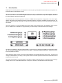
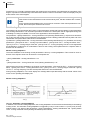
Building on a common platform, the temperature control system sysTemp® offers three different concepts for customized multi-zone temperature control.
The common platform of sysTemp® guarantees continuity with the configuration and parameterization, as well as
with the connection over the available digital interfaces. Every controller can have up to three digital interfaces in
this case: RS485, CAN-Bus, Profibus DP.
The powerful and universal temperature controller unit ETR 112 is designed for employment in hot runner applications, machines for the plastics processing, packaging machines, furnaces, foodstuffs processing, dryers, etc.
With its adaptive parameter matching, it can be used in a wide field of application from extremely fast to extremely
slow zones.
The ETR 112 with 12 or 16 zones (dependent on the number of the cooling zones), with additional inputs and outputs, is suitable for the realization of supplementary functions ideally for decentralized system designs.
The device is available in different implementations. This must be considered at installation and operational startup. You find more detailed references to that in the chapter ->Equipment implementation and ->Electrical connection and operational startup.
These directions assist, both in case of the initial installation and operational startup of the device, and in case of
changes and adaptations to existing control systems. Status and fault signals are described and remedial actions
proposed for their removal.
The protocol descriptions for serial interface, CAN-Bus, Profibus DP & DPEA are not a component part of the operating manual. You are provided with these on request or directly as a download from the home page.
Rev. 1.00.03
Right to technical changes reserved
3
4
Chapter 1
Introduction
1.1 Typographical conventions
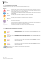
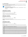
Symbols and conventions are used in this manual for faster orientation for you.
Symbols
Caution
With this symbol, references and information are displayed which are decisive for the operation of the device. In case of non-compliance with or inaccurate compliance there can
result damage to the device or injuries to persons.
Note
The symbol refers to additional information and declarations, which serve for improved
understanding.
Example
Reference
Tip
With the symbol, a function is explained by means of an example.
With this symbol, information in another document is referred to.
Here you get useful hints.
Cross references are marked with this character. In the pdf version of the document the
objective of the cross reference is reached via the link.
Equations
Calculation specifications and examples are represented in this way.
1.2 Additional and continuative documents
Protocol
PSG II
Information on this topic are in the protocol description PSG II and the corresponding object lists.
Protocol
Profibus DP & Profibus DPEA
Information on this topic are in the protocol description Profibus DP & Profibus DPEA and the corresponding object lists.
Protocol
Modbus
Information on this topic are in the protocol description Modbus and the corresponding object lists.
Protocol
CANopen
Information on this topic are in the protocol description CANopen and the corresponding object lists.
Data sheets and operating manuals
Available by Internet see www.psg-online.de .
Rev. 1.00.03
Right to technical changes reserved
PSG Plastic Service GmbH
Operating instructionsETR 112
2
General Information
2.1 Guarantee conditions
This product is subject to the legal warranty time periods for faults or deficiencies in manufacture.
Content of the guarantee
If a malfunction relatively occurs through the manufacture, the manufacturer repairs or replaces the nonconforming product, according to their own discretion.
The following repairs do not fall under the guarantee and liable to costs:
Malfunctions after the legal notice periods have expired.
Malfunctions caused through operating error of the user (if the device is not operated as described in the manual).
Malfunctions caused through other devices.
Changes or damage to the device which do not originate from the manufacturer.
If you wish to use services within the framework of this guarantee, please refer to the manufacturer.
2.2 Installation and safety references
Before installation, actuation or operation of the device, please read through this operating manual completely and carefully.
This device corresponds to the European Directives for Safety and EMC. It is within the sphere of responsibility of the commissioning engineer to keep to these directives during the installation of the device.
CE marking
The device complies with the European Directives for electromagnetic compatibility (complies with EN 61326-1).
Safety standard
This device corresponds to the European low-voltage guideline 73/23/EWG, extended through 93/68/EWG, subject to application of the Safety Standard EN 61010.
Electro-Magnetic Compatibility (EMC)
This device is in conformity with the EMC Directive 89/336/EWG, extended through 93/68/EWG and the necessary
protection requirements. The device is planned for applications in the industrial sector in accordance with EN
50081-2 and EN 500082-2.
Service and repair
This device is maintenance free.
If the device should indicate a fault, you please contact the manufacturer. Customer repairs are not permissible.
Cleaning
Employ no water or cleaning agents based on water for the cleaning of the device stick-on labels. You can clean
the surface of the devices with a mild soap solution.
Storage
If you should not put the device into operation immediately after unpacking, protect it against moisture and coarse
dirt.
Personnel
The installation of the device may by carried out by qualified personnel only.
Wiring
The wiring system must be implemented correctly according to the specifications in this operating manual. All
feeds and connecting terminals must be dimensioned for the corresponding amperage. Furthermore, all connections are to be carried out according to the valid VDE Specification and/or the respective national specifications.
Ensure in particular that the AC power supply is not connected with the logic output or the low-voltage input.
Rev. 1.00.03
Technical changes reserved
5
6
Chapter 2
General Information
Overload protection
Secure the power supply of the device and the relay output with a fuse protection or a power circuit-breaker. This
protects the printed circuit boards against overcurrent.
Environment
Conducting contamination must not reach the proximity of the device connecting terminals in the control cabinet.
In order to achieve suitable ambient air conditions, install an air filter in the air inlet of the control cabinet. If the
device should be in a condensing environment (low temperatures), install a thermostat-controlled heating unit in
the control cabinet.
Rev. 1.00.03
Technical changes reserved
PSG Plastic Service GmbH
Operating instructionsETR 112
3
Equipment implementation
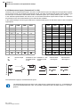
3.1 Type designation
The equipment of the device, over and beyond the standard type, is stipulated with the order. The exact specification can be read off on the ->Type designation plate type designation plate, which is on the carton, the casing
and the printed circuit board.
The type designation identifies the equipment version and is composed of the options.
ETR112
Electrical connections
K
FZ
Screwed terminal
Spring terminal
Melt pressure
MD
-
Melt pressure (only for X4/13/14 4-20 mA)
Not existing
Measurement inputs 13, 14 TCPt
TCPt/1300
U
I
Thermocouple TC / resistance thermometer Pt100
Thermocouple up to 1300 °C
Standardsignal U 0/2...10V
Standard signal I 0/4...20mA
Measurement inputs 15, 16 TCPt
TCPt/1300
U
I
Thermocouple TC / resistance thermometer Pt 100
Thermocouple up to 1300 °C
Standardsignal U 0/2...10V
Standard signal I 0/4...20mA
Data interface 2
CAN
CANopen
Not existing
Can-Bus with PSG-CAN plug assignment
CAN-Bus with CANopen-conforming connector pin assignment
Data interface 3
Profi
Not existing
Profibus DP
OPTION AO
AO
Not existing
Analog outputs 1...4
Voltage
24V
24 V AC/DC
Data interface 1 RS232 / RS485 is always existing as standard.
Rev. 1.00.03
Right to technical changes reserved
7
8
Chapter 3
Equipment implementation
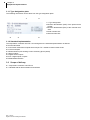
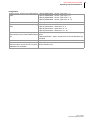
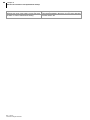
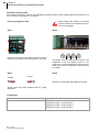
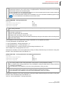
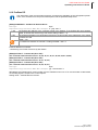
3.1.1 Type designation plate
The following information can be taken from the type designation plate:
1
4
1 ->Type designation
2 Revision identification (HW*) of the printed circuit
boards
3 Revision identification (SW*) of the controller software
4 Order number ANr.
5 Serial number SNr.
2
3
5
3.1.2 Standard implementation
The temperature controller unit ETR 112 is designed in the standard implementation as follows:
Screwed terminals
16 Universal measurement inputs thermocouple TC / resistance thermometer Pt100
24 Control outputs
3 Measurement inputs heating current monitoring (three-phase)
3 Alarm outputs
2 Digital function inputs
Each 4 digital inputs / outputs
RS232/RS485 interface
3.2 Scope of delivery
1 Temperature controller unit ETR112
1 CD-ROM with full documentation and software
Rev. 1.00.03
Right to technical changes reserved
PSG Plastic Service GmbH
Operating instructionsETR 112
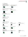
3.3 Accessories
Operation and display
BA operating and display unit
(Details, see data sheet)
Operator terminal BA Touch
Order number: 020 270
Output modules and power circuit-breakers
SMAO 04
Order number: 020 323
SMS 01
Order number: 020 332-5
SMK 02 / SMK 04
Order number: 020 218 / 020 219
Measured value recording
CANAIN 08
Order number: 020 365
Heating Current Monitoring
ESW 40
Order number: 039 014
ESW 75
Order number: 039 049
SSW 120P
Order number: 020 312-1
SUW
Order number: 020 315
ESW 200
Order number: 039 048
CAN accessories
CANVTM 2K / 4K
CANREP
Order number: 020 318 / 020 314-1 Order number: 020 317
CANDAT
Order number: 020 349-1
Rev. 1.00.03
Right to technical changes reserved
9
10
Chapter 3
Equipment implementation
Software / Online maintenance
WinKonVis
Order number: 039 020
Rev. 1.00.03
Right to technical changes reserved
WinKonVis Server
Order number: 039 021
webremote
Order number: 020 346
PSG Plastic Service GmbH
Operating instructionsETR 112
4
Device construction
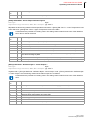
4.1 Dimensions
The ETR112 has a securing mechanism for the installation on DIN rail (DIN 50022) see ->Installation/Dismantling.
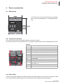
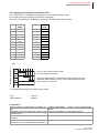
4.2 Connection overview
The connection overview here indicates all possible connection variants.
The actual connection overview depends on the ->Equipment implementation which is stipulated with the order.
ETR112
X1, X2
Measurement inputs 1...4 & 5...8 (TC / Pt100)
X3
Measurement inputs 9...12 (TC/Pt100)
X4
Measurement inputs 13...16 (TC/Pt100, analog inputs)
X5
X12
X5, X6
Control outputs 1...12, control outputs 13...24
X6
X13
X7
Alarm outputs 1...3, digital inputs 1...2
X8
Profibus DP
X9
RS485/ V24
X10
CAN-Bus
X11
Power supply
X12
3 Heating current inputs, OPTION analog outputs 3...4
X13
Digital inputs 1...4, digital outputs 1...4, OPTION analog outputs 1..2
A
Status LED's
B
DIP switch
X7
X1
X8
A
X9
X10
X1
B
X11
X2
X1
X4
X1
X3
4.2.1 Status LED's
The SIO-LED (yellow) signalizes the interface operation and flashes quicker or slower due to the amount of data.
In the normal case the OK-LED (green) on the front panel of the controller lights up permanently.
Rev. 1.00.03
Right to technical changes reserved
11
12
Chapter 4
Device construction
The LED flashes if there is a fault. The cause of error can be read off on the basis of the number of flashing signals.
Detailed information about the error cause can be referred to in the chapter ->System errorand ->Summary of system errors / flashing codes OK-LED
4.2.2 DIP switch
Detailed information on the function of the DIP switches are in the chapter ->Addressing and Further Functions by
DIP Switch
Rev. 1.00.03
Right to technical changes reserved
PSG Plastic Service GmbH
Operating instructionsETR 112
5
Installation/Dismantling
ESD Avoidance
To avoid ESD damages the device must be handled, packed,
unpacked and stored in an especially protected environment
(Electrostatic Protected Area, EPA). An ESD-protected work
environment conducts existing electrostatic charges to ground in a
controlled manner and prevents their re-occurrence.
Unpacking
The device is packed fully-mounted in a robust carton, cushioned with
foamed material.
Check the packaging and then the device for identifiable damage incurred during transit. If damage is identified, then please get in touch
with the transportation company.
In the case of damage the device may not be brought into operation.
Ensuring voltage-free state
Before beginning and during all installation/dismantling work,
attention is to be paid that the system, as well as the devices,
are de-energized
Installation location
A device of the protection type IP20 is to be installed in a closed control
cabinet.
Securing
The device has a securing mechanism for installation on a DIN rail
(DIN 50022).
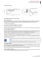
Installation/Dismantling
The device is initially suspended in the DIN rail with the two straps
(rear/middle side) and then latched in. For dismantling, the unlocking
mechanism on the front below at the device (Illustration) is to be
screwed down with a screwdriver and the device taken out towards the
front/above.
Device exchange
Only controllers of similar type may be exchanged. In case of
replacement, it is absolutely necessary to adopt the setting
adjustments of the replaced controller.
Rev. 1.00.03
Technical changes reserved
13
14
Chapter 6
Electrical connection and operational startup
6
Electrical connection and operational startup
The ETR112 may be installed and put into operation by specialist personnel only.
Before switch-on of the control zones it is to be ensured that the ETR112 is configured for the application. An incorrect configuration can lead to damage to the control section or to injuries to persons.
6.1 Connection type
In the standard type the device is equipped with screwed terminals. The terminals existing on the device are to be
taken from the ->Type designation
The following plugs of the Co. Phoenix Contact are employed for the individual connections:
Connection
Type designation
Plug for screwed terminal
Type designation
OPTION Plug for spring terminal
X1...X4
MCVR 1.5/13-STF-3.81
FK-MCP 1.5/13-STF-3.81
X5...X6
MCVR 1.5/14-STF-3.81
FK-MCP 1.5/14-STF-3.81
X7
MCVR 1.5/10-STF-3.81
FK-MCP 1.5/10-STF-3.81
X11
MVSTBW 2.5 HC/3-STF-5.08
FKC 2.5 HC/3-STF-5.08
X12...X13
MCVR 1.5/12-STF-3.81
FK-MCP 1.5/12-STF-3.81
The wiring system is implemented on the screwed terminals and spring terminals with the appropriate cable lugs.
Cables with a cross section of 0.5 to 1.5mm2 can be employed.
The terminal marking was modified. Here you find the new/old (identified by NEW/OLD) terminal marking described.
Rev. 1.00.03
Technical changes reserved
PSG Plastic Service GmbH
Operating instructions ETR112
6.2 Connector assignment and basic configuration
6.2.1 Power supply (Connection X11)
6.2.1.1
DC voltage
AC voltage
Power supply
X11
Power Supply 24 V
Power consumption
Max. 25 VA on load
Fuse protection
External device fuse protection 4 A time-delay
6.2.2 Auxiliary voltage (Connection X7)
The auxiliary voltage could be employed as power supply for ->Control Outputs (Connection X5, X6), ->Digital Input (Connection X7, X13) and ->Digital outputs (Connection X7, X13.
Auxiliary voltage
X7
Do not ground externally!
Output current
max. 1.5 A
Rev. 1.00.03
Technical changes reserved
15
Chapter 6
Electrical connection and operational startup
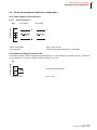
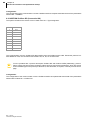
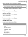
6.2.3 Measurement inputs (Connection X1 to X4)
The device has 16 measurement inputs. The first 12 measurement inputs are designed for temperature registration by thermocouple TC/ resistance thermometer Pt100. The other 4 measurement inputs can be either of type
thermocouple TC/ resistance thermometer Pt100 or standard signal I (0/4...20mA) and/or U (0/2...10VDC).
In the standard implementation the device has 16 universal measurement inputs thermocouple TC/ resistance
thermometer Pt100. Per measurement input 3 terminals are available.
In the system setting the sensor type is defined for 4 measurement inputs, as well as the scale in case of standard
signal inputs.
PIN
X1
NEW
X2
NEW
X3
NEW
X4
NEW
PIN
X1
OLD
X2
OLD
X3
OLD
X4
OLD
1
1+
5+
9+
13+
1
1+
5+
9+
13+
2
1-
5-
9-
13-
2
1-
5-
9-
13-
3
1
5
9
13
3
0V
0V
0V
0V
4
2+
6+
10+
14+
4
2+
6+
10+
14+
5
2-
6-
10-
14-
5
2-
6-
10-
14-
6
2
6
10
14
6
0V
0V
0V
0V
7
3+
7+
11+
15+
7
3+
7+
11+
15+
8
3-
7-
11-
15-
8
3-
7-
11-
15-
9
3
7
11
15
9
0V
0V
0V
0V
10
4+
8+
12+
16+
10
4+
8+
12+
16+
11
4-
8-
12-
16-
11
4-
8-
12-
16-
12
4
8
12
16
12
0V
0V
0V
0V
13
X1
to
X4
13
Thermocouple
TC
Resistance ther- Resistance thermometer Pt100 mometer Pt100
2-wire
3-wire
OPTION Standard signal I
OPTION Standard signal U
Measurement input
16
The specifications apply for all measurement inputs.
The standard signal inputs U and/or I are optional for the measurement inputs 13...16 available and
have to be stipulated with the order. The possible combinations are to be taken from the ->Type designation.
Rev. 1.00.03
Technical changes reserved
PSG Plastic Service GmbH
Operating instructions ETR112
configuration
Arrange sensor type for the measurement ->[SP20] SEN1/SEN1 - Sensor Type Zone 1...4
inputs.
->[SP21] SEN2/SEN2 - Sensor Type Zone 5...8
->[SP22] SEN3/SEN3 - Sensor Type Zone 9...12
->[SP23] SEN4/SEN4 - Sensor Type Zone 13...16
Stipulate offset valid for all zones.
->[P029] OFFS/OFFS - Temperature Offset
Stipulate offset valid for the corresponding ->[SP30] OFF1/OFF1 - Offset Zone 1...4
zones.
->[SP31] OFF2/OFF2 - Offset Zone 5...8
->[SP32] OFF3/OFF3 - Offset Zone 9...12
->[SP33] OFF4/OFF4 - Offset Zone 13...16
Stipulation of the measuring range, when ->[P042] ANZ-/RG L - Lower Temperature Level at Standard Signal
measurement input is of the standard signal Inputs
type.
->[P043] ANZ+/RG - Upper Temperature Level with Standard Signal Inputs
Stipulate units of all measured values.
->[SP24] CELS/CELS - Temperature Unit °C/°F
Specification of the measuring channel, if ->[P057] NrIW/NoZN - Zone Allocation to Measurement Input on
measured value comes from a FIN 08 or Sensor Interface FIN
CANAIN08 over CAN-Bus.
Rev. 1.00.03
Technical changes reserved
17
Chapter 6
Electrical connection and operational startup
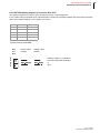
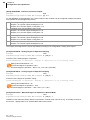
6.2.4 Control Outputs (Connection X5, X6)
The allocation of the control outputs Heating/Cooling is defined by system setting.
PIN
X5
NEW
X6
NEW
PIN
X5
OLD
X6
OLD
1
U1
U1
1
+U
+U
2
U2
U2
2
+U
+U
3
O01
O13
3
O01
O13
4
O02
O14
4
O02
O14
5
O03
O15
5
O03
O15
6
O04
O16
6
O04
O16
7
O05
O17
7
O05
O17
8
O06
O18
8
O06
O18
9
O07
O19
9
O07
O19
10
O08
O20
10
O08
O20
11
O09
O21
11
O09
O21
12
O10
O22
12
O10
O22
13
O11
O23
13
O11
O23
14
O12
O24
14
O12
O24
X5 and X6
Control output
18
Auxiliary voltage U+ from connection X7/8 or Uext
Auxiliary voltage U- from connection X7/9 or 0Vext.
The specifications apply for all control outputs.
Rated voltage
30VDC
Rated output current
<= 60mA
Inductive load only with external free-wheeling diode
Configuration
Definition, which digital outputs are as- ->[SP52] ODEF/ODEF - Definition of Control Outputs
signed to which control zone.
Define the operating mode of the control ->[P034] KHLG/COOL - 3-Point Operation
zone.
Stipulates the manner in which the actuat- ->[P035] RELH/RELH - RELH/RELH - Heating Relay Output
ing signal is output at the control output.
->[P036] RELK/RELC - Cooling Relay Output
Is the cooling output used as alarm output, ->[P038] AZD1/AZD1 - Alarm Output Definition Byte 1
stipulate which alarm is output on the cool- ->[P039] AZD2/AZD2 - Alarm Output Definition Byte 2
ing output.
Rev. 1.00.03
Technical changes reserved
PSG Plastic Service GmbH
Operating instructions ETR112
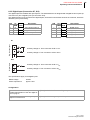
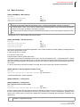
6.2.5 Digital Input (Connection X7, X13)
The digital inputs are realized with optocouplers. The standard device is designed with 2 digital function inputs (at
connection X7) and 4 digital inputs (at connection X13).
The digital function inputs, as well as the digital inputs, work with functions fixed stored in the controller, which are
defined by the system setting.
PIN
X7
NEW
X7
OLD
Description
PIN
X13 X13
NEW OLD
Description
1
I2
IN2
Dig. function input 2
7
I1
DI1
Digital input 1
2
I1
IN1
Dig. function input 1
8
I2
DI2
Digital input 2
3
I-
IN-
Reference potential I *
9
I3
DI3
Digital input 3
10
I4
DI4
Digital input 4
Dig. function input
X7
Auxiliary voltage U+ from connection X7/8 or Uext
Auxiliary voltage U- from connection X7/9 or 0Vext
Digital input
X13
Auxiliary voltage U+ from connection X7/8 or Uext
Auxiliary voltage U- from connection X7/9 or 0Vext
The specifications apply for all digital inputs.
Rated voltage
30VDC
Power requirement
approx. 5mA
Configuration
Stipulate function which is implemented on ->[SP25] INPD/INPD - Function of Digital Inputs
activation/deactivation of the two digital inputs on plug X7.
Stipulates the function of the digital inputs/ ->[SP51] DIO /DIO - Digital Inputs / Outputs
outputs on terminal X13
Rev. 1.00.03
Technical changes reserved
19
Chapter 6
Electrical connection and operational startup
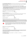
6.2.6 Digital outputs (Connection X7, X13
The digital outputs are realized with optocouplers. The standard device is designed with 3 alarm outputs (at connection X7) and 4 digital outputs (at connection X13).
In the system setting is defined which alarms are output on the outputs and which function the digital outputs have.
PIN
X7
Description
PIN
4
AL3
Alarm Output 3
3
O1
DO1
Digital output 1
5
AL2
Alarm Output 2
4
O2
DO2
Digital output 2
6
AL1
Alarm output 1
5
O3
DO3
Digital output 3
7
AL+
Power supply alarm outputs
6
O4
DO4
Digital output 4
X13 X13
NEW OLD
Description
Terminal marking OLD=NEW
Alarm output
X7
Auxiliary voltage U+ from X7/8 or Uext
X13
Digital output
20
Auxiliary voltage U+ from X7/8 or Uext
Auxiliary voltage U- from connection X7/9 or 0Vext.
The specifications apply for all digital outputs.
Rated voltage
30VDC
Rated output current
<= 60mA
Inductive load only with external free-wheeling diode
Configuration
Stipulate function of the alarm output 1.
->[SP10] A1D1/A1D1 - Definition Byte 1 - Alarm Output 1
->[SP11] A1D2/A1D2 - Definition Byte 2 - Alarm Output 1
->[SP12] A1D3/A1D3 - Definition Byte 3 - Alarm Output 1
Stipulate function of the alarm output 2.
->[SP13] A2D1/A2D1 - Definition Byte 1 - Alarm Output 2
->[SP14] A2D2/A2D2 - Definition Byte 2 - Alarm Output 2
->[SP15] A2D3/A2D3 - Definition Byte 3 - Alarm Output 2
Stipulate function of the alarm output 3.
->[SP16] A3D1/A3D1 - Definition Byte 1 - Alarm Output 3
->[SP17] A3D2/A3D2 - Definition Byte 2 - Alarm Output 3
->[SP18] A3D3/A3D3 - Definition Byte 3 - Alarm Output 3
Rev. 1.00.03
Technical changes reserved
PSG Plastic Service GmbH
Operating instructions ETR112
6.2.7 Heating Current Inputs (connection X12)
The standard device is designed for registration of three 3-phase heating currents.
In the system setting the measurement method is stipulated.
Use the current transformers available as accessories by PSG Plastic Service GmbH.
PIN
X12
NEW
PIN
X12
OLD
1
n.a.
1
n.a.
2
n.a.
2
n.a.
3
C11
3
I11
4
C12
4
I12
5
C13
5
I13
6
C21
6
I21
7
C22
7
I22
8
C23
8
I23
9
C31
9
I31
10
C32
10
I32
11
C33
11
I33
12
C0V
12
0V
Heating current input
X12
Do not connect C0V system overall!
Do not ground C0V terminal!
Using the supply voltage measurement module SUW the system
parameter SUW defines, on which current measurement input the
SUW module is connected.
The specifications apply for all heating current inputs
.
Input
42mV/A
Input resistance
20kOhm
Configuration
Specify method of measurement of heating cur- ->[SP26] ADEF/AMPD - Heating Current Measurement
rent.
Method
Comparative value for the heating current of the ->[P007] ASOL/AMPN - Current Setpoint Value
measured zone.
Stipulate tolerance value for control of heating cur- ->[P006] ATOL/AMPT - Current Tolerance
rent value.
Stipulate the measurement input where the current ->[P056] SUMW/NoTR - Allocation of Current Transformer
transformer of the controlled zone is connected to.
Rev. 1.00.03
Technical changes reserved
21
22
Chapter 6
Electrical connection and operational startup
Stipulate the scale of the measurement input.
->[Zone 041] AEND/AMPE - Current Range End Value
Stipulate the value of the heating current that rises ->[SP37] MSAA/AMPM - Maximum Current Value with Meaan alarm in case of switched-off heating.
surement Heater Off
Rev. 1.00.03
Technical changes reserved
PSG Plastic Service GmbH
Operating instructions ETR112
6.2.8 Data interface RS232/RS485 (Connection X9)
The standard device is designed with the serial RS232/RS485 data interface.
RS232
RS485
PIN
X9
PIN
X9
1
n.a.
1
TxD-P
2
n.a.
2
TxD-N
3
TxD-V24
3
n.a.
4
n.a.
4
n.a.
5
n.a.
5
RxD-N
6
n.a.
6
RxD-P
7
n.a.
7
n.a.
8
RxD-V24
8
n.a.
9
GND-V24
9
n.a.
Galvanically isolated (24 V).
Galvanically not isolated
(230 V).
Only for purpose of configuration.
Galvanically isolated.
2/4-wire.
In the case of 2-wire operation:
Connect Pin 1 and 6,
as well as Pin 2 and 5.
The communication over serial data interface uses the protocol PSGII and Modbus. You are provided
with a protocol description PSGII and Modbus (addressing, protocol frame, logging function) and the
respective object list (zone and system parameters, which are stored for the controller type in the protocol) of the device, as a download, on request, or directly from the home page.
Configuration
The configuration of the communication over the serial data interface is implemented with the aid of the parameters listed under ->Serial data interface.
6.2.9 CAN-Bus (connection X10)
The options included in the device are to be taken from the ->Type designation.
PIN
X10
PSG-CAN
PIN
X10
CANopen
1
+U
1
n.a.
2
n.a.
2
CAN-L
3
n.a.
3
n.a.
4
n.a.
4
n.a.
5
GND
5
n.a.
6
n.a.
6
n.a.
7
CAN-L
7
CAN-H
8
n.a.
8
n.a.
9
CAN-H
9
n.a.
The communication over the CAN-Bus uses the protocol CANopen. You are provided with an object
list (zone and system parameters which are stored for the controller type in the protocol) of the device,
as a download, on request, or directly from the home page.
CAN-Bus termination: Connecting Pin3 and Pin4 on terminal X10 activates the internal CAN-Bus termination impedance of 120 Ohm.
Rev. 1.00.03
Technical changes reserved
23
24
Chapter 6
Electrical connection and operational startup
Configuration
The configuration of the communication over the CAN-Bus interface is implemented with the aid of the parameters
listed under ->CANBUS
6.2.10OPTION Profibus DP (Connection X8)
The options included in the device are to be taken from the ->Type designation.
PIN
X8
1
n.a.
2
n.a.
3
TxD-B
4
RTS
5
0V
6
+5VDC
7
n.a.
8
TxD-A
9
n.a.
The communication over the Profibus DP data interface uses the Profibus protocol DP. Should the protocol Profibus DPEA be used, the controllers with firmware 22, 23, 26, 27 must be used.
You are provided with a protocol description Profibus DP and Profibus DPEA (addressing, protocol
frame, logging function) and the respective object list (zone and system parameters, which are stored
for the controller type in the protocol) of the device, as a download, on request, or directly from the home
page.
Configuration
The configuration of the communication over the Profibus interface is implemented with the aid of the parameters
listed under Profibus DP.->Profibus DP
Rev. 1.00.03
Technical changes reserved
PSG Plastic Service GmbH
Operating instructions ETR112
6.2.11OPTION Analog Outputs (Connection X12, X13)
The options included in the device are to be taken from the ->Type designation.
In the system setting is defined which values/function is output on the analog outputs and which lower limit value
refers to the output range (0 or 4mA and/or 0 or 2VDC).
PIN
X12
X13
1
AO3
AO1
2
AO4
AO2
3...10
n.a.
n.a.
11
n.a.
+U
12
n.a.
-U
Terminal marking OLD=NEW
Analog output
X12
and
X13
Analog output
Voltage
Analog output
Current
Auxiliary voltage -U connection
X7/9 !Do not ground externally!
or
0Vext
Rev. 1.00.03
Technical changes reserved
25
26
Chapter 6
Electrical connection and operational startup
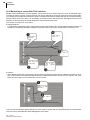
Adjustment analog output
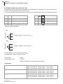
Each analog output AO1...AO4 can be stipulated by jumper as analog output voltage (standard ex-works) or current. Under the casing there are 4 jumpers.
Before starting the setting of the analog
outputs, attention is to be paid that the device is de-energized.
Ensuring voltage-free state
Step 1
Step 2
Remove the 4 screws of the casing. Detach the casing
carefully (if necessary remove terminal X7, X11 first).
Step 3
Voltage
The jumper are on the left side of the device. The
assignment of the 12 jumpers is done in four
groups of 3, from the left side to the right. In this example AO1 to AO4 are stipulated as analog output
for voltage.
Step 4
Current
Attach the casing again and tighten the screws.
Analog output AO1-AO4 voltage/current by jumper
adjustable.
Configuration
Adjust measuring range of analog outputs.
->[SP46] AOFF/AOFF - Offset Analog Outputs
Stipulate function of the analog outputs.
->[SP47] AO1 /AO1 - Analog Output 1
->[SP48] AO2 /AO2 - Analog Output 2
->[SP49] AO3 /AO3 - Analog Output 3
->[SP50] AO4 /AO4 - Analog Output 4
Rev. 1.00.03
Technical changes reserved
PSG Plastic Service GmbH
Operating instructions ETR112
7
Addressing and Further Functions by DIP Switch
Using the DIP switch, the following configuration of the system and functions like e.g. acknowledgement can be
carried out.
7.1 Addressing
The address consists of device ID (binary coded; setting by DIP switch) and an interface specific base part (setting
by system parameter in engineering tool WinKonVis).
Based on the used firmware version (S and/or SD) for the serial interface can be chosen between static and dynamic addressing.
Firmware Version SD
Static/Dynamic Addressing
Firmware Identifier
ETR112 20, 22, 24, 26
Firmware Version S
Static Addressing
Firmware Identifier
21, 23, 25, 27, 28, 2T
Firmware Version S
The device ID is adjusted by the DIP switches 1...4.
Firmware Version SD
The device ID is adjusted by the DIP switches 1...5.
The selection of the addressing type is done by DIP switch 6
(static: DIP switch 6 = OFF, dynamic: DIP switch 6 = ON).
Static Addressing of Serial Interface (Firmware Version S and/or SD & DIP 6 = OFF)
At static addressing 8 zones are addressed by 1 address.
For the controller the zone number is defined by 32. The 32 zones therefore reserve 4 addresses.
The address of the controller is dependent on the DIP switch a multiple of 4.
Dynamic Addressing of Serial Interface (Firmware SD & DIP 6 = ON)
At dynamic addressing 8 zones are addressed by one address.
For the controller ETR112 the zone number is defined by 32. The 32 zones therefore reserve 4 addresses. The
DIP switch has to be set accordingly.
Rev. 1.00.03
Right to technical changes reserved
27
28
Chapter 7
Addressing and Further Functions by DIP Switch
Interface
Resulting
Address/NodeID
Serial PSGII/ Modbus RTU Serial Address
Base part of
Address/NodeID
=
Device ID
by (DIP switch 1...4) x 4
at Firmware Version S
(32 zones = 4 addresses)
Serial Address
=
Device ID
0
=
0
4
=
1
8
=
2
etc.
Serial PSGII/ Modbus RTU Serial Address
etc.
=
Device ID
by (DIP switch 1...5) x 4
DIP switch 6 = OFF
at Firmware Version SD - static
(32 zones = 4 addresses)
Serial Address
=
Device ID
0
=
0
4
=
1
8
=
2
etc.
Serial PSGII/ Modbus RTU Serial Address
etc.
=
Device ID
by (DIP switch 1...5)
DIP switch 6 = ON
at Firmware Version SD - dynamic
(32 zones = 4 addresses)
Serial Address
=
Device ID
0
=
0
4
=
4
8
=
8
etc.
PSG-CAN
CAN-NodeID
etc.
=
CANopen base address CADR + device ID
by (DIP switch 1...5, and/or 1...4)
PSG Plastic Service GmbH
Operating instructions ETR112
CANopen
CAN-NodeID
=
CANopen base address CADR + device ID
by (DIP switch 1...5, and/or 1...4)
Profibus DP & DPEA
Profibus DP
Slave address
=
=
DPAD/DPAD < 128
Profibus DP Slave Address DPAD + Device ID
by (DIP switch 1...5, and/or 1...4)
DPAD/DPAD >= 128
Profibus DP slave address DPAD - 128
Rev. 1.00.03
Right to technical changes reserved
29
30
Chapter 7
Addressing and Further Functions by DIP Switch
7.2 DIP switch
The DIP switch setting differs from firmware version to firmware version.
Addressing Firmware Version S
CAN baud rate
Activation of default setting
1
8
Activation of default setting
Selection of addressing type
Addressing Firmware Version SD
DIP 5...6
Baud rate CAN (only for firmware version S)
The setting of the CAN baud rate for firmware version SD is done by system parameter ->[SP05] CANB/CANB - CAN Baud Rate.
DIP 1...5 and 7
Default setting for CANopen
The default setting by system parameter CANB for CANopen is only valid for
controllers with firmware version SD.
If the DIP switches 1...5, as well as DIP switch 7 = ON, the following default settings for CANopen are activated.
Default setting CANopen (X10):
CANB = Default of manufacturer
CADR = 32
A-OP = ON
OPEN = ON
PSG Plastic Service GmbH
Operating instructions ETR112
DIP 7
Default Setting for Serial Interface
If the DIP switch 7 = ON, the following default settings for the serial interface are
activated.
Default setting serial data interface (X9):
Address like set by DIP switch 1...5 and/or 1...4
Protocol PSGII
Baud rate 19200 Baud
No Parity
1 Stop bit
DIP 7
Acknowledge Error Messages
By setting of DIP switch 7 from OFF to ON (1.), waiting 3 seconds, and again to
OFF (2.), the acknowledgement of pending error messages is initiated.
.
Rev. 1.00.03
Right to technical changes reserved
31
32
Chapter 8
Status displays/diagnostics
8
Status displays/diagnostics
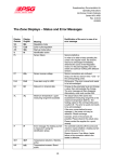
8.1 Information 'zone text'
In case of certain operational states of the controller, a text is overlaid alternately with the actual value in the zone
display of the operating and display units. This text can be read out under the byte ZoneFMode for every zone
over all interfaces. The information is also designated as a zone text.
Since only the zone text with the highest priority can always be displayed, the zone text is to be considered exclusively as an extension to the status information of a zone. The byte ZoneFMode includes the following information:
Bit
on
off
0...5
Zone text ->Overview of zone texts
6
Control zone has correct model of the control Control zone does not have any correct model of
zone. At least a ->[P031] IDEN/IDEN - Heating the control zone. No ->[P031] IDEN/IDEN - Heating
Identification has been successfully carried out.
Identification has yet been successfully carried out.
7
Zone active.
Zone passive.
8.1.1 Overview of zone texts
Signal
flag
(dec)
Display Meaning
1
Ma
Manual mode
x
2
CoU
Leading zone manual mode
x
3
AbS
Reduction
x
4
rAP
Temperature Ramp
x
5
StA
Startup operation
x
6
Alarm Status
Without function
7
Id
Identification
x
8
IdC
Cooling adaptation
x
9
tCb
Sensor break
x
10
TCAL
Sensor short-circuit
x
11
tcP
Sensor incorrect polarity
x
12
CAn
Fault in CAN communication
x
13
Err
System error/ fault in channel data
x
14
AL
Exceeded maximum temperature/ upper limit of measuring range
x
15
Pld
Plausibility violation during the identification
x
16
drl
Drift error report during identification phase
x
17
IF
Error report "No heating current measured" during identification phase
18
SP2
2nd setpoint value
x
19
SP3
3rd setpoint value
x
20
SP4
4th setpoint value
x
21
dF1
Fault "No current" determined in case of "Heating current" diagnostics
22
dF2
Fault "Current on incorrect zone" determined in case of "Heating current"
diagnostics
x
23
dF3
Fault "Current both on correct as well as on another zone" determined with
"Heating current" diagnostics
x
24
dE
No fault determined with "Heating current" diagnostics / "Allocation sensor/
heating" diagnostics ends
x
25
dIA
Diagnostics function active
x
Rev. 1.00.03
Technical changes reserved
x
x
PSG Plastic Service GmbH
Operating instructions ETR112
Signal
flag
(dec)
Display Meaning
26
dF4
Fault "Alarm current with switched off heating" determined in case of diagnostics
x
27
Ar
Automatic ramp
x
28
Ar.
Automatic ramp active, zone with least temperature rise
x
29
I-
Alarm "Current alarm with heating off"
x
30
ALS
Storing alarm function
x
31
IdS
Automatic cooling adaptation started, however still not active
32-33
Alarm Status
x
Without function
34
000
35
001
Error signal
x
36
002
Module matching system error
x
37
003
CPU adjustment fault
x
38
004
39
005
Fault in system data
x
40
006
41
007
42
008
Switch-on configuration
x
43
009
Switch-on configuration sensor
x
44-49
Without function
50
Out
Power controller disconnected (Digital Input 2 active and system parameter
INPD equal to 0 or 1)
51
CuI
CAN error in data link controller/CANSTI
x
x
Rev. 1.00.03
Technical changes reserved
33
34
Chapter 8
Status displays/diagnostics
8.2 System error
Unlike zone-specific faults (temperature limit values, heating current alarms, etc.) system errors identify faults on
the controller itself. The system errors can be read out from the controller on the zone flags over all interfaces.
Detailed information on this can be found n the object lists for the corresponding protocols.
The cause of error, the output of the OK-LED on the controller, the message text in the operating and display units,
as well as notes on the elimination of the fault, are indicated below for all possible system errors.
Fault in the CPU basic matching
If the basic matching of the controller cannot be read correctly any longer, then the bit "Fault in the basic matching"
is set.
On all zones of the controller a degree of operation of 0% is output.
On the OK-LED of the controller a flashing signal is output.
With the operating and display units, ERR 003 is displayed.
For the removal of the fault, the controller is to be set to the ex-works state (Code Number 759). Before resetting
into the ex-works state, all channel data and system data are to be noted down or read out and stored with
WinKonVis.
Fault in the module matching
The module matching data items in the controller unit . If these cannot be read correctly any longer, then the bit
"Fault in the module matching" is set.
On all zones of the module, a degree of operation of 0% is output.
If a "fault in the module matching" is identified for the zones 1 to 4, then two flashing signals are output at the
OK-LED of the controller.
If a "fault in the module matching" is identified for the zones 5 to 8, then three flashing signals are output at the
OK-LED.
If a "fault in the module matching" is identified for the zones 9 to 12, then four flashing signals are output at the
OK-LED.
If a "fault in the module matching" is identified for the zones 13 to 16, then five flashing signals are output at the
OK-LED.
With the operating and display units, ERR 002 is displayed.
For the removal of the fault, the controller is to be set to the ex-works state (Code Number 759). Before resetting
into the ex-works state, all channel data and system data are to be noted down or read out and stored with
WinKonVis.
Fault in channel data
For the assurance of the data consistency and the data security, a checksum is stored for every zone in case of
storage of the configuration data into the EEPROM.
The bit „Fault in channel data“ is activated, when the controller detects a check sum error during reading of channel
data.
If a "Fault in channel data" is identified, seven flashing signals are output on the OK-LED.
With the operating and display units, ERR is displayed in the zone display.
For the removal of the fault, all zone-specific configuration parameters are to be checked, a value changed and
the change stored in the EEPROM. After this, wait 20 seconds and carry out a controller reset (e.g. over code
number 999). After the regulator restart, the fault should have disappeared.
Alternatively, the controller can be set into the ex-works state (Code Number 759). Before resetting into the exworks state, please note down all channel data and system data or read out and store with WnKonVis.
If the fault reappears after the reset, then there is a hardware fault in the EEPROM. The controller must be sent
in for repair.
Rev. 1.00.03
Technical changes reserved
PSG Plastic Service GmbH
Operating instructions ETR112
Fault in System data/ Attributes
The system data is stored grid-failure-secure in the EEPROM of the controller. The bit "Fault in system data/attributes" is set if data change without external intervention.
On all zones of the controller a degree of operation of 0% is output.
If a "Fault in system data/attributes" is identified, then six flashing signals are output on the OK-LED.
With the operating and display units, ERR 005 is displayed.
For the removal of the fault, all system data and attributes are to be checked, a value changed and the changes
taken over into the EEPROM. After this, wait 20 seconds and carry out a controller reset (e.g. over code number
999). After the regulator restart, the fault should have disappeared.
Alternatively, the controller can be set into the ex-works state (Code Number 759). Before resetting into the exworks state, all channel data and system data are to be noted down or read out and stored with WinKonVis.
If the fault reappears after the reset, then there is a hardware fault in the EEPROM. The controller must be sent
in for repair.
CAN-Bus fault
A fault CAN-Bus occurs, for example, when data which should be received by the controller over CAN-Bus controller (e.g. measured values of FIN 08 or CANAIN 08) does not reach the controller or CAN components corresponding to the controller cannot be identified by the controller.
In case of a fault on the CAN-Bus, eight flashing signals are output on the OK-LED.
In case of the operating and display units, CAN is displayed in the zone displays.
For elimination of the fault all cable connections, settings of CAN baud rate, address settings have to be checked.
Detailed information on the error location (among other things) can be found in the planning instructions
of an ETS control system. You are provided with the document, on request, or directly as a download
from the home page.
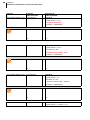
8.2.1 Summary of system errors / flashing codes OK-LED
Cause of error
Number of flashing Display of operating and display units
signals
Fault in the CPU basic matching
1
ERR 003
Fault in the module matching Zone 1 to 4
2
ERR 002
Fault in the module matching Zone 5 to 8
3
ERR 002
Fault in the module matching Zone 9 to 12
4
ERR 002
Fault in the module matching Zone 13 to 16
5
ERR 002
Fault in EEPROM
Fault in system data/ Attributes
ERR 004
6
ERR 005
ERR 009
Fault sensor type
(A sensor type is adjusted for the device, that
is not supported by the device/calibration.
The error report can be acknowledged (see >Addressing and Further Functions by DIP
Switch).
Check the setting of the sensor type after acknowledgement.
Fault in channel data
7
ERR
CAN-Bus fault
8
CAN
Rev. 1.00.03
Technical changes reserved
35
36
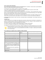
Chapter 9
Configuration and adjustments
9
Configuration and adjustments
With the configuration parameters, zone (and/or channel) parameters and system parameters are distinguished
between. Zone parameters are separately adjustable for every zone of the controller, while system parameters
apply zone-independently for the entire controller.
Parameters are functionally collated in the description. The identification of a parameter is implemented over the
following:
the designation of the configuration parameter as zone [P***] and/or system parameter [SP**],
a characteristic analog for the identification of the parameter in the parameter lists of the project planning and
configuration tool WinKonVis
The parameter mnemonics (German/English), which are employed for the identification in the operating and
display units BA and in the project planning and configuration tool WinKonVis (WKV),
the parameter label,
the data type (Bit, Byte, Char, Word, Integer) and bytes occupied by the data type
the setting range over the interfaces, WinKonVis and over the operating and display units BA (if these are identical, the setting range is indicated only once) and a multiplication factor that is to be considered.
a unit (when existent)
The ex-works basic setting of a parameter is identified through a bracket (e.g. [on]).
The handling of, as well as the access to, the parameters over the data interfaces (serial interface
[PSGII, MODBUS], CAN-Bus, Profibus DP [Standard, DPEA]) are to be taken from the protocol descriptions, as well as from the relevant parameter object lists.
The maximum setting range of a parameter is stipulated through its data format. In general, the maximum possible setting range is functionally limited. This is indicated as a setting range for the interfaces.
The detailed information on the data formats and ranges of values of the parameters are also to be
found in the object lists to the interfaces.
Has the parameter for controllers with other firmware another characteristic analog, a further line is
added and the appropriate firmware version is itemized.
9.1 Basic configuration
[P050] ZONE/ZONE - Zone
[P048] ZONE/ZONE - Zone
(For controller with firmware: 86, 88)
Data type
Adjustment range interfaces
Adjustment range WKV
Adjustment range BA
Bit
[0], 1
[on], oFF
[on], oFF
For reasons of compatibility to controllers of older generations, the adjustment value is over interface
in reverse logic.
1
At control output in accordance with operating mode (control/manual mode) actuating signals are output.
All alarms are calculated.
[0]
At control outputs no actuating signals are output.
No alarms are calculated.
Rev. 1.00.03
Technical changes reserved
PSG Plastic Service GmbH
Operating instructions ETR112
[P034] KHLG/COOL - 3-Point Operation
Data type
Adjustment range interfaces
Adjustment range WKV
Adjustment range BA
Bit
0, [1]
oFF, [on]
oFF, [on]
0
The control algorithm works in two-point operation (heating). The output range of the degree of operation
in control and manual mode is 0...100%.
At the heating control output, actuating signals are output at positive setting levels, at the cooling output no
actuating signal is output.
[1]
The control algorithm works in three-position operation (heating/cooling). The output range of the degree
of operation in control and manual mode is -100...100%.
On the heating control output, actuating signals are output at positive setting levels and, on the cooling output the actuating signals are output at negative setting levels
[SP24] CELS/CELS - Temperature Unit °C/°F
Data type
Adjustment range interfaces
Adjustment range WKV
Adjustment range BA
Char
0, [1]
°F, [°C]
oFF, [on]
Unit of measurement signal.
The measured value is calculated directly in case of controllers with thermo-element and resistance thermometer
inputs. In case of controllers with standard signal inputs, the calculation is implemented on the basis of the scaling
parameters ->[P042] ANZ-/RG L - Lower Temperature Level at Standard Signal Inputs and ->[P043] ANZ+/RG Upper Temperature Level with Standard Signal Inputs
[SP41] MAXK/MAXK – Maximum Number of Channels
Data type
Byte
Adjustment range interfaces, WKV, BA / multiplier 1...[32] / 1
The parameter stipulates the zone number for which the regulation, as well as the alarm handling, is processed,
starting from the first zone. The reduction of the zone number does not have any effect on the cycle duration in
case of recording of the measured values.
9.2 Configuration inputs
[SP20] SEN1/SEN1 - Sensor Type Zone 1...4
Data type
Adjustment range interfaces
Adjustment range WKV
Adjustment range BA
Byte
[0]...5 / 1
0-[Fe-L], 1-Fe-J, 2-NiCr, 3-PT100, 4-Standard, 5-NI100
[FEL], FEJ, niC, Pt, Str, niP
The parameter stipulates the type of the sensors which are connected to the measurement inputs of the corresponding zones.
In case of controllers in the implementation TCPt, all eight measurement inputs can be switched over between
thermo element types (Fe CuNi L, Fe CuNi J, Ni CrNi K, NiCriSi NiSi N) and resistance thermometers (Pt100).
The measurement inputs of controllers in standard signal implementation U and I are not interchangeable. The
sensor type is stipulated with ordering of the device and must be set adjusted according to the implementation.
Rev. 1.00.03
Technical changes reserved
37
38
Chapter 9
Configuration and adjustments
[SP21] SEN2/SEN2 - Sensor Type Zone 5...8
Data type
Adjustment range interfaces
Adjustment range WKV
Adjustment range BA
Byte
[0]...5 / 1
0-[Fe-L], 1-Fe-J, 2-NiCr, 3-PT100, 4-Standard, 5-NI100
[FEL], FEJ, niC, Pt, Str, niP
->[SP20] SEN1/SEN1 - Sensor Type Zone 1...4
[SP22] SEN3/SEN3 - Sensor Type Zone 9...12
Data type
Adjustment range interfaces
Adjustment range WKV
Adjustment range BA
Byte
[0]...5 / 1
0-[Fe-L], 1-Fe-J, 2-NiCr, 3-PT100, 4-Standard, 5-NI100
[FEL], FEJ, niC, Pt, Str, niP
->[SP20] SEN1/SEN1 - Sensor Type Zone 1...4
[SP23] SEN4/SEN4 - Sensor Type Zone 13...16
Data type
Adjustment range interfaces
Adjustment range WKV
Adjustment range BA
Byte
[0]...5 / 1
0-[Fe-L], 1-Fe-J, 2-NiCr, 3-PT100, 4-Standard, 5-NI100
[FEL], FEJ, niC, Pt, Str, niP
->[SP20] SEN1/SEN1 - Sensor Type Zone 1...4
[P029] OFFS/OFFS - Temperature Offset
Data type
Char
Adjustment range interfaces, WKV, BA / multiplier -9.9...[0.0]...9.9 unit of the measured value / 10
The measured value of the measurement input is corrected as follows:
Corrected measured value = measured value + temperature offset OFFS + Offset Zone
*...*
(see OFF*)
[SP30] OFF1/OFF1 - Offset Zone 1...4
Data type
Char
Adjustment range interfaces, WKV, BA / multiplier -9...[0]...9 unit of the measured value / 10
For the measurement inputs of the zones 1 to 4 the following applies:
Corrected measured value = measured value + temperature offset OFFS + Offset Zone
1...4
[SP31] OFF2/OFF2 - Offset Zone 5...8
Data type
Char
Adjustment range interfaces, WKV, BA / multiplier -9...[0]...9 unit of the measured value / 10
For the measurement inputs of the zones 5 to 8 the following applies:
Corrected measured value = measured value + temperature offset OFFS + Offset Zone
5...8
[SP32] OFF3/OFF3 - Offset Zone 9...12
Data type
Char
Adjustment range interfaces, WKV, BA / multiplier -9...[0]...9 unit of the measured value / 10
For the measurement inputs of the zones 9 to 12 the following applies:
Rev. 1.00.03
Technical changes reserved
PSG Plastic Service GmbH
Operating instructions ETR112
Corrected measured value = measured value + temperature offset OFFS + Offset Zone
9...12
[SP33] OFF4/OFF4 - Offset Zone 13...16
Data type
Char
Adjustment range interfaces, WKV, BA / multiplier -9...[0]...9 unit of the measured value / 10
For the measurement inputs of the zones 13 to 16 the following applies:
Corrected measured value = measured value + temperature offset OFFS + Offset Zone
13...16
[P042] ANZ-/RG L - Lower Temperature Level at Standard Signal Inputs
Data type
Word
Adjustment range interfaces, WKV / multiplier
-99...[0]...1300 unit of the measured value / 10
Adjustment range BA
-99...[0]...999 unit of the measured value / 10
For a measurement input of type standard signal U or I direct on the controller, the parameter stipulates the value
which is displayed in case of a measured value equal to 0/2 VDC and 0/4 mA.
Related with the parameter ->[P043] ANZ+/RG - Upper Temperature Level with Standard Signal Inputs a characteristic curve is defined, with its help the display values e.g for an input of 0...10V are calculated as follows:
Display value = 0.1 x (ANZ+ - ANZ-) x Measured value + ANZ
For measurement recording by CANAIN08/FIN08
at APPL/APPL < 128 the actual value is not scaled
at APPL/APPL >= 128 the display range of the actual value is defined by ANZ-RG L and/or ANZ+/
RG H
->[P032] APPL/APPL - Application
Is a thermocouple TC and/or resistance thermometer Pt100 directly connected to the controller, the
parameter is without function.
[P043] ANZ+/RG - Upper Temperature Level with Standard Signal Inputs
Data type
Word
Adjustment range interfaces, WKV / multiplier
-99...[500]...1300 unit of the measured value / 10
Adjustment range BA
-99...[500]...999 unit of the measured value
For a measurement input of type standard signal U or I direct on the controller, the parameter stipulates the value
which is displayed in case of a measured value equal to 10 VDC and 20 mA.
->[P042] ANZ-/RG L - Lower Temperature Level at Standard Signal Inputs
For measurement recording by CANAIN08/FIN08
at APPL/APPL < 128 the actual value is not scaled
at APPL/APPL >= 128 the display range of the actual value is defined by ANZ-RG L and/or ANZ+/
RG H
->[P032] APPL/APPL - Application
Is a thermocouple TC and/or resistance thermometer Pt100 directly connected to the controller, the
parameter is without function.
[P057] NrIW/NoZN - Zone Allocation to Measurement Input on Sensor Interface FIN
[P051] NrIW/NoZN - Zone Allocation to Measurement Input on Sensor Interface FIN
Rev. 1.00.03
Technical changes reserved
39
40
Chapter 9
Configuration and adjustments
(For controller with firmware: 86, 88)
Data type
Integer
Adjustment range interfaces, WKV, BA / multiplier [0]...511 / 1
0
The zone uses the measurement input assigned directly on the controller (Zone X - Measurement Input X)
>0
The zone uses the measurement input on a CANAIN08 or FIN08. Setting value dependent on address of
the CANAIN08/FIN08:
Measurement input = (Address of the CANAIN08/FIN08 x 8) + (Measuring channel
on CANAIN08/FIN08)
Zone 1 employs fifth measuring channel on a CANAIN08/FIN08 with address 2:
Setting adjustment = (2 x 8) + 5 = 21 in case of Zone 1
[SP25] INPD/INPD - Function of Digital Inputs
Data type
Char
Adjustment range interfaces, WKV, BA / multiplier [0]...99 / 1
For setting < 100 the parameter is compatible to parameter INP1 /2 of controllers ETR132net,
ETR112net and ETS132net.
Digital Input 1
Digital Input 2
0
Regulation on 2. setpoint value
Heating actuator disconnected
1
Relative reduction by 2. setpoint
value
Heating actuator disconnected
2
Regulation on 2. setpoint value
Regulation on 3. setpoint value
Regulation on 3. setpoint value
3
Relative reduction by 2. setpoint
value
Relative reduction by 3. setpoint
value
Relative reduction by 3. setpoint
value
4
Regulation on 2. setpoint value
Regulation on 3. setpoint value
Regulation on 4. setpoint value
5
Relative reduction by 2. setpoint
value
Relative reduction by 3. setpoint
value
Relative reduction by 4. setpoint
value
6
Regulation on 2. setpoint value
Reset-acknowledge stored alarms
7
Relative reduction by 2. setpoint
value
Reset-acknowledge stored alarms
8
Regulation on 2. setpoint value
Start program function
9
Relative reduction by 2. setpoint
value
Start program function
10
Regulation on 2. setpoint value
Regulation on 3. setpoint value
Regulation on 2. setpoint value
11
Relative reduction by 2. setpoint
value
Relative reduction by 3. setpoint
value
Relative reduction by 2. setpoint
value
12
Regulation on 2. setpoint value
(Zones 1-16)
Regulation on 2. setpoint value
(Zones 17-32)
13
Reduction relative by 2. setpoint
value (Zones 1-16)
Reduction relative by 2. setpoint
value (Zone 17-32)
14
Regulation on 2. setpoint value
Regulation on 3. setpoint value
Start diagnostic function for sensor/heating
15
Relative reduction by 2. setpoint
value
Relative reduction by 3. setpoint
value
Start diagnostic function for sensor/heating
16
Relative reduction by 2. setpoint
value
Setpoint value increase relative by Setpoint value increase relative by
3. setpoint value
3. setpoint value
Rev. 1.00.03
Technical changes reserved
Digital Input 1 and 2
PSG Plastic Service GmbH
Operating instructions ETR112
Digital Input 1
Digital Input 2
Digital Input 1 and 2
17
Relative reduction by 2. setpoint
value
Setpoint value increase relative by Start diagnostic function for sen3. setpoint value
sor/heating
18
Relative reduction by 2. setpoint
value
Time-controlled setpoint value increase relative by 3. setpoint value
19
Percentage reduction/increasing
by 2. setpoint value
Percentage reduction/increasing
by 3. setpoint value
Percentage reduction/increasing
by 4. setpoint value
20
Regulation on 2. setpoint value
Disconnected heating actuator,
signal low active
Instant group release
21
Relative reduction by 2. setpoint
value
Disconnected heating actuator,
signal low active
Instant group release
22
Regulation on 2. setpoint value
Regulation on 3. setpoint value
Passivate all zones
23
Relative reduction by 2. setpoint
value
Relative reduction by 3. setpoint
value
Passivate all zones
24
Heating actuator disconnected
(Zones 1-16), signal high active
Heating actuator disconnected
(Zones 17-32), signal high active
25
Heating actuator disconnected
(Zones 1-16), signal low active
Heating actuator disconnected
(Zones 17-32), signal low active
26
Regulation on 2. setpoint value
Start program function
Passivate all zones
27
Relative reduction by 2. setpoint
value
Start program function
Passivate all zones
28
Degree of operation boost (degree Activate BA input block
of operation = 100%) for 10 seconds
29
Reset-acknowledge stored alarms Activate BA input block
30
Regulation on 2. setpoint value
Disconnected heating actuator,
signal low active
31
Relative reduction by 2. setpoint
value
Disconnected heating actuator,
signal low active
32... n.a.
35
n.a.
n.a.
36 *) Relative reduction by 2. setpoint
value
Relative reduction by 3. setpoint
value
Relative reduction by 3. setpoint
value
37 *) Positive edge activates Standby
after 5 minutes
Relative increasing by 3. setpoint Positive edge activates Standby
value
after 5 minutes
38... n.a.
39
n.a.
40
Regulation on 2. setpoint value
Instant group release when 2. setpoint value < setpoint value.
41
Relative reduction by 2. setpoint
value
Instant group release
42... n.a.
99
n.a.
n.a.
n.a.
*)For controller with firmware: 86, 88
Rev. 1.00.03
Technical changes reserved
41
42
Chapter 9
Configuration and adjustments
9.3 Configuration/Functions Outputs
[P002] STGR/OPWR - Degree of Operation
Data type
Char
Adjustment range interfaces, WKV, BA / multiplier -100...[0]...100 % / 1
Actuating variable. Calculated in the standard operation through controllers. In the manual mode, the specification
is implemented manually by the operator.
->[P003] STBE/MANU - Manual Mode
[P035] RELH/RELH - RELH/RELH - Heating Relay Output
Data type
Bit
Adjustment range interfaces
[0], 1
Adjustment range WKV
[oFF], on
Adjustment range BA
[oFF], on
Stipulates the manner in which the actuating signal is output at the Heating control output. Through this, an adaptation of the actuating signal to the actuator (SSR, relay) is possible.
0
Output of the actuating variable through fast clocked pulse groups (e.g. for the output to solid state relay).
The minimum pulse width is 40 ms.
1
Per sampling cycle (corresponds to sampling time) the actuating variable is output in the block (one-time
switching on and off of the setting output). The operating time is proportional to the degree of operation with
reference to the sampling time.
In order to take care of the actuator the ->[P014] TA-H /CT-H - Heating Sampling Time is set to a minimum
of 10 seconds.
[P036] RELK/RELC - Cooling Relay Output
Data type
Adjustment range interfaces
Adjustment range WKV
Adjustment range BA
Bit
0, [1]
oFF, [on]
oFF, [on]
Stipulates the type of the output of the actuating signal at the cooling control output. Used for the adaptation of the
actuating signal to the actuator (SSR, relay).
0
Output of the actuating variable through fast clocked pulse groups (e.g. for the output to solid state relay).
The minimum pulse width is 40 ms.
1
Per sampling cycle (corresponds to sampling time) the actuating variable is output in the block (one-time
switching on and off of the setting output). The operating time is proportional to the degree of operation with
reference to the sampling time.
The ->[P018] TA-K /CT - Cooling Sampling Time is limited to a minimum of 10 seconds.
[SP46] AOFF/AOFF - Offset Analog Outputs
Data type
Byte
Adjustment range interfaces, WKV, BA / multiplier [0]...15 / 1
0
The lower measuring range limit of the analog outputs is 0 VDC or 0 mA.
1
The lower measuring range limit of the analog outputs is 2 VDC or 4 mA.
[SP47] AO1 /AO1 - Analog Output 1
Data type
Byte
Adjustment range interfaces, WKV, BA / multiplier -32...[0]...32 / 1
Rev. 1.00.03
Technical changes reserved
PSG Plastic Service GmbH
Operating instructions ETR112
Stipulation as to which actuating signal is output from which zone on the Analog Output 1.
0
Analog output is not assigned to any zone.
The minimum value of the analog signal is output from the analog output.
>0
Number of the zone from which a value, which is proportional to the heating degree of operation, is output
on the analog output; the degree of operation=0%, corresponds to the minimum value of the analog output;
the degree of operation=100% corresponds to the maximum value of the analog output
<0
A value, which is proportional to the cooling degree of operation, is output on the analog output from corresponding zone. The degree of operation=0% corresponds to the minimum value of the analog output; the
degree of operation=-100% corresponds to the maximum value of the analog output.
[SP48] AO2 /AO2 - Analog Output 2
Data type
Byte
Adjustment range interfaces, WKV, BA / multiplier -32...[0]...32 / 1
->[SP47] AO1 /AO1 - Analog Output 1
[SP49] AO3 /AO3 - Analog Output 3
Data type
Byte
Adjustment range interfaces, WKV, BA / multiplier -32...[0]...32 / 1
->[SP47] AO1 /AO1 - Analog Output 1
[SP50] AO4 /AO4 - Analog Output 4
Data type
Byte
Adjustment range interfaces, WKV, BA / multiplier -32...[0]...32 / 1
->[SP47] AO1 /AO1 - Analog Output 1
[SP51] DIO /DIO - Digital Inputs / Outputs
Data type
Byte
Adjustment range interfaces, WKV, BA / multiplier [0]...255 / 1
Stipulates the function of the digital inputs/outputs on Terminal X13
0
Without Function.
1
Test function. The signal of the corresponding digital input is output on the digital output.
2
Control of the digital outputs over the data interfaces.
3
Alarm outputs of melt pressure application. Signal low active, i.e. voltage is output at output when alarm
not active.
Output 1: Pre-alarm Zone 13
Output 2: Master alarm Zone 13
Output 3: Pre-alarm Zone 14
Output 4: Master alarm Zone 14
->[P032] APPL/APPL - Application
4
Alarm outputs of melt pressure application. Signal high active, i.e. voltage is output at output in case of active alarm.
Output 1: Pre-alarm Zone 13
Output 2: Master alarm Zone 13
Output 3: Pre-alarm Zone 14
Output 4: Master alarm Zone 14
->[P032] APPL/APPL - Application
Rev. 1.00.03
Technical changes reserved
43
44
Chapter 9
Configuration and adjustments
[SP52] ODEF/ODEF - Definition of Control Outputs
Data type
Byte
Adjustment range interfaces, WKV, BA / multiplier [0]...3 / 1
For the adaptation to the application, the control outputs of the controller can be configured in different combinations (number of the heating/cooling zones).
0
12 Heating/ Cooling zones:
Outputs 1-12: Control outputs heating Zone 1-12
Outputs 13-24: Control outputs cooling Zone 1-12
1
8 Heating zones and 8 heating/cooling zones:
Outputs 1-16: Control outputs heating Zone 1-16
Outputs 17-24: Control outputs cooling Zone 1-8
2
16 Heating zones and 4 heating/cooling zones:
Outputs 1-20: Control outputs heating Zone 1-20
Outputs 21-24: Control outputs cooling Zone 1-4
3
24 Heating zones:
Outputs 1-24: Control outputs heating Zone 1-24
The outputs are assigned to the zones sequentially according to the configuration, starting from Output 1.
[P019] STGH/OUTH - Heating Degree of Operation Damping
Data type
Char
Adjustment range interfaces, WKV, BA / multiplier 0...[100] % / 1
Correction of the heating degree of operation:
Corrected degree of operation = degree of operation x 0.01 x setting value
Setting value STGH/OUTH = 75
Uncorrected degree of operation = 85%
Corrected degree of operation = 85% x 0.01 x 75 = 63% (rounded)
[P020] STGK/OUTC - Cooling Degree of Operation Damping
Data type
Char
Adjustment range interfaces, WKV, BA / multiplier 0...[100] % / 1
Correction of the degree of operation cooling:
Corrected degree of operation = degree of operation x 0.01 x setting value
Setting value STGK/OUTC = 75
Uncorrected degree of operation = -40%
Corrected degree of operation = -40% x 0.01 x 75 = -30%
[P021] STG%/OUT% - Maximum Degree of Operation in Manual Mode
Data type
Char
Adjustment range interfaces, WKV, BA / multiplier 0...[100] % / 1
Limitation of the maximum heating degree of operation in manual mode. Can be set e.g. as a safety function for
the function ->[P033] FBA /TC-A - Manual Mode after Sensor Break.
Rev. 1.00.03
Technical changes reserved
PSG Plastic Service GmbH
Operating instructions ETR112
9.4 Basic Functions
[P003] STBE/MANU - Manual Mode
Data type
Adjustment range interfaces
Adjustment range WKV
Adjustment range BA
Bit
[0], 1
[oFF], on
[oFF], on
[0]
Regulation active. Degree of operation is calculated from the control algorithm.
1
Regulation deactivated. Manual specification of the ->[P002] STGR/OPWR - Degree of Operation.
In manual mode, a zone, e.g. in case of a defect of the measuring means (e.g. sensor break with thermocouple) can be further operated in emergency operation.
In manual mode the alarms are further monitored and the heating current monitoring also continues to function.
->[P033] FBA /TC-A - Manual Mode after Sensor Break
[P024] ANFB/STMO - Startup Operation
Data type
Adjustment range interfaces
Adjustment range WKV
Adjustment range BA
Bit
[0], 1
[oFF], on
[oFF], on
Function for temperature control field of application of hot conduit systems for the dehydrating of heating elements
after start of temperature control.
If, after a reset of the controller
in case of an active zone
whose setpoint value is greater than 100°C
a temperature actual value is identified less than 90°C, the time set adjusted under ->[P025] ANFZ/STT - Startup
Operation Initiation Timeis controlled to 100°C. The time starts when the actual values of all zones of the controller,
with which the startup operation is activated, have been one-time in the tolerance band of the startup setpoint value of 100°C.
In case of networking of several controllers over CAN, the function works with controller-overall effect.
[P025] ANFZ/STT - Startup Operation Initiation Time
Data type
Byte
Adjustment range interfaces, WKV, BA / multiplier [0]...99 minutes / 1
->[P024] ANFB/STMO - Startup Operation
[P049] NrFZ/NoCO - Leading Zone
[P047] NrFZ/NoCO - Leading Zone
(For controller with firmware: 86, 88)
Data type
Byte
Adjustment range interfaces, WKV, BA / multiplier [0]...255 / 1
Function used to control the zone with the degree of operation of another zone. It is used e.g. in case of defect of
the error sensing device corresponding to the zone (e.g. sensor break). In order to maintain the operation of the
control zone in spite of that, the zone in the leading zone operation is operated with the degree of operation of a
similar zone.
[0]
Leading zone operation deactivated. Zone employs its own degree of operation calculated through the
regulation or stipulated manually.
Rev. 1.00.03
Technical changes reserved
45
46
Chapter 9
Configuration and adjustments
>0
The zone employs the degree of operation of the zone stipulated in the setting value.
Since the function works with controller-overall effect (Prerequisite: Controller connected over CAN) the
controller address is a component part of the setting value:
Leading zone NrFZ/NoCO = (DIP switch setting x 32) + zone number
In the case of a zone with defective sensor, the degree of operation of the fifth zone of the controller should be employed as leading zone, with which the addressing DIP Switches 1 and 2 are
set to on (corresponds to Address 3): NrFZ/NoCO = (3 x 32) + 5 = 101
The degree of operation output is completely synchronous, if
the zone is located on the same controller
the ->[P048] K-FZ/K-CO - Amplification Factor for Leading Zone is set equal to 0
If both conditions are not fulfilled, an asynchronous output of the degree of operation signal is then implemented.
A cascading of the leading zone is not permissible. In case of invalid inputs (when e.g. a zone is
entered as a leading zone which itself has a reference to a leading zone), the setting value is set
automatically to 0.
[P048] K-FZ/K-CO - Amplification Factor for Leading Zone
[P046] K-FZ/K-CO - Amplification Factor for Leading Zone
(For controller with firmware: 86, 88)
Data type
Char
Adjustment range interfaces, WKV, BA / multiplier -99...[0]...100 % / 1
Enables the adaptation of the degree of operation of the leading zone for the zone led.
Adapted degree of operation = degree of operation + (1 + (0.01 x K-FZ))
The degree of operation of the leading zone should basically be increased by 10%: K-FZ/K CO = 10
In the case of a degree of operation of the leading zone of 50%, the following corrected degree of operation
is calculated:
Adapted output value = 50% * (1 + (0.01 x 10)) = 55%
->[P049] NrFZ/NoCO - Leading Zone
[P044] TRMP/TRMP - Temperature Ramp
Data type
Word
Adjustment range interfaces, WKV, BA / multiplier [0.0]...99.9 Unit of the measurement input/minute / 10
Characteristic behavior of the setpoint value at setpoint value changes.
[0.0]
In case of setpoint value jump with setpoint value increases and setpoint value decreases.
>0.0
In case of setpoint value increases, the setpoint value is ramped with the setting value to the final setpoint
value, starting from the current actual value. Setpoint value jump with setpoint value decreases.
[P045] ARMP/ARMP - Automatic Temperature Ramp
Data type
Bit
Adjustment range interfaces
[0], 1
Adjustment range WKV
[oFF], on
Adjustment range BA
[oFF], on
[0]
In the case of the zone, the automatic ramp operation is deactivated.
1
In the case of the zone, the automatic ramp operation is activated.
All active zones assigned to a group ->[P058] GPNr/GPNo - Group Number with a setpoint value greater than
100°C/32°F, with which the automatic ramping function is activated, are heated up at a setpoint value change >
Rev. 1.00.03
Technical changes reserved
PSG Plastic Service GmbH
Operating instructions ETR112
30 °C automatically with respect to the actual value of the zone with the least rate of rise. The zone with the least
rate of rise is called the reference zone.
With the aid of the function, mechanical stresses through large temperature gradient between zones of different
rate of rise can be avoided.
In case of networking of several controllers over CAN, the function works with controller-overall effect.
The automatic ramping function can also be employed in combination with the ->[P031] IDEN/IDEN - Heating
Identification. With that, the uniform warming is implemented also in the case where the controller does not yet
have any knowledge about the control zone and where this will be first calculated on the basis of the identification
which progresses parallel to the automatic ramp.
If the temperature difference of a zone to the reference zone is at least 30 Kelvin, or if no heating current is measured by a zone any longer, the zone is taken from the link of the automatic ramp after a time of 20 seconds.
The automatic ramp requires one (at least once) executed identification Heating.
[SP28] AGAP/GAP - Tolerance Band for Automatic Ramp
Data type
Byte
Adjustment range interfaces, WKV, BA / multiplier 0...[5]...20 / 1
Unit of the measurement input
Stipulation of the tolerance band indicating how much the measured values of the zones may differ in automatic
ramp operation. Zones which exceed the tolerance range are trimmed in the degree of operation.
[P033] FBA /TC-A - Manual Mode after Sensor Break
Data type
Bit
Adjustment range interfaces
[0], 1
Adjustment range WKV
[oFF], on
Adjustment range BA
[oFF], on
Stipulates the characteristic behavior of the zone in the case of a sensor break.
[0]
Function is deactivated.
1
At sensor break it is automatically switch to manual mode. The output value is calculated dependent on the
mean output value from the last cycles before sensor break.
Sensor break during heating-up can lead to overheating when automatic transfer of degree of operation, because in this phase the maximal degree of operation is output. A limitation for the degree of
operation in manual mode can be set by parameter ->[P021] STG%/OUT% - Maximum Degree of
Operation in Manual Mode.
[P037] FAL /TCAL - Sensor Short-Circuit Monitoring
Data type
Bit
Adjustment range interfaces
[0], 1
Adjustment range WKV
[oFF], on
Adjustment range interfaces & BA
[oFF], on
Complex, dynamic monitoring function of the measuring element (sensor) per zone. The function helps to identify
(as well as the static monitoring on sensor break and sensor incorrect polarity) to avoid additional error states in
the area of the sensor and damage to the control zone e.g. through overheating.
An TCAL alarm is output, when
no identification is running
at active heating current monitoring (ADEF/AMPD <> 0, ASOL/AMPN > 0, ATOL/AMPT > 0)
no current alarm is pending
Rev. 1.00.03
Technical changes reserved
47
48
Chapter 9
Configuration and adjustments
Two causes can result in a TCAL alarm:
If the difference between current actual value and the last sampled actual value is in between some sampling
steps greater than 30 K, then a TCAL alarm is immediately triggered after a pre-determined number of control
cycles, since, with this actual value characteristic, it must involve a defect on the sensor line or on the sensor.
If the temperature actual value does not increase by 4 K in standard operation in case of maximum degree of
operation (->[P019] STGH/OUTH - Heating Degree of Operation Damping) within a pre-determined time, then
a TCAL alarm is triggered.
The response time of the sensor short-circuit monitoring is derived automatically from the sampling time of the
zone.
Due to the response time, mistakenly triggered TCAL alarms are reduced. The response time is started at the
time when all prerequisites for a TCAL alarm are satisfied. The response time is reset when one of the prerequisites for a TCAL is not satisfied during the response time.
According to the operating point, different TCAL response times are worked with:
in the setpoint value band: TCAL response time = 30 x heating sampling time
outside of the setpoint value band: TCAL response time = 20 x heating sampling time
minimal response time (for TA-H/CT-H < 15 seconds): TCAL response time = 20 x 15 seconds
The setpoint value band is derived directly from the ->[P011] XP-H /XP-H - Heating Proportional Band:
SWB = XPH x 4
Rev. 1.00.03
Technical changes reserved
PSG Plastic Service GmbH
Operating instructions ETR112
9.5 Setpoint Value Functions
[P001] SOLL/SP - Setpoint Value
Data type
Adjustment range interfaces, WKV / multiplier
Adjustment range BA
Integer
[0.0]...1300.0 Unit of the measurement input / 10
[0]...999 Unit of the measurement input
Unit of the measurement input
Main setpoint value on which control is implemented when 2., 3. or 4. setpoint value not active.
With setpoint value 0°C/32°F, the zone is passivated. Only the current alarm at "switched off heating" continues
to be monitored.
With setpoint value 0°C/32°F, the control algorithm is reinitialized
With active manual mode, the setpoint value is without function.
[P008] 2SOL/SP2 - 2. Set Point/2. Lowering Value
Data type
Adjustment range interfaces, WKV / multiplier
Adjustment range BA
Integer
[0.0]...1300.0 Unit of the measurement input / 10
[0]...999 Unit of the measurement input
The second setpoint value is employed either (a) directly as a setpoint value or (b) as a setpoint value in the program function.
(a) Directly as a setpoint value
The second setpoint value is activated
over a digital input for all zones simultaneously
over the data interfaces for every zone separately.
aktiviert.
Over the parameter ->[SP25] INPD/INPD - Function of Digital Inputs is stipulated, whether
control is implemented on a second setpoint value or whether
control is implemented on the ->[P001] SOLL/SP - Setpoint Value reduced by the lowering value.
The reduction over digital input has a higher priority than the zone-specific software reduction.
b) As a setpoint value in the program function
The controller has a program function. With this, an arbitrary setpoint value profile can be realized with the four
setpoint values.
If the program function should be used, then
the ->[P024] ANFB/STMO - Startup Operation must be deactivated.
the system parameter ->[SP25] INPD/INPD - Function of Digital Inputs is adjusted to 8 or 9.
The program function is started by the negative signal edge at the digital input 2.
The following setpoint value profile will run:
->[P008] 2SOL/SP2 - 2. Set Point/2. Lowering Value with->[P026] AFZ2/STT2 - Start-up Time of 2. Set Point/2.
Lowering Value
->[P009] 3SOL/SP3 - 3. Set Point/3. Lowering Value with->[P027] AFZ3/STT3 - Start-up Time of 3. Set Point/3.
Lowering Value
->[P010] 4SOL/SP4 - 4. Set Point/4. Lowering Value with->[P028] AFZ4/STT4 - Start-up Time of 4. Set Point/4.
Lowering Value
The start-up time for the 2. setpoint value is not started until the actual values
of all active zones
whose setpoint value is not equal to 0°C
Rev. 1.00.03
Technical changes reserved
49
50
Chapter 9
Configuration and adjustments
have reached the tolerance band around the second setpoint value. That is, the start-up time for the second setpoint value is not started until the "slowest" zone reaches the tolerance band around the second setpoint value.
It is to be ensured that the actual value can reach the tolerance band, because otherwise the program function will never be started.
[P009] 3SOL/SP3 - 3. Set Point/3. Lowering Value
Data type
Adjustment range interfaces, WKV / multiplier
Adjustment range BA
Integer
[0.0]...1300.0 Unit of the measurement input / 10
[0]...999 Unit of the measurement input
->[P008] 2SOL/SP2 - 2. Set Point/2. Lowering Value
[P010] 4SOL/SP4 - 4. Set Point/4. Lowering Value
Data type
Adjustment range interfaces, WKV / multiplier
Adjustment range BA
Integer
[0.0]...1300.0 Unit of the measurement input / 10
[0]...999 Unit of the measurement input
->[P008] 2SOL/SP2 - 2. Set Point/2. Lowering Value
[P022] SOL-/SPLO - Lower Setpoint Value Limit
Data type
Adjustment range interfaces, WKV / multiplier
Adjustment range BA
Integer
[0.0]...1300.0 Unit of the measurement input / 10
[0]...999 Unit of the measurement input
Lower input limitation for all temperature setpoints.
[P023] SOL+/SPHI - Upper Setpoint Value Limit
Data type
Adjustment range interfaces, WKV / multiplier
Adjustment range BA
Integer
0.0...[500.0]...1300.0 Unit of the measurement input / 10
0...[500]...999 Unit of the measurement input
Upper input limitation for all temperature setpoints.
Exceeding the upper setpoint value limit an alarm is activated, when
(Temperature actual value > SOL+/SPHI + 5K)
An alarm suppression is performed, when
SOL+/SPHI < 150°C
[P026] AFZ2/STT2 - Start-up Time of 2. Set Point/2. Lowering Value
Data type
Byte
Adjustment range interfaces, WKV, BA / multiplier [0]...99 minutes / 1
The setting value 0 deactivates the start-up time of the second setpoint value and/or the second lowering value.
->[P008] 2SOL/SP2 - 2. Set Point/2. Lowering Value
[P027] AFZ3/STT3 - Start-up Time of 3. Set Point/3. Lowering Value
Data type
Byte
Adjustment range interfaces, WKV, BA / multiplier [0]...99 minutes / 1
The setting value 0 deactivates the start-up time of the third setpoint value and/or the third lowering value.
->[P026] AFZ2/STT2 - Start-up Time of 2. Set Point/2. Lowering Value
->[P008] 2SOL/SP2 - 2. Set Point/2. Lowering Value
Rev. 1.00.03
Technical changes reserved
PSG Plastic Service GmbH
Operating instructions ETR112
[P028] AFZ4/STT4 - Start-up Time of 4. Set Point/4. Lowering Value
Data type
Byte
Adjustment range interfaces, WKV, BA / multiplier [0]...99 minutes / 1
The setting value 0 deactivates the start-up time of the fourth setpoint value and/or the fourth lowering value.
->[P026] AFZ2/STT2 - Start-up Time of 2. Set Point/2. Lowering Value
->[P008] 2SOL/SP2 - 2. Set Point/2. Lowering Value
9.6 Control characteristic
The automatic calculation of the control parameters comes about through the so-called identification in case of
setpoint value changes, above a pre-determined height. The calculation of the control parameters cooling is coupled with the calculation of the heating control parameters.
[P011] XP-H /XP-H - Heating Proportional Band
Data type
Byte
Adjustment range interfaces, WKV, BA / multiplier 0.0...[9.9]...25.0 % / 10
The P content changes the output of the PID controller proportional to the deviation between setpoint and actual
value.
The proportional band is the range of the process variable, in which this linear reinforcement occurs before the
output achieves its maximum or minimum. This range is indicated in percent of the measuring range. In order that
the adjusted proportional band is independent of the sensor type and/or measuring range, the controller measuring range in case of controllers is assumed at 500°C (1% corresponds to 5 K).
The amplification of the controller decreases with increasing proportional band, and increases with decreasing
proportional band. In case of a proportional band selected too small, the controller reacts to small deviations so
severely that the control system oscillates. On the other hand, a proportional band which is selected too large
makes the regulation very slow. The controller no longer reacts adequately to faults. In case of utilization of pure
proportional band controllers in the control system, the deviation cannot be eliminated fully. There results the socalled permanent deviation.
[P012] TD-H /TD-H - Heating Derivative Time
Data type
Byte
Adjustment range interfaces, WKV, BA / multiplier 0...[2]...255 seconds / 1
The differential content (D content) of the PID controller reacts in a leading way to the rate of change of the deviation or the actual value.
The differential content then supplies only a actuating variable, if the deviation or the actual value is changed.
Therefore it cannot be used in order to stabilize a constant control deviation. That also explains the utilization of
the D regulator only in association with P or PI characteristic.
The importance of the differential content in practice lies in the fact that the controller supplies actuating variables
when the deviation first arises. The D characteristic makes the controller more rapid than a pure P or PI controller.
However, the D characteristic cannot distinguish between real deviations and so-called hum disturbances, i.e.
higher frequency superpositions on the measurement variable. A differential content which is set adjusted too
large reacts to the disturbances with fast changes of the actuating variable, through which the control system becomes very unsteady.
[P013] TI-H /TI-H - Heating Integral Time
Data type
Adjustment range interfaces, WKV / multiplier
Adjustment range BA
Word
0...[9]...1275 seconds / 1
0...[9]...999 seconds
With the integral content (I content) of the controller, a continuous change of the controller output value is achieved
until the permanent deviation is stabilized to zero. With this, a permanent deviation is prevented.
Rev. 1.00.03
Technical changes reserved
51
52
Chapter 9
Configuration and adjustments
The speed with which the stabilizing of the deviation happens and/or the influence of the I content on the actuating
signal, is a function of the integral time (also: Integral time). A short integral time means a great influence of the I
content on the setting value, i.e. it is integrated fast. A large integral time performs in reverse.
If the proportional band is changed, this also means a changed time-related characteristic with unchanged integral
time.
The maximum of the ->[P031] IDEN/IDEN - Heating Identificationcalculated parameter value is 1275
[P014] TA-H /CT-H - Heating Sampling Time
Data type
Byte
Adjustment range interfaces, WKV, BA / multiplier [0]...60 seconds / 1
The sampling time defines a time period after which a ->[P002] STGR/OPWR - Degree of Operation, which is recalculated from the control algorithm is output at the control output.
The sampling time is directly dependent on the dynamics of the controlled system and it is directly stipulated at
the beginning of the ->[P031] IDEN/IDEN - Heating Identification
[P015] XP-K /XP-C - Cooling Proportional Band
Data type
Byte
Adjustment range interfaces, WKV, BA / multiplier 0.0...[9.9]...25.0 % / 10
->[P011] XP-H /XP-H - Heating Proportional Band
[P016] TD-K /TD-C - Cooling Derivative Time
Data type
Byte
Adjustment range interfaces, WKV, BA / multiplier 0...[2]...255 seconds / 1
->[P012] TD-H /TD-H - Heating Derivative Time
[P017] TI-K /TI-C - Cooling Integral Time
Data type
Adjustment range interfaces, WKV / multiplier
Adjustment range BA
Word
0...[9]...1275 seconds / 1
0...[9]...999 seconds
->[P013] TI-H /TI-H - Heating Integral Time
[P018] TA-K /CT - Cooling Sampling Time
Data type
Byte
Adjustment range interfaces, WKV, BA / multiplier [0]...60 seconds / 1
->[P014] TA-H /CT-H - Heating Sampling Time
[P030] ONLK/ONLC - Online Control
Data type
Adjustment range interfaces
Adjustment range WKV
Adjustment range BA
0
Without Function.
Rev. 1.00.03
Technical changes reserved
Bit
0, [1]
oFF, [on]
oFF, [on]
PSG Plastic Service GmbH
Operating instructions ETR112
[1]
After the calculation of the control parameters through the ->[P031] IDEN/IDEN - Heating Identification the
characteristic behavior of the control zone is compared with the characteristic behavior of one controllerinternal-filed model of the controlled system.
In case of deviations of the characteristic behavior from real controlled system and the section model, the
control parameters are corrected appropriately.
The control parameters heating are not modifiable. They are overwritten immediately again through
the control parameters calculated from the section model.
[P031] IDEN/IDEN - Heating Identification
Data type
Adjustment range interfaces
Adjustment range WKV
Adjustment range BA
Bit
0, [1]
oFF, [on]
oFF, [on]
0
The controller controls with the adjusted control parameters heating. At no phase are the control parameters heating calculated.
[1]
After a zone reset, i.e.
controller is switched on
zone was passivated and is activated
setpoint value less than or equal to 0°C / 32 K
the control parameters heating are calculated automatically during the first setpoint value increase greater
than 50 K with heating.
The calculation of the control parameters cooling is dependent on the regulation procedure.
A cooling identification is implemented, when
->[P031] IDEN/IDEN - Heating Identification = on
->[P034] KHLG/COOL - 3-Point Operation = on
->[P040] PAKF/CFIX - Cooling Parameter Fixed (Heating Identification) = off
after a setpoint value change greater than -30 K
Basically the calculation of the control parameters cooling are always started through an automatic cooling identification, when activated through Code Number 111.
[P040] PAKF/CFIX - Cooling Parameter Fixed (Heating Identification)
Data type
Bit
Adjustment range interfaces
[0], 1
Adjustment range WKV
[oFF], on
Adjustment range BA
[oFF], on
[0]
For identification heating the control parameters cooling are recalculated without carrying out an adaptation cooling. Basis for the control parameters cooling are the control parameters heating.
For a setpoint value change greater than -30 K, a adaptation cooling is started and the control parameters
cooling are recalculated.
The verification of the validation of the used control parameters cooling is active.
1
The control parameters cooling are not modified through a heating identification.
The control parameters cooling are not modified through a setpoint value change.
The verification of the validation of the used control parameters cooling is not active.
Basically the calculation of the control parameters cooling are always started through an Automatic Cooling Identification, when activated through Code Number 111.
See also ->[P031] IDEN/IDEN - Heating Identification.
Rev. 1.00.03
Technical changes reserved
53
54
Chapter 9
Configuration and adjustments
9.7 Alarm management
Every zone of the controller is monitored on the following alarm values:
2 Temperature limit value alarms
Current alarm in case of "Heating On", i.e. monitoring of the measured current within a ->[P006] ATOL/AMPT Current Tolerance by the ->[P007] ASOL/AMPN - Current Setpoint Value.
Current alarm in case of "Heating Off", i.e. control as to whether a heating current is measured in the switched
off status of the heating control output.
Sensor break
Sensor incorrect polarity
Sensor short-circuit
The status of the zones can be output as collective alarm on the collective alarm outputs AL1, AL2 and AL3 or,
in case of two-point zones, as zone-specific alarm on the cooling output .
[P004] GW -/ALLO - Lower Temperature Limit Value GWData type
Word
Adjustment range interfaces, WKV / multiplier
-30...[5]...1300 Unit of measurement input / 10
Adjustment range BA
-30...[5]...999 Unit of the measurement input
Stipulation of the lower temperature limit value.
Functioning method is stipulated in ->[P038] AZD1/AZD1 - Alarm Output Definition Byte 1.
[P005] GW +/ALHI - Upper Temperature Limit Value GW+
Data type
Word
Adjustment range interfaces, WKV / multiplier
-30...[5]...1300 Unit of measurement input / 10
Adjustment range BA
-30...[5]...999 Unit of the measurement input
Stipulation of the upper temperature limit value.
Functioning method is stipulated in ->[P038] AZD1/AZD1 - Alarm Output Definition Byte 1.
[P038] AZD1/AZD1 - Alarm Output Definition Byte 1
Data type
Byte
Adjustment range interfaces, WKV, BA / multiplier [0]...255 / 1
Stipulates the functioning method of the temperature limit values ->[P004] GW -/ALLO - Lower Temperature Limit
Value GW- and ->[P005] GW +/ALHI - Upper Temperature Limit Value GW+.
Combinations are possible as a setting value. The setting value results from the sum of the identifications.
With a setting value 72 (corresponds to the sum of the identifications 8 and 64), the zone is checked
for absolute ->[P005] GW +/ALHI - Upper Temperature Limit Value GW+ and sensor short-circuit
TCAL. An alarm is output in the case, where the actual value has exceeded the temperature limit value
once, when a sensor short-circuit is pending.
Identifica- Bit
tion
Functioning method
1
0
Current alarm with "switched off heating" (thyristor alarm)
2
1
Current tolerance alarm. Measured actual current outside of current tolerance band
4
2
Lower temperature limit value
8
3
Upper temperature limit value
16
4
Without function
32
5
Without function
64
6
Sensor short-circuit alarm TCAL
Rev. 1.00.03
Technical changes reserved
PSG Plastic Service GmbH
Operating instructions ETR112
Identifica- Bit
tion
Functioning method
128
Sensor break/sensor incorrect polarity
7
[P039] AZD2/AZD2 - Alarm Output Definition Byte 2
Data type
Byte
Adjustment range interfaces, WKV, BA / multiplier [0]...255 / 1
Stipulates the functioning method of the temperature limit values ->[P004] GW -/ALLO - Lower Temperature Limit
Value GW- and ->[P005] GW +/ALHI - Upper Temperature Limit Value GW+.
Combinations are possible as a setting value. The setting value results from the sum of the identifications. Bit 0-4 valid for all zones
Identifica- Bit
tion
Functioning method
1
0
Error during identification phase (Drift)
2
1
Maximal setpoint / end value of measurement range exceeded
4
2
GW- after setpoint value reached
8
3
Relative limit value band GW+. Alarm, when temperature outside band around setpoint value
16
4
Relative limit value band GW-. Alarm, when temperature outside band around setpoint value
32
5
Collective alarm message for entire control system. Function has higher priority than Collective alarm message by Bit 6
64
6
Collective alarm message for module (zone on basic -, expansion modules)
128
7
Alarm output low active. Alarm output high active, when Bit=0
[SP10] A1D1/A1D1 - Definition Byte 1 - Alarm Output 1
Data type
Byte
Adjustment range interfaces, WKV, BA / multiplier [0]...255 / 1
Together with ->[SP11] A1D2/A1D2 - Definition Byte 2 - Alarm Output 1 and ->[SP12] A1D3/A1D3 - Definition Byte
3 - Alarm Output 1 the functioning method of the alarm output AL1 is defined.
Combinations are possible as a setting value. The setting value results from the sum of the identifications.
Identifica- Bit
tion
Alarm cause
1
0
Heating current measured despite switched off heating (thyristor alarm)
2
1
Current tolerance alarm. Measured actual current outside of current tolerance band
4
2
Relative lower temperature limit value GW-
8
3
Relative upper temperature limit value GW+
16
4
Absolute lower temperature limit value GW-
32
5
Absolute upper temperature limit value GW+
64
6
Sensor short-circuit alarm TCAL
128
7
Sensor break/sensor incorrect polarity
Rev. 1.00.03
Technical changes reserved
55
56
Chapter 9
Configuration and adjustments
[SP11] A1D2/A1D2 - Definition Byte 2 - Alarm Output 1
Data type
Byte
Adjustment range interfaces, WKV, BA / multiplier [0]...255 / 1
Identifica- Bit
tion
Alarm cause
1
0
Error during identification phase (Drift)
2
1
Maximal setpoint / end value of measurement range exceeded
4
2
Upper/lower limit value GW-/GW+ after setpoint value reached
8
3
Relative limit value band GW+ (temperature outside band around setpoint value)
16
4
Relative limit value band GW- (temperature outside band around setpoint value)
32
5
Without function
64
6
Alarm status/alarm output storing
128
7
Alarm output low active. Alarm output high active, when Bit=0
->[SP10] A1D1/A1D1 - Definition Byte 1 - Alarm Output 1
[SP12] A1D3/A1D3 - Definition Byte 3 - Alarm Output 1
Data type
Byte
Adjustment range interfaces, WKV, BA / multiplier [0]...255 / 1
Identifica- Bit
tion
Alarm cause
1
0
Error CAN
2
1
Error Profibus
4
2
CANopen: Controller in the pre-operational mode
8
3
ERR: System error or channel data error in controller
16
4
Absolute lower temperature limit value (3. setpoint value)
32
5
Absolute upper temperature limit value (4. setpoint value)
64
6
Alarm output resettable
128
7
Calculate alarms also for passivated zones and output
->[SP10] A1D1/A1D1 - Definition Byte 1 - Alarm Output 1
[SP13] A2D1/A2D1 - Definition Byte 1 - Alarm Output 2
Data type
Byte
Adjustment range interfaces, WKV, BA / multiplier [0]...255 / 1
Stipulates the functioning method of the alarm output 2.
->[SP10] A1D1/A1D1 - Definition Byte 1 - Alarm Output 1
[SP14] A2D2/A2D2 - Definition Byte 2 - Alarm Output 2
Data type
Byte
Adjustment range interfaces, WKV, BA / multiplier [0]...255 / 1
Stipulates the functioning method of the alarm output 2.
->[SP11] A1D2/A1D2 - Definition Byte 2 - Alarm Output 1
Rev. 1.00.03
Technical changes reserved
PSG Plastic Service GmbH
Operating instructions ETR112
[SP15] A2D3/A2D3 - Definition Byte 3 - Alarm Output 2
Data type
Byte
Adjustment range interfaces, WKV, BA / multiplier [0]...255 / 1
Stipulates the functioning method of the alarm output 2.
->[SP12] A1D3/A1D3 - Definition Byte 3 - Alarm Output 1
[SP16] A3D1/A3D1 - Definition Byte 1 - Alarm Output 3
Data type
Byte
Adjustment range interfaces, WKV, BA / multiplier [0]...255 / 1
Stipulates the functioning method of the alarm output 3.
->[SP10] A1D1/A1D1 - Definition Byte 1 - Alarm Output 1
[SP17] A3D2/A3D2 - Definition Byte 2 - Alarm Output 3
Data type
Byte
Adjustment range interfaces, WKV, BA / multiplier [0]...255 / 1
Stipulates the functioning method of the alarm output 3.
->[SP11] A1D2/A1D2 - Definition Byte 2 - Alarm Output 1
[SP18] A3D3/A3D3 - Definition Byte 3 - Alarm Output 3
Data type
Byte
Adjustment range interfaces, WKV, BA / multiplier [0]...255 / 1
Stipulates the functioning method of the alarm output 3.
->[SP12] A1D3/A1D3 - Definition Byte 3 - Alarm Output 1
Rev. 1.00.03
Technical changes reserved
57
58
Chapter 9
Configuration and adjustments
9.8 Heating Current Monitoring
A monitoring of the heating current enables the secure and early identification of the following faults:
Insulation damage and/or partial failures of heaters
Total loss of a heater of a group connected in parallel e.g. at the hot-channel distribution column or at the extrusion tool.
Failures of individual control zones,
For example, through defective heater, triggered protection interrupt or defective power circuit-breaker.
Shorts on the power circuit-breakers (solid-state relay, TRIAC's, relay, contactor)
The measurement of the heating currents is implemented in a fixed time raster. The error messages are calculated
after every measurement. For the avoidance of nuisance alarms through faulty measurements, the appropriate
measurement is repeated with identification of a fault immediately and repeatedly before an alarm signal of the
controller is output.
In this case the two following error types are distinguished between:
(a) Tolerance alarm (SAE-Alarm)
An alarm is output only if the measured current is located outside of the defined tolerance. This alarm is usually
only evaluated as a prior warning.
(b) Current alarm with "switched off heating" (SAA-Alarm, thyristor alarm)
Short-circuits, "sticking" contactors and/or "alloyed" sound-state relays are causes for this alarm. Since, in this
case, the heaters heat with full power, this alarm must be considered as a "critical alarm" which e.g. has as consequence a machine stop.
[P006] ATOL/AMPT - Current Tolerance
Data type
Word
Adjustment range interfaces, WKV, BA / multiplier 0.0...[20.0]...99.9 % / 10
Stipulates a tolerance band around the ->[P007] ASOL/AMPN - Current Setpoint Value. A current alarm in case
of "heating on", i.e. is a current tolerance alarm is output when a heating current is measured outside of the tolerance range
Current actual value < x ASOL/AMPT (1 - (ATOL/100)) and
Current actual value > x ASOL/AMPT (1 + (ATOL/100)).
is measured
In case of a current setpoint value of ASOL/AMPN of 10 A and a current tolerance ATOL/AMPT = 20,
a current alarm in case of "heating on"/current tolerance alarm is output with the following current values:
Current actual value < 10 A x (1 - (20/100)) = 8 A
Current actual value > 10 A x (1 + (20/100)) = 12 A
[P007] ASOL/AMPN - Current Setpoint Value
Data type
Integer
Adjustment range interfaces, WKV, BA / multiplier [0.0]...200.0 A / 10
Comparative value for the heating current of the zone to be measured. The current setpoint value can be stipulated
manually or
be measured automatically by means of the current transfer function .
werden.
Rev. 1.00.03
Technical changes reserved
PSG Plastic Service GmbH
Operating instructions ETR112
[Zone 041] AEND/AMPE - Current Range End Value
Data type
Word
Adjustment range interfaces, WKV, BA / multiplier 0...[120]...999 A / 10
Adaptation of the indicated current value to the measurement signal of the current transformer.
PSG standard current transformers provide a heating current proportional voltage of 42mVeff/A. This value meets
the current range end value of 120A. In case of current transformers with other measured voltage, the indicated
current value can be adapted.
Current transformer supplies 21 mVeff/A.
For adaptation of the display AEND/AMPE must be set to 240A.
For ->[SP26] ADEF/AMPD - Heating Current Measurement Method individual current measurement, the current
range end value can be set individually for each zone.
For ->[SP26] ADEF/AMPD - Heating Current Measurement Method summation current measurement, the current
range end value must be equal for all zones assigned to one and the same current transformer.
[P056] SUMW/NoTR - Allocation of Current Transformer
[P050] SUMW/NoTR - Allocation of Current Transformer
(For controller with firmware: 86, 88)
Data type
Byte
Adjustment range interfaces, WKV, BA / multiplier [0]...32 / 1
With summation current measurement, the setting value stipulates the current measurement input to which the
current transformer(s) for the corresponding zone is (are) connected. The setting value 0 means that no current
transformer is planned for the zone.
[SP26] ADEF/AMPD - Heating Current Measurement Method
Data type
Byte
Adjustment range interfaces, WKV, BA / multiplier [0]...255 / 1
Stipulates the measurement method of the heating current measurement.
0
Deactivated current monitoring
1
Without function.
2
Without Function.
3
Without Function.
4
Summation current measurement. Display: currently measured current
Degree of operation <= 0%: Display of the last measured current value in case of switched-off heating
Degree of operation <= 0% display of the last measured current value in case of switched-off heating
5
Summation current measurement. Display: last measured current value differing from 0A
6
Summation current measurement. Display: current value in case of measured "switched-off heater"
7
Summation current measurement. Display: currently measured current value
8
Summation current measurement. Display: currently measured current value (also at degree of operation
0)
Degree of operation <= 0%: Display of the last measured current value in case of switched-off heating
Degree of operation <= 0% display of the last measured current value in case of switched-off heating.
Measurement also at degree of operation = 0%.
9
Summation current measurement. Display: last measured current value differing from 0A (also at degree
of operation 0)
Rev. 1.00.03
Technical changes reserved
59
60
Chapter 9
Configuration and adjustments
10
Summation current measurement. Display: current value in case of switched-off heater (also at degree of
operation 0)
11
Summation current measurement. Display: currently measured current value (also at degree of operation
0)
12
Summation current measurement. Display: currently measured current value (also at relay output Heating)
Degree of operation > 0%: Display of the last measured current value in case of switched-off heating
Degree of operation <= 0% display of the last measured current value in case of switched-off heating.
In case of adjustment RELH = on.
13
Summation current measurement. Display: last measured current value differing from 0A (also at relay
output Heating)
14
Summation current measurement. Display: current value in case of switched-off heater (also at relay output Heating)
15
Summation current measurement. Display: currently measured current value (also at relay output Heating)
16
Without function.
17
Without function.
18
Without function.
[SP37] MSAA/AMPM - Maximum Current Value with Measurement Heater Off
Data type
Byte
Adjustment range interfaces, WKV, BA / multiplier 0.1...[0.5]...2.0 A / 1
Stipulates the limit value, above which with a current measurement a current alarm is output in case of "Heating
Off". The measurement is implemented with measurement of the heating currents.
[SP38] SUW /VOLT - Allocation of Voltage Module
Data type
Byte
Adjustment range interfaces, WKV, BA / multiplier [0]...255 / 1
With the SUW module (is measured accompanying the measurement of the heating currents the mains voltage).
With this value the heating currents are adapted to a standardized voltage of 400 V independently of line voltage
fluctuations.
Stipulates the current measurement input to which the SUW module is connected.
Rev. 1.00.03
Technical changes reserved
PSG Plastic Service GmbH
Operating instructions ETR112
9.9 Group functions
Every zone can be assigned to a group. For this, 24 groups are available. With the assistance of the groups, for
example, event-controlled functional chains can be formed.
The group functions have controller-overall effect, if the controllers are connected with each other over CAN-Bus.
The group function is storing.
It is carried out after reset of the control system
after deactivation of the Digital Input 2 if the system parameter ->[SP25] INPD/INPD - Function of
Digital Inputs= 0 or 1 is set adjusted.
durchgeführt.
[P058] GPNr/GPNo - Group Number
[P052] GPNr/GPNo - Group Number
(For controller with firmware: 86, 88)
Data type
Byte
Adjustment range interfaces, WKV, BA / multiplier [0]...24 / 1
Assigns the control zone to a group with the group number.
Setting value = 0 means that the zone is not assigned to any group.
[P059] GPF /GPF - Group Release
[P053] GPF/GPF - Group Release
(For controller with firmware: 86, 88)
Data type
Byte/1
Adjustment range interfaces, WKV, BA / multiplier [0]...24 / 1
Stipulates the group from which a release is given.
Setting value = 0 means that the zone does not require any release from another group, i.e. the zone starts immediately.
[P060] GPM /GPM - Group Mode
[P054] GPM/GPM - Group Mode
(For controller with firmware: 86, 88)
Data type
Byte
Adjustment range interfaces, WKV, BA / multiplier [0]...255 / 1
Stipulates the condition whereby the release group issues a release or defines the function that is implemented
for all zones of a group.
0
Release, when releasing group [actual value > (setpoint value - lower temperature limit value GW-)]
1
Release, when releasing group [actual value > FGW1/LVA1]
2
Release, when releasing group [actual value > FGW2/LVA2]
3
Release, when releasing group [actual value > FGW3/LVA3]
4
Release, when releasing group [actual value > FGW4/LVA4]
5
Send the setpoint value received over CAN bus interface is sent to all other zones of the group.
10
As 0. After zone reset zone is heated up from the sloping setpoint value assuming.
11
As 1. After controller reset, zone is heated up starting from the sloping setpoint value.
12
As 2. After controller reset, zone is heated up starting from the sloping setpoint value.
13
As 3. After controller reset, zone is heated up starting from the sloping setpoint value.
14
As 4. After controller reset, zone is heated up starting from the sloping setpoint value.
Rev. 1.00.03
Technical changes reserved
61
62
Chapter 9
Configuration and adjustments
[SP42] FGW1/LVA1 - Release Limit Value 1 (Group Mode)
Data type
Integer
Adjustment range interfaces, WKV / multiplier
[0]...1300 Unit of the measurement input / 1
Adjustment range BA
[0]...999 Unit of the measurement input
Release limit value for the release group.
[SP43] FGW2/LVA2 - Release Limit Value 2 (Group Mode)
Data type
Integer
Adjustment range interfaces, WKV / multiplier
[0]...1300 Unit of the measurement input / 1
Adjustment range BA
[0]...999 Unit of the measurement input
Release limit value for the release group.
[SP44] FGW3/LVA3 - Release Limit Value 3 (Group Mode)
Data type
Integer
Adjustment range interfaces, WKV / multiplier
[0]...1300 Unit of the measurement input / 1
Adjustment range BA
[0]...999 Unit of the measurement input
Release limit value for the release group.
[SP45] FGW4/LVA4 - Release Limit Value 4 (Group Mode)
Data type
Integer
Adjustment range interfaces, WKV / multiplier
[0]...1300 Unit of the measurement input / 1
Adjustment range BA
[0]...999 Unit of the measurement input
Release limit value for the release group.
9.10 Serial data interface
The description of the communication protocols, as well as the stipulation of the configuration parameters, are to be taken from the protocol descriptions and the parameter/object lists.
[SP01] PROT/PROT - Protocol
Data type
Adjustment range interfaces
Adjustment range WKV
Adjustment range BA
Char
[0]...2 / 1
0-[PSG-2], 1-rtu, 2-HRS
[PSG], rtU, HrS
Protocol for communication over serial data interface.
0
PSG II
1
MODBUS RTU
2
HRS: as PSG II. For operation in PSG control cabinets with PC operator interface.
[SP02] BAUD/BAUD - Baud Rate
Data type
Adjustment range interfaces
Adjustment range WKV
Adjustment range BA
Rev. 1.00.03
Technical changes reserved
Char
0...[4] / 1
0-1200, 1-2400, 2-4800, 3-9600, 4-[19200]
12, 24, 48, 96, [192]
PSG Plastic Service GmbH
Operating instructions ETR112
[SP03] STOP/STOP - Number of Stop Bits
Data type
Char
Adjustment range interfaces, WKV, BA / multiplier 0...[1]...2 / 1
Number of the stop bits with communication over the serial data interface.
[SP04] PARI/PARI - Parity
Data type
Adjustment range interfaces
Adjustment range WKV
Adjustment range BA
Char
[0]...2 / 1
0-[no], 1-even, 2-odd
[oFF], E, odd
Parity bit for communication over serial data interface.
[SP34] SAD2/SAD2 - Software Address Expansion Unit 1
Data type
Byte
Adjustment range interfaces, WKV, BA / multiplier [0]...31 / 1
Applies only in case of ->[SP01] PROT/PROT - Protocol = PSG.
The address of the first 8 control zones can be stipulated flexibly over the software address.
In case of setting value equal to 0, the switch position of the addressing DIP switches is employed for the addressing.
In case of setting value greater than 0, the software address is employed for the addressing and the addressing
DIP switches are without function. The software address defines the address of the first 8 control zones of the
controller. The addresses of the further 8-zone blocks are sequential.
[SP35] SAD3/SAD3 - Software Address Expansion Unit 2
Data type
Byte
Adjustment range interfaces, WKV, BA / multiplier [0]...31 / 1
->[SP34] SAD2/SAD2 - Software Address Expansion Unit 1
[SP36] SAD4/SAD4 - Software Address Expansion Unit 3
Data type
Byte
Adjustment range interfaces, WKV, BA / multiplier [0]...31 / 1
->[SP34] SAD2/SAD2 - Software Address Expansion Unit 1
[SP40] MADR/MADR - Modbus Base Address
Data type
Byte
Adjustment range interfaces, WKV, BA / multiplier 0...[32]...255 / 1
Valid only in case of ->[SP01] PROT/PROT - Protocol = rtu.
Determines the address. Stipulates the Modbus address of the first zone of the controller. The MODBUS addresses of the following controller zones are sequential.
->Addressing and Further Functions by DIP Switch
Rev. 1.00.03
Technical changes reserved
63
64
Chapter 9
Configuration and adjustments
9.11 CANBUS
The description of the communication protocol, as well as the stipulation of the configuration parameters, are to be taken from the protocol description and the parameter/object list.
[SP05] CANB/CANB - CAN Baud Rate
Data type
Adjustment range interfaces
Adjustment range WKV
Adjustment range BA
Char
[0]...4 / 1
0-[100K], 1-125K, 2-250K, 3-500K, 4-1M
[100], 125, 250 500, 999
Setting of data transfer rate of CAN bus interface.
The setting of the CAN baud rate for firmware version S is done by DIP switch 5 & 6 (->Baud rate CAN (only for
firmware version S)), the system parameter CANB is therefore without function.
->Addressing and Further Functions by DIP Switch
[SP06] CADR/CADR - CANopen Base Address
Data type
Char
Adjustment range interfaces, WKV, BA / multiplier 0...[32]...127 / 1
CAN-Bus address of the controller
->Addressing and Further Functions by DIP Switch
[SP07] A-OP/A-OP - Auto-Operational Mode CANopen
Data type
Bit
Adjustment range interfaces
0, [1]
Adjustment range WKV
Off, On
Adjustment range BA
oFF, [on]
0
The components on the CAN-Bus are provided with the "Auto-operational" command from a CANopen Master.
[1] The controller, as well as that relevant CAN peripheral components, are functional in CAN-open operation,
also without CAN-open masters. For this, the controller sends the "Auto-operational Mode On" command.
[SP08] OPEN/OPEN - CANopen Protocol
Data type
Adjustment range interfaces
Adjustment range WKV
Adjustment range BA
0
Bit
0, [1]
Off, On
oFF, [on]
The components on the CAN-Bus are provided with the "Auto-operational" command from a CANopen Master.
[1] The controller, as well as that relevant CAN peripheral components, are functional in CAN-open operation,
also without CAN-open masters. For this, the controller sends the "Auto-operational Mode On" command.
Parameter without function, because protocol format of CAN bus is exclusively CANopen.
Rev. 1.00.03
Technical changes reserved
PSG Plastic Service GmbH
Operating instructions ETR112
9.12 Profibus DP
The description of the communication protocols, as well as the stipulation of the configuration parameters, are to be taken from the protocol descriptions and the parameter/object lists.
[SP09] DPAD/DPAD - Profibus DP Slave Address
Data type
Byte
Adjustment range interfaces, WKV, BA / multiplier 0...[30]...255 / 1
< 128
The Profibus DP address of the controller results of the addition of the Profibus DP slave address
DPAD, as well as the device ID (by DIP switch setting of DIPs 1...4).
>= 128
The Profibus DP address is independent of the device ID and results of the subtraction of the setting
for DPAD and 128.
DPAD = 134,
i.e. Profibus DP address of controller = setting of DPAD - 128 = 6
Profibus address of controller
->Addressing and Further Functions by DIP Switch
[SP46] DP-T/DP-T - Timeout DP (Zone OFF)
(For controller with firmware version: 34, 35, 36, 37, 46, 47, 48, 49, 66, 67, 68, 69)
[SP47] DP-T/DP-T - Timeout DP (Zone OFF)
(For controller with firmware version: 30, 31, 32, 33)
[SP53] DP-T/DP-T - Timeout DP (Zone OFF)
(For controller with firmware version: 22, 23, 26, 27)
Data type
Byte
Adjustment range interfaces, WKV, BA / multiplier [0]...120 seconds / 1
Stipulates the time within which communication over the CAN Bus must occur. If no communication is determined,
no actuating signal is output to the control outputs.
Setting value = 0 deactivates the function.
Rev. 1.00.03
Technical changes reserved
65
66
Chapter 9
Configuration and adjustments
9.13 Representation of operating/visual display units BA
[SP19] DISP/DISP - Display in Case of Passivated Zone (BA)
Data type
Bit
Adjustment range interfaces
[0], 1
Adjustment range WKV
[oFF], on
Adjustment range BA
[oFF], on
[0] The zone displays of passivated zones are faded out.
1
The zone displays are represented also in case of passivated zones.
[SP29] ASTB/DIS% - Display in Manual Mode (BA)
Data type
Adjustment range interfaces
Adjustment range WKV
Adjustment range BA
Bit
[0], 1
[Actual value], Degree of operation
[ISt], StL
If manual mode activates...
[0] Display of the actual values in the zone displays.
1
Display of the setting levels in the zone displays.
[SP39] SPRA/LANG - Language (BA)
Data type
Adjustment range interfaces
Adjustment range WKV
Adjustment range BA
Byte
[0], 1 / 1
0-[German], 1-English
[000], 001
Display of the short codes in the information display, as well as that status/error report in the zone displays in language adjusted.
[0] German
1
English
9.14 Other parameters
[P032] APPL/APPL - Application
Data type
Byte
Adjustment range interfaces, WKV, BA / multiplier [0]...255 / 1
By means of the applications parameter, extended customer-specific functions or adaptations to pre-determined
applications can be connected to the standard functions.
0
Standard controlled systems
1
Medium fast controlled system (maximal delay time 4 minutes)
2
Fast controlled system (maximal delay time 30 minutes)
3
Customer-specific application
4
Hot air application
5
Hot Runner Control Cabinet
6
Without function
7
Customer-specific application
Rev. 1.00.03
Technical changes reserved
PSG Plastic Service GmbH
Operating instructions ETR112
8
Without function
9
Customer-specific application
10 Customer-specific application (with special firmware)
11 Customer-specific application
12 Customer-specific application
13 Without function
...
14
15 Customer-specific application (with special firmware)
16 Customer-specific application
17 Without function
...
19
20 Customer-specific application
21 Without function
...
30
31 Customer-specific application
32 Without function
...
62
63 Customer-specific application
By the Bit 7 of parameter APPL/APPL the scaling of the actual values (standard signal input U/I direct on controller,
and/or external by CAN) is managed (->[P042] ANZ-/RG L - Lower Temperature Level at Standard Signal Inputs,
->[P043] ANZ+/RG - Upper Temperature Level with Standard Signal Inputs).
[P051] STÖR/EXPS - Expert System
Data type
Adjustment range interfaces
Adjustment range WKV
Adjustment range BA
Bit
[0], 1
[oFF], on
[oFF], on
Without function.
[P046] K-XP/K-XP - Correction Factor for XP-H
Data type
Byte
Adjustment range interfaces, WKV, BA / multiplier 0.1...[1.0]...9.9 / 10
=1
Control without correction
>1
The control is "sharper“; in case of a control deviation the reaction in the degree of operation is intensified.
<1
The control is "damped“; in case of a control deviation the reaction in the degree of operation is weakened.
Correction factor for ->[P011] XP-H /XP-H - Heating Proportional Band, without direct access into control parameters and/or the model.
Corrected XP-H/X-PH = XP-H/XP-H x 1/(K-XP/K-XP)
Rev. 1.00.03
Technical changes reserved
67
68
Chapter 9
Configuration and adjustments
[P047] K-TV/K-TV - Correction Factor for TV-N
Data type
Byte
Adjustment range interfaces, WKV, BA / multiplier 0.1...[1.0]...9.9 / 10
=1
Control without correction
>1
The control is "quicker“; in case of a control deviation the change in the degree of operation is accelerated.
<1
The control is "slower“; in case of a control deviation the change in the degree of operation is decelerated.
Correction factor for ->[P012] TD-H /TD-H - Heating Derivative Time, ->[P013] TI-H /TI-H - Heating Integral Time,
without direct access into control parameters and/or the model.
[P052] KXPH/KXPH - Correction Factor XP-H for Disturbance Reaction
Data type
Byte
Adjustment range interfaces, WKV, BA / multiplier [0.0]...1.0 / 10
Without function.
[P053] KXPK/KXPK - Correction Factor XP-K for Disturbance Reaction
Data type
Byte
Adjustment range interfaces, WKV, BA / multiplier [0.0]...1.0 / 10
Without function.
[P054] KTIH/KTIH - Correction Factor TI-H for Disturbance Reaction
Data type
Byte
Adjustment range interfaces, WKV, BA / multiplier [0.0]...1.0 / 10
Without function.
[P055] KTIK/KTIK - Correction Factor TI-K for Disturbance Reaction
Data type
Byte
Adjustment range interfaces, WKV, BA / multiplier [0.0]...1.0 / 10
Without function.
[SP27] OUT /OUT - Actuator Type Basic Unit
Data type
Adjustment range interfaces
Adjustment range WKV
Adjustment range BA
Byte
[0], 1
[----], CANOUT
[---], CAn
[0] Without function.
1
Without function.
[P049] PTOL/PTOL - Process Tolerance
(For controller with firmware 86, 88)
Data type
Word
Adjustment range interfaces, WKV, BA / multiplier [0]...100 % / 1
[0] Without function
>0 Admissible tolerance of the process before an alarm is output.
Rev. 1.00.03
Technical changes reserved
PSG Plastic Service GmbH
Operating instructions ETR112
[P046] VZHK/VZHK - Delay Heating Cooling
(For controller with firmware version: 30, 31, 32, 33)
[P047] VZHK/VZHK - Delay Heating Cooling
(For controller with firmware version: 34, 35, 36, 37)
Data type
Byte
Adjustment range interfaces, WKV, BA / multiplier [0]...120 seconds / 1
The change from Heating to Cooling and vice versa is executed after the adjusted time here.
Rev. 1.00.03
Technical changes reserved
69
70
Chapter 10
Functions
10 Functions
10.1 Code numbers
Behind code numbers are complex system-specific or process-specific functions, which simplify the handling of
certain functions with the controller or which repair exception states in which the controller finds itself e.g. after
faults or alarms.
Code numbers can be activated over all interfaces (see corresponding protocol descriptions) and the operating
and visual display units.
The normal control mode is exited, when using code numbers.
DEC
HEX
Function
10
0A
Load setpoint value set 1 from EEPROM
11
0B
Load setpoint value set 2 from EEPROM
12
0C
Load setpoint value set 3 from EEPROM
13
0D
Load setpoint value set 4 from EEPROM
20
14
Write setpoint value set 1 to EEPROM
21
15
Write setpoint value set 2 to EEPROM
22
16
Write setpoint value set 3 to EEPROM
23
17
Write setpoint value set 4 to EEPROM
30
1E
Switch on °C
31
1F
Switch on °F
34
22
CANopen-Default-Init
40
28
Resetting the temperature ramp
41
29
Manual activation of a current measurement
50
32
Connect heating outputs HRS-PC
111
6F
Start automatic cooling adaptation
177
B1
Start current transfer all zones
200
C8
Switch on keylock
Operating and display unit function
201
C9
Switch off keylock
Operating and display unit function
202
CA
Default values of CAN-Bus
300
12C
Pressure measurement offset matching
(only ETR112MD)
305
131
Start degree of operation monitoring
(only ETR132II, ETS132II)
400
190
Take over of switch-on configuration
440
1B8
Reset-acknowledge all alarms
441
1B9
Reset-acknowledge Alarm Output 1
442
1BA
Reset-acknowledge Alarm Output 2
443
1BB
Reset-acknowledge Alarm Output 3
444
1BC
Reset-acknowledge pressure alarms
445
1BD
Cancel identification
501
1F5
Reset-acknowledge software reduction
502
1F6
Block group release
600
258
Start diagnostic function for sensor allocation
Rev. 1.00.03
Right to technical changes reserved
Information on the function
->Manual Activation of a Current Measurement (Code Number 41)
(only ETR112MD)
->
PSG Plastic Service GmbH
Operating instructions ETR112
DEC
HEX
Function
Information on the function
601
259
Start heating current diagnostics function
->Diagnostic function (Code Number
601) - Start Current Measurement
602
25A
End diagnostic function and delete alarms
702
2BE
Standard calibration thermocouple Fe-L
705
2C1
Reset alarms and controller reset
706
2C2
New entry of EEPROM check sum
722
2D2
Standard calibration thermocouple Fe-L
742
2E6
Standard calibration thermocouple Fe-L
759
2F7
Establish ex-works state and controller reset
769
301
Load stored customer configuration
770
302
Store customer configuration
800
320
Set all trim values to 0
801
321
Set all trim values according to zone 1
802
322
Set all trim values according to zone 1/100°C
921
399
Read Profibus DP list
922
39A
Write Profibus DP list
985
3D9
Standard CPU matching
999
3E7
Reset control system
(only ETR 112)
Code numbers marked like this do not appear in the online list of value.
Rev. 1.00.03
Right to technical changes reserved
71
72
Chapter 10
Functions
10.2 Diagnostic function (code number 600) - Allocation of Sensor and Heating
The controller has a complex automated function to check the allocation of sensors and Heating. The function
checks, whether sensors and Heating are allocated and wired correctly.
The function uses the configuration parameter ->[P028] AFZ4/STT4 - Start-up Time of 4. Set Point/4. Lowering
Value. By this, a zone specific testing period is specified. The testing period defines the time, the zone should react
on a trigger by the degree of operation.
For an optimal diagnostic process, the diagnostic function should be executed, when the control zones
are in cold condition.
Specify a setpoint value for the zone that is smaller than the actual value
Check the configuration parameter ->[P028] AFZ4/STT4 - Start-up Time of 4. Set Point/4. Lowering
Value
Passive zones are not included in the diagnostics
The diagnostic function is basically executed until the end, even when errors are recognized. It is only interrupted,
when a temperature rise for a degree of operation = 0% is detected, i.e. the actuator is defective, what can lead
to an overheating of the control zone.
The check routine is started by entry of code number 600 and runs in two phases.
Phase 1: Complete Check of all Zones together
In phase 1 the degree of operation
of all active zones,
whose setpoint value is greater than 0°C
is set to 0% and all actual value are monitored. Using the operating and display unit BA, in the zone display of the
zones, relevant for diagnostic process, the message dIA is output. The zone display for the other zones is dimmed.
The corresponding information can be requested by message flag ZoneFMode by interface.
Rises the actual value of any zone at least 5°C in between the testing period, in the zone display for this zone dE
and 888 is displayed alternately and the check routine is completely stopped. The stopped check routine must be
acknowledged by code number 602.
Phase 2: Single Check
After termination of phase 1 (takes as long, as the maximal specified value for ->[P028] AFZ4/STT4 - Start-up Time
of 4. Set Point/4. Lowering Value)
a single check of each zone, consecutive for each zone, is started.
For this, the degree of operation of one zone is set to 100% and monitored, whether a temperature rise of 5°C in
between the specified testing period ->[P028] AFZ4/STT4 - Start-up Time of 4. Set Point/4. Lowering Value is detected. Using the operating and display unit BA, in the zone display the message dIA is output.
After termination of the single check for all zones, the diagnostic result is immediately displayed in the zone display
for the relevant zones. Alternately dE (DiagnosticResult) and a number are displayed, where the diagnostic result
could easily be deduced.
Message BA at Diagnostic End
Meaning
dE
0
Zone OK
dE
1_32
The sensor to this zone is wrongly connected to channel x
dE
- 1_-32
The sensor to this zone is wrongly connected to channel x and with reversed polarity
dE
999
Sensor break
dE
888
Temperature rise in spite of degree of operation 0%
dE
≡ 777
No temperature rise during diagnostic period detected
Rev. 1.00.03
Right to technical changes reserved
PSG Plastic Service GmbH
Operating instructions ETR112
The status of diagnostics of the zone can be requested by message flag ZoneFMode (for PSGII protocol offset
0x60).
Value of message flag ZoneFMode active = 25(dec)
[1…5]
Value of message flag ZoneFMode Diagnostics ended = 24 (dec)
[1…5]
(->Information 'zone text')
When the diagnostics is terminated, the diagnostic result could additionally be requested by offset 0x6B (PSGII
protocol), which has the same value like the message in the zone display of the operating an display unit BA.
After termination of the diagnostics the check routine must be acknowledged by code number 602. With the same
code number the check routine can be stopped.
10.3 Diagnostic function (Code Number 601) - Start Current Measurement
After entry of the code number 601, a complex routine for an automated check of the allocation of "Heating/Current
transformer" is started. The routine checks whether the feed lines for the Heating is led through the corresponding
current transformer.
After start of the function, dIA is displayed in the zone displays, when the operating and display unit BA is used.
The corresponding information can be requested by message flag ZoneFMode by interface.
The following messages could result out of the diagnostic function.
Message
Meaning
dF1
No current was detected
dF2
A current was detected on another zone
dF3
A current was detected on the right and on another zone
dF4
A current was measured, although no current should be detected
dE
Zone OK
10.4 Manual Activation of a Current Measurement (Code Number 41)
After entry of code number 41 in the process of cyclic current measurement (->[SP26] ADEF/AMPD - Heating Current Measurement Method <> 0) a current measurement is once triggered.
a current measurement is once triggered.
The current measurement is initiated by sending the code number 41. The code number is transferred
(ca. 1 second).
Only for protocol Profibus DPEA the code number 0 must be send afterwards [Reset of data exchange
buffer].
Wait for the end of the current measurement (at least 8 seconds), the alarm analysis follows. The
cyclic current measurement runs afterwards normal.
Rev. 1.00.03
Right to technical changes reserved
73
74
Chapter
Functions
10.5 Auto Tuning (Identification)
The controller offers methods, with which
the Heating control parameters (->[P031] IDEN/IDEN - Heating Identification = on) after the first
setpoint value jump of > +50 K
After reset of controller (i.e. supply voltage off/on or by code number)
after zone reset (i.e. setpoint value 0°C/32K or zone passivation)
after sensor break
the Cooling control parameters dependant on regulation procedure after each setpoint value
jump > -30 K
->[P031] IDEN/IDEN - Heating Identification = on
->[P034] KHLG/COOL - 3-Point Operation = on
->[P040] PAKF/CFIX - Cooling Parameter Fixed (Heating Identification) = off
can be automatically calculated and the controller is adapted to the factors of the connected control system.
Both methods are named Heating identification and Cooling identification. Heating identification and Cooling identification can be activated independent of each other.
The control parameters are power failure safe stored in the EEPROM.
Setpoint value increase by at least
50 °C
Start conditions for
the
identification
fulfilled
Identification completed
before
reaching the setpoint value
Identification active
The identification function should be deactivated after executing it once if using the temperature controller on constant zones.
This ensures that the zone always has a fixed model and the same control parameters is controlled with optimum quality and there may be no mismatches.
Setting
Specify Heating identification
->[P031] IDEN/IDEN - Heating Identification
Specifies whether the Cooling control parameters are ->[P040] PAKF/CFIX - Cooling Parameter Fixed (Heating
derived from the Heating control parameters after Identification)
Heating identification.
Rev. 1.00.03
Technical changes reserved
PSG Plastic Service GmbH
Operating instructionsETR 112
Identification Heating
Setpoint value jump around
at least 50°C,
Start identification Heating
Degree of operation
Temperature [°C]
End of Identification Heating
Time [s]
Time [s]
10.5.1Monitoring function of auto tuning
10.5.1.1 Drift control
Before start of identification an automatic drift control is executed, which checks the current rate of rise of temperature. This check ensures that there are no erroneous models determined due to lack of start-up conditions.
An identification is only started, when the rate of rise of the connected zone is less than 0.6 K/minute.
Is a larger rate of rise determined,
at 2-point zones a degree of operation of 0% is output
at 3-point zones a degree of operation of -5% is output
it is waited, until the rate of rise is below 0.6 K/minute.
Using the operating and display unit for the controllers, in the zone display the message drI is output alternately
with the actual values of the zones.
10.5.1.2 Actuator monitoring
This works only for controllers, equipped with heating current monitoring. Detects the identification phase, that the
actuator is switched off (detection by current actual value), the identification is aborted and for the degree of operation is output 0%. The already detected information by the started identification are discarded.
Using the operating and display unit for the controllers, in the zone display the message IF (error message "No
heating current measured") is output alternately with the actual values of the zones.
Furthermore, the controller checks cyclically whether the actuators are reconnected. Is detected, that the actuator
is switched on again, the identification is automatically restarted. In the zone displays Id appears alternately with
the actual values of the zones.
For temperature controller without heating current monitoring
During the identification phase it must be ensured at any time, that the actuators are not deactivated.
Are the actuators deactivated anyway, the identification offers erroneous results for the model
and a mismatch of the control parameters, that causes poor results for the control.
10.5.2Online-Control
The Online-Control can be activated/deactivated by the parameter ->[P030] ONLK/ONLC - Online Control. It is
used to monitor the model, determined during identification phase, and the targeted adjustment of the Heating
control parameters after changes in the behavior of the zone.
Since the changes near the setpoint value are too small to establish meaningful model and thus control parameter
changes, the Online-Control acts only outside a band of 3 °C around the setpoint.
10.5.2.1 Actuator monitoring
This works only for controllers, equipped with heating current monitoring. Is detected, that the actuator is switched
off, the control is automatically stopped and the status of the zone is "frozen".
Rev. 1.00.03
Technical changes reserved
75
Chapter
Functions
Furthermore, it is cyclically checked whether the actuators are reconnected. Is this detected, the calculation of the
degree of operation is automatically continued and the Online-Control is reactivated. In the zone displays only the
actual values of the zones appear.
Online-Control for temperature controller without heating current monitoring
Is the Online-Control activated it must be ensured at any time, that the actuators are not deactivated.
Are the actuators deactivated anyway, an erroneous correction of the control parameters is executed, that causes poor results for the control.
10.5.3Cooling adaptation
The operator can choose whether the Cooling control parameters are derived from the Heating control parameters
after Heating identification. The calculation procedure is based on the assumption that an appropriate sizing ratio
of Heating to Cooling is available. For most of the applications, this assumption is valid.
The parameter ->[P040] PAKF/CFIX - Cooling Parameter Fixed (Heating Identification) (= off) has to be deactivated. In this case the Cooling control parameters are derived from the Heating parameters directly after end of the
identification and power failure safe stored in the EEPROM.
Is parameter ->[P040] PAKF/CFIX - Cooling Parameter Fixed (Heating Identification) (= on) activated, the Cooling
parameters ->[P015] XP-K /XP-C - Cooling Proportional Band, ->[P016] TD-K /TD-C - Cooling Derivative Time, >[P017] TI-K /TI-C - Cooling Integral Time and ->[P018] TA-K /CT - Cooling Sampling Time are not changed after
an identification. Furthermore no recalculation is done for the Cooling control parameters for a setpoint value reduction from at least 30 K.
Manual cooling adaptation
The exact calculation of the Cooling control parameters is done by a cooling adaptation. This is done for each reduction of the setpoint value from at least 30 K. Prerequisite are
->[P031] IDEN/IDEN - Heating Identification = on
and
->[P040] PAKF/CFIX - Cooling Parameter Fixed (Heating Identification) = off.
After finishing the Cooling adaptation, the Cooling control parameters ->[P015] XP-K /XP-C - Cooling Proportional
Band, ->[P016] TD-K /TD-C - Cooling Derivative Time, ->[P017] TI-K /TI-C - Cooling Integral Time and ->[P018]
TA-K /CT - Cooling Sampling Time are stored power failure save into the EEPROM.
During Cooling adaptation, in the zone display the message Id is output alternately with the actual values of the
zones on the operating and display unit.
Start manual Cooling adaptation by reduction of
the setpoint value around
Time [s]
Return to setpoint value
before manual Cooling adaptation by increasing of
setpoint value
Degree of operation
Manual cooling adaptation
Temperature [°C]
76
Manual cooling adaptation finished
Time [s]
10.5.3.1 Automatic cooling adaptation
In addition to the manual Cooling adaptation, the Cooling adaptation can be executed automatically for all Heating/
Cooling zones. The automatic Cooling adaptation is triggered by entry of code number 111 (not by entry of lower
setpoint value!). The status of the parameters ->[P031] IDEN/IDEN - Heating Identification and ->[P040] PAKF/
CFIX - Cooling Parameter Fixed (Heating Identification) are irrelevant.
Rev. 1.00.03
Technical changes reserved
PSG Plastic Service GmbH
Operating instructionsETR 112
An automatic cooling adaptation
is started for all 3-point zones simultaneously,
when its actual values are in between a 3°C band around the setpoint value and
when the temperature rise does not exceed a certain value
The automatic Cooling adaptation is only executed, when all zones fulfill these start criteria. After finishing the
Cooling adaptation and calculation of the Cooling control parameters, the temperature controller works with the
specified setpoint value autonomously.
The corresponding zone texts (see chapter ->Overview of zone texts) are displayed.
Start automatic cooling
adaptation by entry of
code number 111
Time [s]
Automatic cooling adaptation finished. Controller
works with the setpoint value set autonomously
Degree of operation [%]
Temperature [°C]
Automatic cooling adaptation
Time [s]
Rev. 1.00.03
Technical changes reserved
77
78
Chapter
Functions
10.6 Monitoring of sensor FAL/TCAL function
Beside sensor break/sensor incorrect polarity, sensor short-circuit is another source of error at measured value
recording of thermo couples. A sensor short-circuit can for example be caused by a pinching of the sensor cable.
The contact point provides a measurement point not related to the thermal voltage and thus an erroneous reading.
Another reason for a TCAL alarm, can be a badly connected sensor in the sensor hole. Although the sensor is not
defective, it does not show the actual temperature at the measurement point.
Two causes can result in a TCAL alarm
static/permanent
A TCAL alarm is generated, when setpoint value>actual value inside TCAL response time at maximal degree of
operation (note perhaps limitation of degree of operation) does not result in a temperature increase of 4°C.
Actual value increase < 4°C
Setpoint value >
actual value
TCAL Alarm active
Degree of operation
100% Start TCAL
response time
Degree of operation
100% at end of
TCAL
response
time
dynamic
If the difference between current actual value and the last sampled actual value is suddenly greater than 30 K,
then a TCAL alarm is immediately triggered after a pre-determined number of control cycles, cause in this case,
there must be a defect on the sensor line or on the sensor.
Sudden drop of temperature at least
around 30°C
TCAL Alarm active
Is one of the two operation status detected, a TCAL status is output and the corresponding zone is passivated.
The zone can be activated after acknowledgement of the alarm.
Rev. 1.00.03
Technical changes reserved
PSG Plastic Service GmbH
Operating instructionsETR 112
A Sensor Short Circuit Monitoring is not active, when
a current alarm (Heating ON or OFF) is active
an identification is active
a sensor break is detected
a setpoint value change to a smaller setpoint value is executed
Response time of TCAL
The response time of TCAL prevents unintentional TCAL alarms. The response time is started when all prerequisites for a TCAL alarm are satisfied. Are the prerequisites of the operation status still fulfilled after elapsed response time, an alarm is activated.
No alarm is generated, when the prerequisites for a TCAL are not satisfied during the response time. In this case
the response time is restarted at the next opportunity, when the prerequisites are given.
According to the operating point, different TCAL response times are worked with. The response time depends on
the dynamic of the connected zone, derived from the sampling time.
in the setpoint value band: TCAL response time = 30 x heating sampling time
outside of the setpoint value band: TCAL response time = 20 x heating sampling time
The width of the setpoint value band is depended on ->[P011] XP-H /XP-H - Heating Proportional Band and is
calculated according to
Setpoint value band = ->[P011] XP-H /XP-H - Heating Proportional Band x 4°C
->[P014] TA-H /CT-H - Heating Sampling Time = 10 seconds (s),
->[P011] XP-H /XP-H - Heating Proportional Band = 2.5%
Width of the setpoint value band 10°C
Response time outside of the setpoint value band: 20x10s = 200 s
Response time inside of the setpoint value band: 300 s
A TCAL alarm is generated, when the following conditions are fulfilled during the TCAL response time:
Degree of operation = maximal limitation of output value
No setpoint value change
no current alarm (when heating current monitoring active)
Is the TCAL status still not set, after by stop watch defined elapsed time (TCAL - response time), and no actual
value increase of at least 4°C has happened, a TCAL alarm is activated.
At ->[P032] APPL/APPL - Application = 3 the TCAL response time after switch on of the controller is basically 20
minutes. At detection of a temperature rise of 4°C, the TCAL response time is set according to the above described
(see chapter ->Monitoring of sensor FAL/TCAL function) operation status. The minimal TCAL response time is limited to 300 seconds (= 20 x 15 s, minimal ->[P014] TA-H /CT-H - Heating Sampling Time 15 s), to consider the
time characteristics of 'extremely slow' zones additionally.
->[P014] TA-H /CT-H - Heating Sampling Time = 10 seconds (s),
->[P011] XP-H /XP-H - Heating Proportional Band = 2.5%
Width of the setpoint value band 10°C
Due to ->[P014] TA-H /CT-H - Heating Sampling Time < 15 s the response time is calculated
by ->[P014] TA-H /CT-H - Heating Sampling Time = 15 s.
Response time outside of the setpoint value band: 20x15s = 300 s
Response time inside of the setpoint value band: 450 s
Rev. 1.00.03
Technical changes reserved
79
80
Chapter
Functions
10.7 Firmware update
The firmware of the controller is continuously undergoing further development. The controller is update-capable
with the aid of the program WinKonVis (Art.No. 039020, executable from Microsoft Windows 98) over the serial
interface and CAN and can be maintained at the latest software status after purchase. The controller firmware in
the form of a file ("HEX file") is clear of all charges.
WinKonVis is located, exactly as the controller firmware, either on the delivered CD-ROM or you can download it
from the home page.
For the implementation of the update over the serial interface, the two interface converters SK232485 (Art. No.
039060, converter RS232-RS485) and SKUSB422 (Art. No. 039065, converter USB-RS485) are available as accessories, for the implementation of the update over CAN of the interface converters the interface converter
SKUSBCAN is available (Art. No. 039065, converter USB-CAN).
Preparing update
WinKonVis must be installed and licensed.
Optional: Install the driver of the USB-RS485 interface converter or the USB-CAN interface converter from the
disk supplied.
Ensure that the interface connection between PC and controller functions. For this, carry out an interface test
under menu item Options/Interface/PSGII Options or Options/Interface/CAN Options or Options/Interface/LAN
Options in WnKonVis). In case of interface functioning correctly, a version string is sent from the controller with
the interface test, the fault counter is not counted up. In case of erroneous connection, the fault counter is counted up.
Rev. 1.00.03
Technical changes reserved
PSG Plastic Service GmbH
Operating instructions ETR 112
Execute update
Start WinKonVis and attach a project with
a net-controller. The controller address of
the attached controller must be identical
with the address of the controller with
which the firmware update should be carried out.
Click with right-hand mouse button on the
controller in the left window. Select the
firmware update menu item in the context
menu.
In the update dialog window the HEX file
of the update firmware must first be selected.
For this purpose, click on the button "File"
and select the corresponding HEX file in
the selection dialog box.
Rev. 1.00.03
Technical changes reserved
81
82
Chapter
Functions
If the HEX file is damaged, then a warning
appears. It is absolutely necessary to end
the update procedure and provide a nondamaged HEX file.
Start firmware update through clicking on
the button "Start".
A progress column displays the current
status of the update procedure.
After successful firmware update, the controller is restarted. The dialog box can be
closed.
Rev. 1.00.03
Technical changes reserved
PSG Plastic Service GmbH
Operating instructions ETR112R
11 Appendix
11.1 FAQ
Here a set of frequently asked questions and the corresponding answers on different topics.
Behavior in case of defective or not connected Pt100 sensors
Wire break on connector F+ => Display 1999.9 °C (sensor break active)
Wire break on connector F- => Display 1999.9 °C (sensor break active)
Wire break on connector 0V => Display -35 °C (TCAL active)
Conductor fault on connector F+/0V => Display -30 °C (TCAL active)
Conductor fault on connector F+/F- => Display -30 °C (TCAL active)
Conductor fault on connector F-/0V => No effect due to 3-wire connection
Prerequisite
Sensor type configured as Pt100
->[P037] FAL /TCAL - Sensor Short-Circuit Monitoring=ON
*) Negative values can differ.
Rev. 1.00.03
Technical changes reserved
83
84
Chapter 11
Appendix
11.2 Version history
Version
Date
Changes
1.00.03
7/19/2013
In detail, the following amendments/corrections were made:
Setting P041
[P019] specified
SIO-LED added
RS232 Galvanically not isolated (230 V)
ARMP leading zone -> reference zone
[P046], [P048] Factor 0.1
Description functions (Auto tuning, ff., monitoring of sensors) added
ERR004 added
[P033] description adapted
Chapter FAQ amended
CAN-Bus termination X10 Pin3/4 added
Description [P045], [P041] specified
1.00.02
5/12/2010
In detail, the following amendments/corrections were made:
Zone parameters [P***], System parameters [SP**]
Parameter [Zone 2]STGR/OPWR range MIN from -99 to -100
Other characteristic analog for controllers with other firmware explained
CAN-Bus without option for ETR 112
[SP25] INPD/INPD Index 36, 37 for firmware 88, 86 added
[P049] PTOL/PTOL value 0 added
Diagnostic function by code number 600 and 601 added
Code number 41 amended
1.00.01
10/16/2009
In detail, the following amendments/corrections were made:
Use of X7/9 for analog output ETR112
1.00.00
2008-12-18
First publication.
Valid for WinKonVis software version 1.4.5.6.
PSG Plastic Service GmbH
Pirnaer Straße 12-16
68309 Mannheim
Germany
Tel. +49 621 7162 0
Fax +49 621 7162 162
www.psg-online.de
[email protected]
Rev. 1.00.03
Technical changes reserved