1
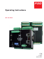
Operating Instructions
ETR 132 PNIO
Rev. 1.00.01
08/2015
Translation of original
operating instructions
1
PSG Plastic Service GmbH
Bedienungsanleitung ETR132PNIO
Introduction
3
Typographical Conventions
Additional and continuative documents
4
4
General Information
5
Warranty Conditions
Installation and safety references
5
5
Equipment Implementation
7
Type designation
Type plate
Scope of supply
Accessories
7
8
8
8
Device construction
9
Dimensions
Connection overview
Status LED‘s
DIP switch
9
9
9
10
Installation/Dismantling
11
Electrical connection and operational startup
12
Connection type
Connector assignment and basic configuration
Power supply (Connection X11)
Auxiliary voltage (Connection X7)
Measurement inputs (Connection X5 to X6)
Measurement inputs of type designation TPDK
Control Outputs (Connection X1, X2)
Digital inputs (Connection X7)
Digital outputs (Connection X7)
Heating Current Inputs (connection X3, X4)
CAN-Bus (Connection X10)
TCP & PNIO interface (connection X14, X15)
12
13
13
13
14
15
17
19
20
21
23
24
Addressing and Further Functions by DIP Switch
25
Status displays/Diagnostics
27
Information 'zone text'
Overview of zone texts
System error
Summary of system errors / flashing codes OK-LED
Status indication TCP/PNIO LED‘s
Diagnostic function (code number 600) - Allocation of Sensor and Heating
Diagnostic function (Code Number 601) - Start Current Measurement
Manual Activation of a Current Measurement (Code Number 41)
27
28
29
31
31
32
33
33
Rev. 1.00.01
Technische Änderungen vorbehalten
2
Configuration and Settings
Basic configuration
Configuration inputs
Configuration/Functions Outputs
Basic Functions
Setpoint Value Functions
Control characteristic
Alarm management
Heating Current Monitoring
Group functions
CAN-BUS
Ethernet
Change IP setting
Gateway
Representation of operating/visual display units BA
Other parameters
Tabular overview
Parameters
System- and communication parameters
34
34
35
41
42
46
49
57
62
65
66
67
68
68
69
69
71
71
73
Code numbers
75
Firmware update
77
Appendix
78
Version History
Rev. 1.00.01
Technische Änderungen vorbehalten
78
PSG Plastic Service GmbH
Operating instructions ETR132PNIO
1
Introduction
Building on a common platform, the temperature control system sysTemp® PNIO offers different concepts for customized multi-zone temperature control.
The common platform of sysTemp® PNIO guarantees continuity with the configuration and parameterization, as
well as with the connection over the available digital interfaces. On each controller the interfaces CAN bus, PROFINET IO and Ethernet are available.
The powerful and universal temperature controller ETR132PNIO is designed for employment in hot runner applications, machines for the plastics processing, packaging machines, furnaces, foodstuffs processing, dryers, etc.
With its adaptive parameter matching, it can be used in a wide field of application from extremely fast to extremely
slow zones.
The ETR132PNIO is modular built and consists of a basic module and up to three expansion modules for up to 32
three-position zones.
32 Measurement inputs
64 Control outputs
32 Heating Current In-
puts
3 Alarm outputs
2 Digital inputs
CAN-BUS
PROFINET IO
ETHERNET
The device is available in different implementations. This must be considered at installation and operational startup. You find more detailed references to that in the chapter Equipment Implementation and Electrical connection and operational startup.
These directions assist, both in case of the initial installation and operational startup of the device, and in case of
changes and adaptations to existing control systems. Status and error messages are described and remedies are
recommended for elimination of faults.
The protocol descriptions for CAN-Bus, PROFINET IO and Ethernet are not a component part of the operating
manual. You are provided with these on request or directly as a download from the home page of PSG Plastic
Service GmbH (www.psg-online.de).
Rev. 1.00.01
Technical changes reserved
3
4
Chapter 1
Introduction
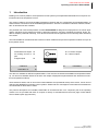
1.1 Typographical Conventions
Symbols and conventions are used in this manual for faster orientation for you.
Symbols
Caution
With this symbol, references and information are displayed which are decisive for the operation of the device. In case of non-compliance with or inaccurate compliance there can
result damage to the device or injuries to persons.
Note
The symbol refers to additional information and declarations, which serve for improved
understanding.
Example
With the symbol, a function is explained by means of an example.
Reference
With this symbol, information in another document is referred to.
Cross references are marked with this character. In the pdf version of the document the
objective of the cross reference is reached via the link.
Equations
Calculation specifications and examples are represented in this way.
n.a.
Not applicable, not existing
1.2 Additional and continuative documents
Protocol
PSG II Ethernet
Information on this topic are in the protocol description PSG II Ethernet and
the corresponding object lists.
Protocol
PROFINET IO
Information on this topic are in the corresponding object lists PROFINET IO.
Protocol
CANopen
Information on this topic are in the protocol description CANopen and the corresponding object lists.
Data sheets and operating manuals
Available by Internet see www.psg-online.de
Rev. 1.00.01
Technical changes reserved
PSG Plastic Service GmbH
Operating instructions ETR132PNIO
2
General Information
2.1 Warranty Conditions
This product is subject to the legal warranty time periods for faults or deficiencies in manufacture.
Content of Warranty
If a malfunction relatively occurs through the manufacture, PSG Plastic Service GmbH repairs or replaces the nonconforming product, according to their own discretion.
The following repairs do not fall under the warranty and are liable to costs:
Malfunctions after the legal notice periods have expired.
Malfunctions caused through operating error of the user (if the device is not operated as described in the manual).
Malfunctions caused through other devices.
Changes or damage to the device which do not originate from the manufacturer.
If you wish to use services within the framework of this guarantee, please refer to PSG Plastic Service GmbH.
2.2 Installation and safety references
Before installation, handling or operation of the device, please read through this operating instructions
completely and carefully.
This device corresponds to the European Directives for Safety and EMC. It is within the sphere of responsibility of the commissioning engineer to keep to these directives during the installation of the device.
Standards
EN 61000-6-4, EN 61000-6-2, EN 61326-1
CE marking
The device complies with the European Directives for electromagnetic compatibility (complies with EN 61326-1).
Service and repair
This device is maintenance free.
If the device should indicate a fault, please contact the manufacturer. Customer repairs are not permissible.
Cleaning
Employ no water or cleaning agents based on water for the cleaning of the device stick-on labels. You can clean
the surface of the devices with a mild soap solution.
Storage
If you should not put the device into operation immediately after unpacking, protect it against moisture and coarse
dirt.
Personnel
The installation of the device may by carried out by qualified personnel only.
Wiring
The wiring system must be implemented correctly according to the specifications in this operating manual. All
feeds and connecting terminals must be dimensioned for the corresponding amperage. Furthermore, all connections are to be carried out according to the valid VDE Specification and/or the respective national specifications.
Ensure in particular that the AC power supply is not connected with the logic output or the low-voltage
input.
Rev. 1.00.01
Technical changes reserved
5
6
Chapter 2
General Information
Overload protection
Secure the power supply of the device and the relay output with a fuse protection or a power circuit-breaker. This
protects the printed circuit boards against overcurrent.
Environment
Conducting contamination must not reach the proximity of the device connecting terminals in the control cabinet.
In order to achieve suitable ambient air conditions, install an air filter in the air inlet of the control cabinet. If the
device should be in a condensing environment (low temperatures), install a thermostat-controlled heating unit in
the control cabinet.
Rev. 1.00.01
Technical changes reserved
PSG Plastic Service GmbH
Operating instructions ETR132PNIO
3
Equipment Implementation
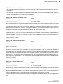
3.1 Type designation
The equipment of the device, over and beyond the standard type, is stipulated with the order. The exact specification can be read off on the Type plate type designation plate, which is on the carton, the casing and the printed
circuit board.
The type designation identifies the equipment version and is composed of the options.
ETR132PNIO
Module variant
G
Base module
Electrical connections
K
FZ
Screw terminal
Spring terminal
Control output
HO
Heating
Control output
KO
Not existing
Cooling
Measurement inputs
TCPt
U
I
Not existing
Thermocouple TC/ resistance thermometer Pt100
Standard signal U 0/2...10V
Standard signal I 0/4...20mA
Heating current recording
STI
Not existing
Heating current recording
Data interface
(only base module)
CAN
CAN-Bus with CANopen-conform connector pin assignment
Voltage
24 V
20...30 VDC
Rev. 1.00.01
Technical changes reserved
7
8
Chapter 3
Equipment Implementation
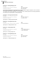
3.1.1 Type plate
The following information can be taken from the type plate:
PSG/D-68309 Mannheim
ETR 132 PNIO
K HO KO TC/PT
CAN OPEN/Profinet/24VDC
HW0000002) SW805143)
ANr. ******4)
SNr. **********5)
1 Type designation
2 Revision identification of the printed circuit boards
3 Revision identification of the controller software
4 Order number
5 Serial number
To identify a device in a computer network clearly, a MAC address (Media Access Control address) will be given.
The MAC addresses can be read on the label.
3.2 Scope of supply
1 Temperature control system ETR132PNIO
1 CD-ROM with full documentation and software
3.3 Accessories
For information on the extensive accessories please refer to the homepage www.psg-online.de.
Rev. 1.00.01
Technical changes reserved
PSG Plastic Service GmbH
Operating instructions ETR132PNIO
4
Device construction
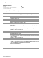
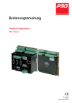
4.1 Dimensions
125 mm
The modules ETR132PNIO G and ETR132 E have has a
securing mechanism for the installation on DIN rail (DIN
50022) see Installation/Dismantling.
The height and width specifications apply for both modules. ETR132 E is 30 mm deep.
155 mm
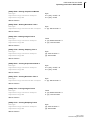
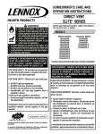
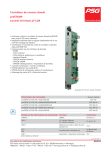
4.2 Connection overview
The connection overview here indicates all possible connection variants.
The actual connection overview depends on the Equipment Implementation which is stipulated with the order.
ETR132PNIO G and ETR132 E
X1
X3
X2
X4
X1
X3
X2
X4
C
B
A
X5
X6
X5
X6
X1
Control outputs heating 1...8
X2
Control outputs Cooling 1...8
X3/X4
Heating current monitoring 1...8
X5
Measurement inputs 1...4
X6
Measurement inputs 5...8
X7
Alarm outputs 1...3,
Digital inputs 1...2
X10
CAN interface
X11
Power supply
X14
TCP/PNIO interface PROFINET IO
X15
TCP/PNIO interface PROFINET IO
A
Status-LED‘s
B
DIP switch
C
Status-LED‘s TCP/PNIO
4.2.1 Status LED‘s
The SIO-LED (yellow) signalizes the interface operation and flashes quicker or slower due to the amount of data.
In the normal case the OK-LED (green) on the front panel of the controller lights up permanently.
Rev. 1.00.01
Technical changes reserved
9
10
Chapter 4
Device construction
The OK-LED flashes if there is a fault. The cause of error can be read off on the basis of the number of flashing
signals. Detailed information about the error cause can be referred to in the chapter System errorand Summary
of system errors / flashing codes OK-LED
See also Status indication TCP/PNIO LED‘s.
4.2.2 DIP switch
Detailed information on the function of the DIP switches are in the chapter Addressing and Further Functions by
DIP Switch
Rev. 1.00.01
Technical changes reserved
PSG Plastic Service GmbH
Operating instructions ETR132PNIO
5
Installation/Dismantling
ESD Avoidance
To avoid ESD damages the device must be handled, packed,
unpacked and stored in an especially protected environment
(Electrostatic Protected Area, EPA). An ESD-protected work
environment conducts existing electrostatic charges to ground in a
controlled manner and prevents their re-occurrence.
Unpacking
The device is packed fully-mounted in a robust carton, cushioned with
foamed material.
Check the packaging and then the device for identifiable damage incurred during transit. If damage is identified, then please get in touch
with the transportation company.
In the case of damage the device may not be brought into operation.
Ensuring voltage-free state
Before beginning and during all installation/dismantling work,
attention is to be paid that the system, as well as the devices,
are de-energized
Installation location
A device of the protection type IP20 is to be installed in a closed control
cabinet.
Securing
The device has a securing mechanism for installation on a DIN rail
(DIN 50022).
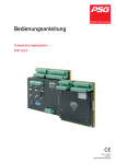
Installation/Dismantling
The device is initially suspended in the DIN rail with the two straps
(rear/middle side) and then latched in. For dismantling, the unlocking
mechanism on the front below at the device (Illustration) is to be
screwed down with a screwdriver and the device taken out towards the
front/above.
Device exchange
Only controllers of the same type should be exchanged. In
case of replacement, it is absolutely necessary to adopt the
setting adjustments of the replaced controller.
Rev. 1.00.01
Technical changes reserved
11
12
Chapter 6
Electrical connection and operational startup
6
Electrical connection and operational startup
The ETR132PNIO may be installed and put into operation by specialist personnel only.
Before switch-on of the control zones it is to be ensured that the ETR132PNIO is configured for the
application. An incorrect configuration can lead to damage to the control section or to injuries to persons.
6.1 Connection type
In the standard type the device is equipped with screwed terminals. The terminals existing on the device are to be
taken from the Type designation
The following plugs of the Co. Phoenix are employed for the individual connections:
Connection
ETR132PNIO
Type designation
Plug for screwed terminal
Type designation
OPTION Plug for spring terminal
X1...X2
MCVR 1.5/10-STF-3.81
FK-MCP 1.5/10-STF-3.81
X3...X4
MCVR 1.5/14-STF-3.81
FK-MCP 1.5/14-STF-3.81
X5...X6
MCVR 1.5/10-STF-3.81
FK-MCP 1.5/10-STF-3.81
X7
MCVR 1.5/10-STF-3.81
FK-MCP 1.5/10-STF-3.81
X11
MVSTBW 2.5 HC/3-STF-5.08
FKC 2.5 HC/3-STF-5.08
The wiring system is implemented on the screwed terminals and spring terminals with the appropriate cable lugs.
Cables with a cross section of 0.5 to 1.5mm2 can be employed.
Rev. 1.00.01
Technical changes reserved
PSG Plastic Service GmbH
Operating instructions ETR132PNIO
6.2 Connector assignment and basic configuration
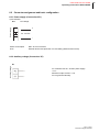
6.2.1 Power supply (Connection X11)
3 pole terminal
Power supply
X11
DC voltage
+
+
20...30 VDC
-
-
Power consumption
Max. 25 VA on full load
Fuse
External device fuse protection 4 A time-delay (without load on X7/8)
6.2.2 Auxiliary voltage (Connection X7)
Auxiliary voltage
X7
For controller with 20...30 VDC power supply:
-0.7 V
Maximum output current: 1.5 A
Do not ground externally!
Rev. 1.00.01
Technical changes reserved
13
Chapter 6
Electrical connection and operational startup
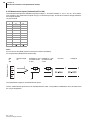
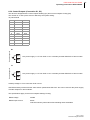
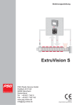
6.2.3 Measurement inputs (Connection X5 to X6)
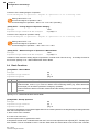
The measurement inputs are stipulated in groups of eight (1...8 on basic module; 9...16, 17...24, 25...32 on expansion modules). The measurement inputs occupy 2 connections per input, 0V has to be used for all eight measurement inputs together.
10 pole terminal
PIN
X5
X6
1
1+
5+
2
1-
5
3
2+
6+
4
2-
6-
5
3+
7+
6
3-
7-
7
4+
8+
8
4-
8-
9
0V*
0V*
10
Note *
Do not connect 0V (GND) system overall (over several controllers)!
Do not ground 0V (GND)-terminal externally!
X5
to
X6
Thermocouple
TC
Resistance ther- Resistance thermometer Pt100 mometer Pt100
3-wire
2-wire
Current I
Voltage U
Measurement input
14
The specifications apply for all measurement inputs.
The the measurement inputs are to be indicated with the order. The possible combinations are to be taken from
the Type designation.
Rev. 1.00.01
Technical changes reserved
PSG Plastic Service GmbH
Operating instructions ETR132PNIO
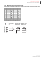
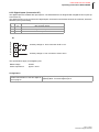
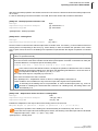
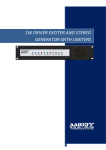
6.2.3.1 Measurement inputs of type designation TPDK
For devices with type designation TPDK (TC/Pt100, double level terminal) each measurement input has a separate HF ground and/or 0V terminal.
PIN
X5
X5
X6
X6
1
1+
1
5+
5
2
1-
3
2+
4
2-
5
3+
6
3-
7
4+
8
4-
8-
9
0V
0V
52
6+
6
63
7+
7
74
8+
8
10
Thermocouple
TC
Resistance ther- Resistance thermometer Pt100 mometer Pt100
3-wire
2-wire
Measurement input
X5
to
X6
Rev. 1.00.01
Technical changes reserved
15
16
Chapter 6
Electrical connection and operational startup
Configuration
Arrange sensor type for the measurement [SP18] SEN1 - Sensor type Zone 1...8
inputs.
[SP19] SEN2 - Sensor type Zone 9...16
[SP20] SEN3 - Sensor type Zone 17...24
[SP21] SEN4 - Sensor type Zone 25...32
Stipulate offset valid for all zones.
[P033] OFFS - Temperature Offset
Stipulate offset valid for the corresponding [SP28] OFF1 - Offset Zone 1...8
zones.
[SP29] OFF2 - Offset Zone 9...16
[SP30] OFF3 - Offset Zone 17...24
[SP31] OFF4 - Offset Zone 25...32
Stipulation of the measuring range, when [P047] RG L - Lower Temperature Value at Standard Signal Inmeasurement input is of the standard signal puts
type.
[P048] RG H - Upper Temperature Value with Standard Signal Inputs
Stipulate units of all measured values.
[SP22] CELS – Temperature Unit °C/°F
Specification of the measuring channel, if [P057] NoZN - Zone Allocation to Measurement Input on Sensor
measured value comes from a FIN 08 or Interface FIN
CANAIN08 over CAN-Bus.
Rev. 1.00.01
Technical changes reserved
PSG Plastic Service GmbH
Operating instructions ETR132PNIO
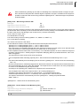
6.2.4 Control Outputs (Connection X1, X2)
The device is designed with 8 control outputs Heating (X1) and 8 control outputs Cooling (X2).
The number of 3- and 2-point zones is defined by the system setting.
10 pole terminal
PIN
X1
X2
1
UH1
UC1
2
UH2
UC2
3
OH1
OC1
4
OH2
OC2
5
OH3
OC3
6
OH4
OC4
7
OH5
OC5
8
OH6
OC6
9
OH7
OC7
10
OH8
OC8
Control output H
X1
UH1 power supply -0.7 V from X7/8 or Uext or auxiliary terminal UH2/UC2 of other module.
Control output K
X2
UH1 power supply -0.7 V from X7/8 or Uext or auxiliary terminal UH2/UC2 of other module.
Auxiliary voltage U- from connection X7/9 or 0Vext.
UH2/UC2 auxiliary terminal has the same electric potential like UH1/UC1 and can be used for the power supply
of further outputs on other modules.
The specifications apply for all control outputs Heating/ Cooling.
Rated voltage
30VDC
Rated output current
60mA
Inductive load only with external free-wheeling diode switchable
Rev. 1.00.01
Technical changes reserved
17
18
Chapter 6
Electrical connection and operational startup
Configuration
Define the operating mode of the control [P038] COOL - 3-Point Operation
zone.
Stipulates the manner in which the actuat- [P039] RELH – Heating Relay Output
ing signal is output at the control output.
[P040] RELC – Cooling Relay Output
Is the cooling output used as alarm output, [P043] ALC1 - Cooling Alarm Output 1
stipulate which alarm is output on the cool- [P044] ALC2 - Cooling Alarm Output 2
ing output.
Rev. 1.00.01
Technical changes reserved
PSG Plastic Service GmbH
Operating instructions ETR132PNIO
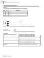
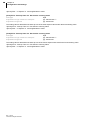
6.2.5 Digital inputs (Connection X7)
The digital inputs are realized with optocouplers. The standard device is designed with 2 digital function inputs (at
Connection X7) .
The digital function inputs, as well as the digital inputs, work with functions fixed stored in the controller, which are
defined by the system setting.
PIN
X7
Description
1
I2
Dig. function input 2
2
I1
Dig. function input 1
3
I-
Reference potential I *
Dig. function input
X7
Auxiliary voltage U+ from connection X7/8 or Uext
Auxiliary voltage U- from connection X7/9 or 0Vext
The specifications apply for all digital inputs.
Rated voltage
30VDC
Power requirement
approx. 12mA
Configuration
Stipulate function which is implemented on [SP23] INP1 - Function Digital Input 1
activation/deactivation of the two digital in- [SP24] INP2 - Function Digital Input 2
puts on plug X7.
Rev. 1.00.01
Technical changes reserved
19
Chapter 6
Electrical connection and operational startup
6.2.6 Digital outputs (Connection X7)
The digital outputs are realized with optocouplers. The standard device is designed with 3 alarm outputs (at connection X7) .
In the system setting it is defined which alarms are output on the outputs .
PIN
X7
Description
4
AL3
Alarm output 3
5
AL2
Alarm output 2
6
AL1
Alarm output 1
7
AL+
Supply voltage for alarm outputs
X7
Alarm output
20
Auxiliary voltage U+ from X7/8 or Uext
Auxiliary voltage U- from connection X7/9 or 0Vext. The specifications apply for all digital outputs.
Rated voltage
30VDC
Rated output current
60mA
Inductive load only with external free-wheeling diode switchable
Configuration
Stipulate function of the alarm output 1.
[SP08] A1D1 - Definition Byte 1 - Alarm Output 1
[SP09] A1D2 - Definition Byte 2 - Alarm Output 1
[SP10] A1D3 - Definition Byte 3 - Alarm Output 1
Stipulate function of the alarm output 2.
[SP11] A2D1 - Definition Byte 1 - Alarm Output 2
[SP12] A2D2 - Definition Byte 2 - Alarm Output 2
[SP13] A2D3 - Definition Byte 3 - Alarm Output 2
Stipulate function of the alarm output 3.
[SP14] A3D1 - Definition Byte 1 - Alarm Output 3
[SP15] A3D2 - Definition Byte 2 - Alarm Output 3
[SP15] A3D2 - Definition Byte 2 - Alarm Output 3
Stipulate which alarms are calculated if zone is [P051] ALP1 - Alarm Calculation 1 with Passive Zones
passivated.
[P052] ALP2 - Alarm Calculation 2 with Passive Zones
Rev. 1.00.01
Technical changes reserved
PSG Plastic Service GmbH
Operating instructions ETR132PNIO
6.2.7 Heating Current Inputs (connection X3, X4)
The standard device is designed for registration of 3-phase heating currents per zone (individual current measurement) or summation current measurement.
In the system setting the measurement method is stipulated.
Use the current transformers available as accessories by PSG Plastic Service GmbH.
14 pole terminal
PIN
X3
X4
1
C11
C51
2
C12
C52
3
C13
C53
4
C21
C61
5
C22
C62
6
C23
C63
7
C31
C71
8
C32
C72
9
C33
C73
10
C41
C81
11
C42
C82
12
C43
C83
13
C0V*
C0V*
14
Individual current measurement
the heating current inputs are tightly allocated to zones (C1* to zone 1, C2* to zone 2, etc.)
for 1-phase current measurement do not connect the terminals for the second and third phase of one zone
Summation current measurement
the heating current inputs are allocated to zones by [P056] NoTR - Allocation Current Transformer
Heating current input
X3 and X4
Note *
Do not connect C0V system overall!
Do not ground C0V terminal!
Using the supply voltage measurement module SUW the system parameter
SUW defines, on which current measurement input the SUW module is connected.
The specifications apply for all heating current inputs.
Input
Input voltage configurable (standard 42 mV/A)
Input resistance
20kOhm
Rev. 1.00.01
Technical changes reserved
21
22
Chapter 6
Electrical connection and operational startup
Configuration
Specify method of measurement of heating cur- [SP25] AMPD – Heating Current Measurement Method
rent.
Comparative value for the heating current of the [P011] AMPN - Current Setpoint Value
measured zone.
Stipulate tolerance value for control of heating cur- [P010] AMPT - Current Tolerance
rent value.
Stipulate the measurement input where the current [P056] NoTR - Allocation Current Transformer
transformer of the controlled zone is connected to.
Stipulate the scale of the measurement input.
[Zone 046] AMPE - Current Range End Value
Stipulate the value of the heating current that rises [SP34] AMPM - Maximum Current Value with Measurean alarm in case of switched-off heating.
ment Heater Off
Rev. 1.00.01
Technical changes reserved
PSG Plastic Service GmbH
Operating instructions ETR132PNIO
6.2.8 CAN-Bus (Connection X10)
D-SUB, plug
PIN
X10
CANopen
1
n.a.
2
CAN-L
3
n.a.
4
n.a.
5
n.a.
6
n.a.
7
CAN-H
8
n.a.
9
n.a.
The communication over the CAN-Bus uses the protocol CANopen. You are provided with an object
list (zone and system parameters which are stored for the controller type in the protocol) of the device,
as a download, on request, or directly from the homepage PSG Plastic Service GmbH (www.psg-online.de).
Configuration
The configuration of the communication over the CAN-Bus interface is implemented with the aid of the parameters
listed under CAN-BUS.
Rev. 1.00.01
Technical changes reserved
23
24
Chapter 6
Electrical connection and operational startup
6.2.9 TCP & PNIO interface (connection X14, X15)
RJ45, Socket
PNIO PROFINET IO
TCP/IP
PIN
X14
X15
1
TD+
TD+
2
TD-
TD-
3
RD+
RD+
4
Termination
Termination
5
Termination
Termination
6
RD-
RD-
7
Termination
Termination
8
Termination
Termination
X14
X15
Standard definition,
automatic Cross-over
The communication over the PROFINET IO interface uses the protocol PROFINET IO. You are provided with an object list (zone and system parameters which are stored for the controller type in the protocol) of the device, as a download, on request, or directly from the homepage PSG Plastic Service
GmbH (www.psg-onli-ne.de).
Rev. 1.00.01
Technical changes reserved
PSG Plastic Service GmbH
Operating instructions ETR132PNIO
7
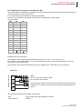
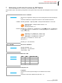
Addressing and Further Functions by DIP Switch
Using the DIP switch, the following configuration of the system and functions like acknowledgement can be carried
out.
DIP 1...4
Device ID - NodeID/IP
ON
1 2 3 4 5 6 7 8
Device ID is enciphered in binary form and is set adjusted over the DIP switches
1...4.
The device address is composed as follows for the individual interfaces:
CANBus Resulting NodeID = [SP05] CADR - CANopen Base Address + Device ID
[SP05] CADR - CANopen Base Address = 32
Device ID = 2
Resulting NodeID = 34
Ethernet Resulting IP = [SP46) IP1 - IP Address of 1. Octet.[SP47] IP2 - IP Address of
2. Octet.[SP48] IP3 - IP Address of 3. Octet.([SP49] IP4 - IP Address of 4.
Octet + Device ID)
[SP46) IP1 - IP Address of 1. Octet = 192
[SP47] IP2 - IP Address of 2. Octet = 168
[SP48] IP3 - IP Address of 3. Octet = 0
[SP49] IP4 - IP Address of 4. Octet = 200
Device ID = 2
Resulting IP = 198.168.0.202
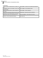
DIP 1...4 & DIP7
ON
1 2 3 4 5 6 7 8
DIP 5...6
Device ID = DEFAULT
Resulting NodeID = 32
Resulting IP = 192.168.0.200
! Only if DIP7 = ON
Baud rate CAN
ON
1 2 3 4 5 6 7 8
DIP7
DIP5
DIP6
Baud rate CAN
OFF
OFF
PSG (78.8 kBit)
ON
OFF
250 kBit
OFF
ON
500 kBit
ON
ON
125 kBit
IP dynamic/ fix
ON
1 2 3 4 5 6 7 8
0 dynamic
The superior control system assigns an IP address to the device.
1 fix
The device uses the IP address set (see DIP 1...4).
Rev. 1.00.01
Technical changes reserved
25
26
Chapter 7
Addressing and Further Functions by DIP Switch
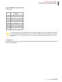
DIP 1...7
Take Over of Switch-On Configuration
5 sec
ON
1 2 3 4 5 6 7 8
DIP8
On the base module DIP switch 1...7 must be set to ON for at least 5 seconds.
This signalizes the system to take the new configuration, when the number of
expansion units has changed.
CANBus termination
ON
DIP8 ON activates the internal CANBus termination impedance of 120 Ohm.
1 2 3 4 5 6 7 8
DIP 1...8
ON
1 2 3 4 5 6 7 8
.
Rev. 1.00.01
Technical changes reserved
Acknowledge error report
By setting all 8 DIP switches to ON and thereafter to the pervious setting, the acknowledgement of pending error messages is initiated.
PSG Plastic Service GmbH
Operating instructions ETR132PNIO
8
Status displays/Diagnostics
8.1 Information 'zone text'
In case of certain operational states of the controller, a text is overlaid alternately with the actual value in the zone
display of the operating and display units. This text can be read out under the byte ZoneFMode for every zone
over all interfaces. The information is also designated as a zone text.
Since only the zone text with the highest priority can always be displayed, the zone text is to be considered exclusively as an extension to the status information of a zone. The byte ZoneFMode includes the following information:
Bit
on
off
0...5
Zone text (Overview of zone texts)
6
Zone has correct model of the zone. At least a Zone does not have any correct model of the zone.
[P035] IDEN - Heating Identification has been No [P035] IDEN - Heating Identification has yet
successfully carried out.
been successfully carried out.
7
Zone active.
Zone passive.
Rev. 1.00.01
Technical changes reserved
27
28
Chapter 8
Status displays/Diagnostics
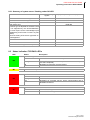
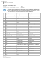
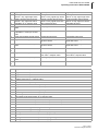
8.1.1 Overview of zone texts
Signal
flag
(dec)
Display Meaning
1
Ma
Manual mode
x
2
CoU
Leading zone manual mode
x
3
AbS
Reduction
x
4
rAP
Temperature ramp
x
5
StA
Start-up operation
x
6
Alarm Status
Without function
7
Id
Identification
x
8
IdC
Cooling adaptation
x
9
tCb
Sensor break
x
10
FAL
Sensor short-circuit
x
11
tcP
Sensor incorrect polarity
x
12
CAn
Fault in CAN communication
x
13
Err
System error/ fault in channel data
x
14
AL
Exceeded maximum temperature/ upper limit of measuring range
x
15
PId
Plausibility violation during the identification
x
16
drl
Drift error report during identification phase
x
17
IF
Error report "No heating current measured" during identification phase
18
SP2
2.setpoint value
x
19
SP3
3.setpoint value
x
20
SP4
4.setpoint value
x
21
dF1
Fault "No current" determined in case of "Heating current" diagnostics
22
dF2
Fault "Current on incorrect zone" determined in case of "Heating current"
diagnostics
x
23
dF3
Fault "Current both on correct as well as on another zone" determined with
"Heating current" diagnostics
x
24
dE
No fault determined with "Heating current" diagnostics / "Allocation sensor/
heating" diagnostics ends
x
25
dIA
Diagnostics function active
x
26
dF4
Fault "Alarm current with switched off heating" determined in case of diagnostics
x
27
Ar
Automatic ramp
x
28
Ar.
Automatic ramp active, zone with least temperature rise
x
29
I-
Alarm "Current alarm with heating off"
x
30
ALS
Storing alarm function
x
31
IdS
Automatic cooling adaptation started, however still not active
x
32
GP
Zone waits for group release
x
33
x
x
n.a.
34
000
35
001
Error signal
x
36
002
Module matching system error
x
37
003
CPU calibration error
x
38
004
Rev. 1.00.01
Technical changes reserved
PSG Plastic Service GmbH
Operating instructions ETR132PNIO
Signal
flag
(dec)
Display Meaning
39
005
40
006
41
007
42
43
Alarm Status
Error in system data
x
008
Switch-on configuration
x
009
Switch-on configuration sensor
x
44-49
n.a.
50
Out
Power controller disconnected (Digital Input 2 active and system parameter
INPD equal to 0 or 1)
x
51
CuI
CAN error in data link controller/CANSTI
x
52
ArE
Automatic ramp fault
x
53
ArE.
Automatic ramp fault, zone with least rate of rise
x
54
GPO
Bypass group release
x
55
GPA
Reduce group release
x
8.2 System error
Unlike zone-specific faults (temperature limit values, heating current alarms, etc.) system errors identify faults on
the controller itself. The system errors can be read out from the controller on the zone flags over all interfaces.
Detailed information on this can be found in the object lists for the corresponding protocols.
The cause of error, the output of the OK-LED on the controller, the message text in the operating and display units,
as well as notes on the elimination of the fault, are indicated below for all possible system errors.
Fault in the CPU basic matching
If the basic matching of the controller cannot be read correctly any longer, then the bit "Fault in the basic matching"
is set.
On all zones of the controller a degree of operation of 0% is output.
On the OK-LED of the controller a flashing signal is output.
With the operating and display units, ERR 003 is displayed.
For the removal of the fault, the controller is to be set to the ex-works state (Code Number 759). Before resetting
into the ex-works state, please note down all channel data and system dates or read out and store with project
setup and configuration tool.
Fault in the module matching
The module matching data items are stored on every module . If these cannot be read correctly any longer, then
the bit "Fault in the module matching" is set.
On all zones of the module, a degree of operation of 0% is output
If a "fault in the module matching" is identified for the zones, then two flashing signals are output at the OK-LED
of the controller.
With the operating and display units, ERR 002 is displayed.
No possibility exists to eliminate the error report. The controller must be sent in for repair.
Fault in channel data
For the assurance of the data consistency and the data security, a checksum is stored for every zone in case of
storage of the configuration data into the EEPROM.
The bit „Fault in channel data“ is activated, when the controller detects a check sum error during reading of channel
data.
If a "Fault in channel data" is identified, seven flashing signals are output on the OK-LED.
With the operating and display units, ERR is displayed in the zone display.
Rev. 1.00.01
Technical changes reserved
29
30
Chapter 8
Status displays/Diagnostics
For the removal of the fault, all zone-specific configuration parameters are to be checked, a value changed and
the change stored in the EEPROM. After this, wait 20 seconds and carry out a controller reset. After the controller
restart, the fault should have disappeared.
If the fault reappears after the reset, then there is a hardware fault in the EEPROM. The controller must be sent
in for repair.
Fault in System data/ Attributes
The system data is stored grid-failure-secure in the EEPROM of the controller. The bit "Fault in system data/attributes" is set if data change without external intervention.
On all zones of the controller a degree of operation of 0% is output.
If a "Fault in system data/attributes" is identified, then six flashing signals are output on the OK-LED.
With the operating and display units, ERR 005 is displayed.
For the removal of the fault, all system data and attributes are to be checked, a value changed and the changes
taken over into the EEPROM. After this, wait 20 seconds and carry out a controller reset (e.g. over code number
999). After the controller restart, the fault should have disappeared.
If the fault reappears after the reset, then there is a hardware fault in the EEPROM. The controller must be sent
in for repair.
CAN-Bus fault
A fault CAN-Bus occurs, for example, when data which should be received by the controller over CAN-Bus controller (e.g. measured values of FIN 08 or CANAIN 08) does not reach the controller or CAN components corresponding to the controller cannot be identified by the controller.
In case of a fault on the CAN-Bus, eight flashing signals are output on the OK-LED.
In case of the operating and display units, CAN is displayed in the zone displays.
For elimination of the fault all cable connections, settings of CAN baud rate, address settings have to be checked.
Error PROFINET-Chip (TPS1) not correctly started
If the PROFINETIO Chip does not start, a communication with the controller is not possible.
If a "Fault PROFINET IO Chip" is identified, nine flashing signals are output on the OK-LED.
For elimination of the fault execute a controller reset. After the controller restart, the fault should have disappeared.
If the fault reappears after the reset, then there is a hardware fault in the EEPROM. The controller must be sent
in for repair.
Rev. 1.00.01
Technical changes reserved
PSG Plastic Service GmbH
Operating instructions ETR132PNIO
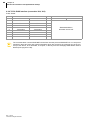
8.2.1 Summary of system errors / flashing codes OK-LED
Cause of error
Number of flashing
signals
Display of operating and display units
Fault in the CPU basic matching
1
ERR 003
Fault in the module matching
2
ERR 002
Fault in System data/ Attributes
6
ERR 005
ERR 009
Fault sensor type
(A sensor type is adjusted for the device, that
is not supported by the device/calibration.
The error report can be acknowledged (see
Addressing and Further Functions by DIP
Switch).
Check the setting of the sensor type after acknowledgement.
Error in channel data
7
ERR
CAN-Bus fault
8
CAN
Error PROFINET-Chip (not correctly started)
9
8.3 Status indication TCP/PNIO LED‘s
LED
Status
Description
Device Ready
DR
MT
OFF
PROFINET IO Interface not correctly started
flashing
PROFINET IO Interface waits for synchronization with CPU (firmware start completed)
ON
PROFINET IO Interface correctly started
Maintenance Required
Bus Failure
BF
ON
No Link-Status available
flashing
Link-Status OK; no communication link to PROFINET IO controller
OFF
PROFINET IO controller has an active communication link to
PROFINET IO device
System Failure
SF
ON
PROFINET IO Diagnostics available
OFF
No PROFINET IO Diagnostics
Rev. 1.00.01
Technical changes reserved
31
32
Chapter 8
Status displays/Diagnostics
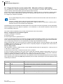
8.4 Diagnostic function (code number 600) - Allocation of Sensor and Heating
The controller has a complex automated function to check the allocation of sensors and Heating. The function
checks, whether sensors and Heating are allocated and wired correctly.
The function uses the configuration parameter [P032] STT4 - Start-up Time of 4. Set Point/4. Lowering Value.
By this, a zone specific testing period is specified. The testing period defines the time, the zone should react
on a trigger by the degree of operation.
For an optimal diagnostic process, the diagnostic function should be executed, when the zones are in
cold condition.
Specify a setpoint value for the zone that is smaller than the actual value
Check the configuration parameter [P032] STT4 - Start-up Time of 4. Set Point/4. Lowering Value
Passive zones are not included in the diagnostics
The diagnostic function is basically executed until the end, even when errors are recognized. It is only interrupted,
when a temperature rise for a degree of operation = 0% is detected, i.e. the actuator is defective, what can lead
to an overheating of the zone.
The check routine is started by entry of code number 600 and runs in two phases.
Phase 1: Complete Check of all Zones together
In phase 1 the degree of operation
of all active zones,
whose setpoint value is greater than 0°C
is set to 0% and all actual value are monitored. Using the operating and display unit BA, in the zone display of the
zones, relevant for diagnostic process, the message dIA is output. The zone display for the other zones is dimmed.
The corresponding information can be requested by message flag ZoneFMode by interface.
Rises the actual value of any zone at least 5°C in between the testing period, in the zone display for this zone dE
and 888 is displayed alternately and the check routine is completely stopped. The stopped check routine must be
acknowledged by code number 602.
Phase 2: Single Check
After termination of phase 1 (takes as long, as the maximal specified value for [P032] STT4 - Start-up Time of
4. Set Point/4. Lowering Value)
a single check of each zone, consecutive for each zone, is started.
For this, the degree of operation of one zone is set to 100% and monitored, whether a temperature rise of 5°C in
between the specified testing period [P032] STT4 - Start-up Time of 4. Set Point/4. Lowering Value is detected.
Using the operating and display unit BA, in the zone display the message dIA is output.
After termination of the single check for all zones, the diagnostic result is immediately displayed in the zone display
for the relevant zones. Alternately dE (DiagnosticResult) and a number are displayed, where the diagnostic result
could easily be deduced.
Message BA at Diagnostic End
Meaning
dE
0
Zone OK
dE
1_32
The sensor to this zone is wrongly connected to channel x
dE
- 1_-32
The sensor to this zone is wrongly connected to channel x and with reversed polarity
dE
999
Sensor break
dE
888
Temperature rise in spite of degree of operation 0%
dE
≡ 777
No temperature rise during diagnostic period detected
Rev. 1.00.01
Technical changes reserved
PSG Plastic Service GmbH
Operating instructions ETR132PNIO
The status of diagnostics of the zone can be requested by message flag ZoneFMode (for PSGII protocol offset
0x60).
Value of message flag ZoneFMode active = 25(dec)
[1…5]
Value of message flag ZoneFMode Diagnostics ended = 24 (dec)
[1…5]
(Information 'zone text')
When the diagnostics is terminated, the diagnostic result could additionally be requested by offset 0x6B (PSGII
protocol), which has the same value like the message in the zone display of the operating an display unit BA.
After termination of the diagnostics the check routine must be acknowledged by code number 602. With the same
code number the check routine can be stopped.
8.5 Diagnostic function (Code Number 601) - Start Current Measurement
After entry of the code number 601, a complex routine for an automated check of the allocation of "Heating/Current
transformer" is started. The routine checks whether the feed lines for the Heating is led through the corresponding
current transformer.
After start of the function, dIA is displayed in the zone displays, when the operating and display unit BA is used.
The corresponding information can be requested by message flag ZoneFMode by interface.
The following messages could result out of the diagnostic function.
Message
Meaning
dF1
No current was detected
dF2
A current was detected on another zone
dF3
A current was detected on the right and on another zone
dF4
A current was measured, although no current should be detected
dE
Zone OK
8.6 Manual Activation of a Current Measurement (Code Number 41)
After entry of code number 41 in the process of cyclic current measurement ([SP25] AMPD – Heating Current
Measurement Method <> 0) a current measurement is once triggered.
The current measurement is initiated by sending the code number 41. The code number is taken (ca. 1 second).
Wait for the end of the current measurement (at least 8 seconds), the alarm analysis follows. The cyclic current
measurement runs afterwards normal.
Rev. 1.00.01
Technical changes reserved
33
34
Chapter 9
Configuration and Settings
9
Configuration and Settings
With the configuration parameters, zone (and/or channel) parameters and system parameters are distinguished
between. Zone parameters are separately adjustable for every zone of the controller, while system parameters
apply zone-independently for the entire controller.
Parameters are functionally collated in the description. The identification of a parameter is implemented over the
following
the designation of the configuration parameter as zone [P***] and/or system parameter [SP**],
a characteristic analog for the identification of the parameter in the parameter lists of the project planning and
configuration tool flexotempMANAGER
the parameter mnemonics (English), which are employed for the identification in the operating and display
units BA and in the project setup and configuration tool flexotempMANAGER (fM),
the parameter label,
the data type (Bit, Byte, Char, Word, Integer) and bytes occupied by the data type
the setting range over the interfaces and over the operating and display units BA (if these are identical, the setting range is indicated only once) and a multiplication factor that is to be considered.
a unit (when existent)
The ex-works basic setting of a parameter is identified through a bracket (e.g. [on]).
The handling of, as well as the access to, the parameters over the data interfaces (CAN-Bus, PROFINET IO, Ethernet) are to be taken from the protocol descriptions, as well as from the relevant parameter - / object lists.
The maximum setting range of a parameter is stipulated through its data format. In general, the maximum possible setting range is functionally limited. This is indicated as a setting range for the interfaces.
The detailed information on the data formats and ranges of values of the parameters are also to be
found in the object lists to the interfaces.
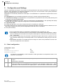
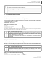
9.1 Basic configuration
[P055] ZONE – Zone
Data type
Adjustment range interfaces
Adjustment range BA
Bit
1, [0]
off, [on]
For reasons of compatibility to PSG-controllers of older generations, the adjustment value is over
interface in reverse logic.
1
off
At control output in accordance with operating mode (control/manual mode) actuating signals are
output.
All alarms are calculated.
[0]
[on]
At control outputs no actuating signals are output.
Only those alarms are calculated which are released in the parameters [P051] ALP1 - Alarm
Calculation 1 with Passive Zones and [P052] ALP2 - Alarm Calculation 2 with Passive Zones.
Rev. 1.00.01
Technical changes reserved
PSG Plastic Service GmbH
Operating instructions ETR132PNIO
[P038] COOL - 3-Point Operation
Data type
Adjustment range interfaces
Adjustment range BA
Bit
0, [1]
off, [on]
0
off
The control algorithm works in two-point operation (heating). The output range of the degree of operation in control and manual mode is 0...100%.
At the heating control output, actuating signals are output at positive setting levels, at the cooling
output no actuating signal is output.
[1]
[on]
The control algorithm works in three-position operation (heating/cooling). The output range of the
degree of operation in control and manual mode is -100...100%.
On the heating control output, actuating signals are output at positive setting levels and, on the
cooling output the actuating signals are output at negative setting levels.
[SP22] CELS – Temperature Unit °C/°F
Data type
Adjustment range interfaces
Adjustment range BA
Char
0, [1]
°F, [°C]
Unit of measurement signal.
The measured value is calculated directly in case of controllers with thermo-element and resistance thermometer
inputs. In case of controllers with standard signal inputs, the calculation is implemented on the basis of the scaling
parameters [P047] RG L - Lower Temperature Value at Standard Signal Inputs and [P048] RG H - Upper Temperature Value with Standard Signal Inputs
[SP38] MAXK – Maximum Number of Channels
Data type
Adjustment range interfaces/ multiplier
Adjustment range BA
Byte
1...[32] / 1
1...[32]
The parameter stipulates the zone number for which the regulation, as well as the alarm handling, is processed,
starting from the first zone. The reduction of the zone number does not have any effect on the cycle duration in
case of recording of the measured values.
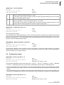
9.2 Configuration inputs
[SP18] SEN1 - Sensor type Zone 1...8
Data type
Adjustment range interfaces/ multiplier
Adjustment range BA
Byte
[0]...255 / 1
[FeL], FeJ, niC, Pt, Str, ni, nSi
The parameter stipulates the type of the sensors ([0 - L (Fe-L)], 1 - J (Fe-J), 2 - K (NiCr), 3 - PT100, 4 - Standard,
5 - NI100, 6 - N (NiCrSi)) which are connected to the measurement inputs of the corresponding zones.
In case of controllers in the implementation TCPt, all eight measurement inputs can be switched over between
thermo-element types (Fe CuNi L, Fe CuNi J, Ni CrNi K, NiCriSi NiSi N) and resistance thermometers (Pt100,
Ni100).
The measurement inputs of controllers in standard signal implementation U and I are not interchangeable. The
sensor type is stipulated with ordering of the device and must be set adjusted according to the implementation.
[SP19] SEN2 - Sensor type Zone 9...16
Data type
Adjustment range interfaces/ multiplier
Adjustment range BA
Byte
[0]...255 / 1
[FeL], FeJ, niC, Pt, Str, ni, nSi
Rev. 1.00.01
Technical changes reserved
35
36
Chapter 9
Configuration and Settings
[SP18] SEN1 - Sensor type Zone 1...8
[SP20] SEN3 - Sensor type Zone 17...24
Data type
Adjustment range interfaces/ multiplier
Adjustment range BA
Byte
[0]...255 / 1
[FeL], FeJ, niC, Pt, Str, ni, nSi
[SP18] SEN1 - Sensor type Zone 1...8
[SP21] SEN4 - Sensor type Zone 25...32
Data type
Adjustment range interfaces/ multiplier
Adjustment range BA
Byte
[0]...255 / 1
[FeL], FeJ, niC, Pt, Str, ni, nSi
[SP18] SEN1 - Sensor type Zone 1...8
[P033] OFFS - Temperature Offset
Data type
Adjustment range interfaces & BA / multiplier
Char
-9.9...[0.0]...9.9 unit of the measured value / 10
The measured value of the measurement input is corrected as follows:
Corrected measured value = measured value + temperature offset
[SP28] OFF1 - Offset Zone 1...8
Data type
Adjustment range interfaces & BA / multiplier
Char
-9.9...[0.0]...9.9 unit of the measured value / 10
For the measurement inputs of the zones 1 to 8 the following applies:
Corrected measured value = measured value + Offset Zone 1...8
[SP29] OFF2 - Offset Zone 9...16
Data type
Adjustment range interfaces & BA / multiplier
Char
-9.9...[0.0]...9.9 unit of the measured value / 10
For the measurement inputs of the zones 9 to 16 the following applies:
Corrected measured value = measured value + Offset Zone 9...16
[SP30] OFF3 - Offset Zone 17...24
Data type
Adjustment range interfaces & BA / multiplier
Char
-9.9...[0.0]...9.9 unit of the measured value / 10
For the measurement inputs of the zones 17 to 24 the following applies:
Corrected measured value = measured value + Offset Zone 17...24
[SP31] OFF4 - Offset Zone 25...32
Data type
Adjustment range interfaces & BA / multiplier
Char
-9.9...[0.0]...9.9 unit of the measured value / 10
For the measurement inputs of the zones 25 to 32 the following applies:
Corrected measured value = measured value + Offset Zone 25...32
Rev. 1.00.01
Technical changes reserved
PSG Plastic Service GmbH
Operating instructions ETR132PNIO
[P047] RG L - Lower Temperature Value at Standard Signal Inputs
Data type
Word
Adjustment range interfaces/ multiplier
-99...[0]...6553.6 unit of the measured value / 10
Adjustment range BA
-99...[0]...999 unit of the measured value / 10
For a measurement input of type standard signal U or I direct on the controller, the parameter stipulates the value
which is displayed in case of a measured value equal to 0/2 VDC and 0/4 mA.
Related with the parameter [P048] RG H - Upper Temperature Value with Standard Signal Inputs a characteristic
curve is defined, with its help the display values e.g for an input of 0...10V are calculated as follows:
Display value = 0.1 x (RG H - RG L) x Measured value + RG L
For measurement recording by CANAIN08/FIN08
at APPL < 128 the actual value is not scaled
at APPL >= 128 the display range of the actual value is defined by RG L and/or RG H
[P036] APPL - Application
Is a thermocouple TC and/or resistance thermometer Pt100 directly connected to the controller, the
parameter is without function.
[P048] RG H - Upper Temperature Value with Standard Signal Inputs
Data type
Word
Adjustment range interfaces/ multiplier
-99...[1000]...6553.6 unit of the measured value / 10
Adjustment range BA
-99...[999] unit of the measured value
For a measurement input of type standard signal U or I direct on the controller, the parameter stipulates the value
which is displayed in case of a measured value equal to 10 VDC and 20 mA.
[P047] RG L - Lower Temperature Value at Standard Signal Inputs
For measurement recording by CANAIN08/FIN08
at APPL < 128 the actual value is not scaled
at APPL >= 128 the display range of the actual value is defined by RG L and/or RG H
[P036] APPL - Application
Is a thermocouple TC and/or resistance thermometer Pt100 directly connected to the controller, the
parameter is without function.
[P057] NoZN - Zone Allocation to Measurement Input on Sensor Interface FIN
Data type
Integer
Adjustment range interfaces & BA / multiplier
[-32]...255 / 1
0
The zone uses the measurement input assigned directly on the controller (Zone X - Measurement Input X)
>0
The zone uses the measurement input on a CANAIN08 or FIN08. Setting value dependent on address of
the CANAIN08/FIN08:
Measurement input = (Address of the CANAIN08/FIN08 x 8) + (Measuring channel
on CANAIN08/FIN08)
Zone 1 employs fifth measuring channel on a CANAIN08/FIN08 with address 2:
Setting adjustment = (2 x 8) + 5 = 21 in case of Zone 1
<0
The zone uses the sensor input of another zone on the controller.
Zone 1 uses measurement input of Zone 10:
Adjustment = -10 in case of Zone 1
Rev. 1.00.01
Technical changes reserved
37
38
Chapter 9
Configuration and Settings
[SP23] INP1 - Function Digital Input 1
Data type
Adjustment range interfaces & BA / multiplier
Byte
[0]...255 / 1
For setting < 100 the parameter is compatible to parameter INPD of controllers sysTemp controllers and is valid for both digital inputs. [SP24] INP2 - Function Digital Input 2 is without function.
In case of setting values greater than 100, the parameter applies only for Digital Input 1. The function is stipulated which the controller implements with activated Digital Input 1.
Digital Input 1
Digital Input 2
Digital Input 1 and 2
0
Regulation on 2. setpoint value
Heating actuator disconnected
Heating actuator disconnected
1
Relative reduction by 2. setpoint
value
Heating actuator disconnected
Heating actuator disconnected
2
Regulation on 2. setpoint value
Regulation on 3. setpoint value
Regulation on 3. setpoint value
3
Relative reduction by 2. setpoint
value
Relative reduction by 3. setpoint
value
Relative reduction by 3. setpoint
value
4
Regulation on 2. setpoint value
Regulation on 3. setpoint value
Regulation on 4. setpoint value
5
Relative reduction by 2. setpoint
value
Relative reduction by 3. setpoint
value
Relative reduction by 4. setpoint
value
6
Regulation on 2. setpoint value
Reset-acknowledge stored alarms Reset-acknowledge stored alarms
7
Relative reduction by 2. setpoint
value
Reset-acknowledge stored alarms Reset-acknowledge stored alarms
8
Regulation on 2. setpoint value
Start program function
Start program function
9
Relative reduction by 2. setpoint
value
Start program function
Start program function
10
Regulation on 2. setpoint value
Regulation on 3. setpoint value
Regulation on 2. setpoint value
11
Relative reduction by 2. setpoint
value
Relative reduction by 3. setpoint
value
Relative reduction by 2. setpoint
value
12
Regulation on 2. setpoint value
(Zones 1-16)
Regulation on 2. setpoint value
(Zones 17-32)
Regulation on 2. setpoint value
(Zones 17-32)
13
Reduction relative by 2. setpoint
value (Zones 1-16)
Reduction relative by 2. setpoint
value (Zone 17-32)
Reduction relative by 2. setpoint
value (Zone 17-32)
14
Regulation on 2. setpoint value
Regulation on 3. setpoint value
Regulation on 3. setpoint value
15
Relative reduction by 2. setpoint
value
Relative reduction by 3. setpoint
value
Start diagnostic function for sensor/heating
16
Relative reduction by 2. setpoint
value
Setpoint value increase relative by Setpoint value increase relative by
3. setpoint value
3. setpoint value
17
Relative reduction by 2. setpoint
value
Setpoint value increase relative by Start diagnostic function for sen3. setpoint value
sor/heating
18
Relative reduction by 2. setpoint
value
Time-controlled setpoint value in- Time-controlled setpoint value increase relative by 3. setpoint val- crease relative by 3. setpoint value
ue
19
Percentage reduction/increase by Percentage reduction/increase by Percentage reduction/increase by
2. setpoint value
3. setpoint value
4. setpoint value
20
Regulation on 2. setpoint value
Disconnected heating actuator,
signal low active
Disconnected heating actuator,
signal low active
21
Relative reduction by 2. setpoint
value
Disconnected heating actuator,
signal low active
Disconnected heating actuator,
signal low active
22
Regulation on 2. setpoint value
Regulation on 3. setpoint value
Passivate all zones
23
Relative reduction by 2. setpoint
value
Relative reduction by 3. setpoint
value
Passivate all zones
Rev. 1.00.01
Technical changes reserved
PSG Plastic Service GmbH
Operating instructions ETR132PNIO
Digital Input 1
Digital Input 2
Digital Input 1 and 2
24
Heating actuator disconnected
(Zones 1-16), signal high active
Heating actuator disconnected
(Zones 17-32), signal high active
Heating actuator disconnected
(Zones 17-32), signal high active
25
Heating actuator disconnected
(Zones 1-16), signal low active
Heating actuator disconnected
(Zones 17-32), signal low active
Heating actuator disconnected
(Zones 17-32), signal low active
26
Regulation on 2. setpoint value
Start program function
Passivate all zones
27
Relative reduction by 2. setpoint
value
Start program function
Passivate all zones
28
Degree of operation boost (degree Activate BA input block
of operation = 100%) for 10 seconds
Activate BA input block
29
Reset-acknowledge stored alarms Activate BA input block
Activate BA input block
30
Regulation on 2. setpoint value
Disconnected heating actuator,
signal low active
Disconnected heating actuator,
signal low active
31
Relative reduction by 2. setpoint
value
Disconnected heating actuator,
signal low active
Disconnected heating actuator,
signal low active
32... n.a.
39
n.a.
n.a.
40
Regulation on 2. setpoint value
Instant group release when 2. set- Instant group release when 2. setpoint value < setpoint value.
point value < setpoint value.
41
Relative reduction by 2. setpoint
value
Instant group release
Instant group release
n.a.
n.a.
42... n.a.
99
100
Regulation on 2. setpoint value
101
Regulation on 3. setpoint value
102
Regulation on 4. setpoint value
103
Relative reduction by 2. setpoint value
104
Relative reduction by 3. setpoint value
105
Relative reduction by 4. setpoint value
106
Setpoint value increase relative by 2. setpoint value
107
Setpoint value increase relative by 3. setpoint value
108
Setpoint value increase relative by 4. setpoint value
109
Percentage reduction/increase by 2. setpoint value
110
Percentage reduction/increase by 3. setpoint value
111
Percentage reduction/increase by 4. setpoint value
112
Absolute reduction to 2. setpoint value, if 2. setpoint value < setpoint value
113
Absolute reduction to 3. setpoint value, if 3. setpoint value < setpoint value
114
Absolute reduction to 4. setpoint value, if 4. setpoint value < setpoint value
115
Disconnected heating actuator, signal active high
116
Disconnected heating actuator, signal low active
117
Heating actuator disconnected (Zones 1-16), signal high active
118
Heating actuator disconnected (Zones 1-16), signal low active
119
Heating actuator disconnected (Zones 17-32), signal high active
120
Heating actuator disconnected (Zones 17-32), signal low active
Rev. 1.00.01
Technical changes reserved
39
40
Chapter 9
Configuration and Settings
121
Passivate all zones
122
Activate BA input block
123
Reset-acknowledge stored alarms
124
Degree of operation boost (degree of operation = 100%) for 10 seconds
125... n.a.
199
200
Start diagnostic function for sensor/heating (pushbutton)
201
Release all groups (group function) (pushbutton)
202
Start program function
203... n.a.
255
[SP24] INP2 - Function Digital Input 2
Data type
Adjustment range interfaces & BA / multiplier
Byte
[0]...255 / 1
In case of setting values of less than [SP23] INP1 - Function Digital Input 1100, INP2 is without
function.
In case of setting values less than 100, no function is implemented.
In case of setting values greater than 100, the parameter applies only for Digital Input 2. The function is stipulated which the controller implements with activated Digital Input 2.
100
Regulation on 2. setpoint value
101
Regulation on 3. setpoint value
102
Regulation on 4. setpoint value
103
Relative reduction by 2. setpoint value
104
Relative reduction by 3. setpoint value
105
Relative reduction by 4. setpoint value
106
Setpoint value increase relative by 2. setpoint value
107
Setpoint value increase relative by 3. setpoint value
108
Setpoint value increase relative by 4. setpoint value
109
Percentage reduction/increase by 2. setpoint value
110
Percentage reduction/increase by 3. setpoint value
111
Percentage reduction/increase by 4. setpoint value
112
Absolute reduction to 2. setpoint value, if 2. setpoint value < setpoint value
113
Absolute reduction to 3. setpoint value, if 3. setpoint value < setpoint value
114
Absolute reduction to 4. setpoint value, if 4. setpoint value < setpoint value
115
Disconnected heating actuator, signal active high
116
Disconnected heating actuator, signal low active
117
Heating actuator disconnected (Zones 1-16), signal high active
118
Heating actuator disconnected (Zones 1-16), signal low active
119
Heating actuator disconnected (Zones 17-32), signal high active
120
Heating actuator disconnected (Zones 17-32), signal low active
121
Passivate all zones
122
Activate BA input block
123
Reset-acknowledge stored alarms
124
Degree of operation boost (degree of operation = 100%) for 10 seconds
Rev. 1.00.01
Technical changes reserved
PSG Plastic Service GmbH
Operating instructions ETR132PNIO
125... n.a.
199
200
Start diagnostic function for sensor/heating (pushbutton)
201
Release all groups (group function) (pushbutton)
202
Start program function
203... n.a.
255
9.3 Configuration/Functions Outputs
[P002] OPWR – Degree of Operation
Data type
Adjustment range interfaces & BA / multiplier
Char
-100...[0]...100% / 1
Actuating variable. Calculated in the standard operation through controllers. In the manual mode, the specification
is implemented manually by the operator.
[P003] MANU – Manual Mode
[P039] RELH – Heating Relay Output
Data type
Adjustment range interfaces
Adjustment range BA
Bit
[0], 1
[off], on
Specifies the manner in which the actuating signal is output at the Heating control output. Through this, an adaptation of the actuating signal to the actuator (SSR, relay) is possible.
0
off
Output of the actuating variable through fast clocked pulse groups (e.g. for the output to solid state
relay). The minimum pulse width is 40 ms.
1
on
Per sampling cycle (corresponds to sampling time) the actuating variable is output in the block (onetime switching on and off of the setting output). The operating time is proportional to the degree of
operation with reference to the sampling time.
In order to take care of the actuator the [P018] CT-H - Heating Sampling Time is set to a minimum
of 10 seconds.
[P040] RELC – Cooling Relay Output
Data type
Adjustment range interfaces
Adjustment range BA
Bit
0, [1]
off, [on]
Stipulates the type of the output of the actuating signal at the cooling control output. Used for the adaptation of the
actuating signal to the actuator (SSR, relay).
0
off
Output of the actuating variable through fast clocked pulse groups (e.g. for the output to solid state
relay). The minimum pulse width is 40 ms.
1
on
Per sampling cycle (corresponds to sampling time) the actuating variable is output in the block (onetime switching on and off of the setting output). The operating time is proportional to the degree of
operation with reference to the sampling time.
The [P022] CT-C - Cooling Sampling Time is limited to a minimum of 10 seconds.
[P023] OUTH – Heating Degree of Operation Damping
Data type
Char
Adjustment range interfaces & BA / multiplier
0...[100]% / 1
Rev. 1.00.01
Technical changes reserved
41
42
Chapter 9
Configuration and Settings
Correction of the heating degree of operation:
Corrected degree of operation = degree of operation x 0.01 x setting value
Setting value OUTH = 75
Uncorrected degree of operation = 85%
Corrected degree of operation = 85% x 0.01 x 75 = 63% (rounded)
[P024] OUTC – Cooling Degree of Operation Damping
Data type
Char
Adjustment range interfaces & BA / multiplier
0...[100]% / 1
Correction of the degree of operation cooling:
Corrected degree of operation = degree of operation x 0.01 x setting value
Setting value OUTC = 75
Uncorrected degree of operation = -40%
Corrected degree of operation = -40% x 0.01 x 75 = -30%
[P025] OUT% – Maximum Degree of Operation in Manual Mode
Data type
Char
Adjustment range interfaces & BA / multiplier
0...[100]% / 1
Limitation of the maximum heating degree of operation in manual mode. Can be set e.g. as a safety function for
the function [P037] TC-A – Manual Mode after Sensor Break.
9.4 Basic Functions
[P003] MANU – Manual Mode
Data type
Adjustment range interfaces
Adjustment range BA
Bit
[0], 1
[off], on
[0]
[off]
Regulation active. Degree of operation is calculated from the control algorithm.
1
on
Regulation deactivated. Manual specification of the [P002] OPWR – Degree of Operation.
In manual mode, a zone, e.g. in case of a defect of the measuring means (e.g. sensor break with
thermocouple) can be further operated in emergency operation.
In manual mode the alarms are further monitored and the heating current monitoring also continues
to function.
[P037] TC-A – Manual Mode after Sensor Break
[P028] STMO - Startup Operation
Data type
Adjustment range interfaces
Adjustment range BA
Bit
[0], 1
[off], on
Function for temperature control field of application of hot conduit systems for the dehydrating of heating elements
after start of temperature control.
If, after a reset of the controller
in case of an active zone
whose setpoint value is greater than 100°C
a temperature actual value is identified less than 90°C, the time set adjusted under [P029] STT - Startup Operation Initiation Time is controlled to 100°C. The time starts when the actual values of all zones of the controller,
Rev. 1.00.01
Technical changes reserved
PSG Plastic Service GmbH
Operating instructions ETR132PNIO
with which the startup operation is activated, have been one-time in the tolerance band of the startup setpoint value of 100°C.
In case of networking of several controllers over CAN, the function works with controller-overall effect.
[P029] STT - Startup Operation Initiation Time
Data type
Adjustment range interfaces/ multiplier
Adjustment range BA
Byte
[0]...255 minutes / 1
[0]...99 minutes
[P028] STMO - Startup Operation
[P054] NoCO - Leading Zone
Data type
Adjustment range interfaces & BA / multiplier
Byte
[0]...255 / 1
Function used to control the zone with the output value of another zone. It is used e.g. in case of defect of the error
sensing device corresponding to the zone (e.g. sensor break). In order to maintain the operation of the control
zone in spite of that, the zone in the leading zone operation is operated with the degree of operation of a similar
zone.
[0]
Leading zone operation deactivated. Zone employs its own degree of operation calculated through the regulation or specified manually.
>0
The zone employs the degree of operation of the zone specified in the setting value.
Since the function works with controller-overall effect (Prerequisite: Controller connected over CAN) the
controller address is a component part of the setting value:
Leading zone NoCO = (DIP switch setting x 32) + zone number
In the case of a zone with defective sensor, the degree of operation of the fifth zone of the controller
should be employed as leading zone, with which the addressing DIP Switches 1 and 2 are set to on
(corresponds to Address 3): NoCO = (3 x 32) + 5 = 101
The output value output is completely synchronous, if
the zone is located on the same controller
the [P053] K-CO – Amplification Factor for Zone in Leading Mode is set equal to 0
If both conditions are not fulfilled, an asynchronous output value signal is then implemented.
A cascading of the leading zone is not permissible. In case of invalid inputs (when e.g. a zone is
entered as a leading zone which itself has a reference to a leading zone), the setting value is set
automatically to 0.
[P053] K-CO – Amplification Factor for Zone in Leading Mode
Data type
Char
Adjustment range interfaces/ multiplier
-128...[0]...128 / 1
Adjustment range BA
-99...[0]...100
Enables the adaptation of the output value of the leading zone for the zone led.
Adapted degree of operation = Degree of operation * (1 + (0.01 x K-CO))
The degree of operation of the leading zone should basically be increased by 10%: K-CO = 10
In the case of an output value of the leading zone of 50%, the following corrected output value is calculated:
Adapted output value = 50% * (1 + (00.1 x 10)) = 55%
[P054] NoCO - Leading Zone
Rev. 1.00.01
Technical changes reserved
43
44
Chapter 9
Configuration and Settings
[P049] TRMP – Temperature Ramp
Data type
Adjustment range interfaces/ multiplier
Adjustment range BA
Word
[0]...6553.5 / 10
-99.9...[0]...99.9 Unit of the measurement input / minute
Characteristic behavior of the setpoint value at setpoint value changes.
[0.0]
In case of setpoint value jump with setpoint value increases and setpoint value decreases.
>0.0
In case of setpoint value increases, the setpoint value is ramped with the setting value to the final setpoint
value, starting from the current actual value. Setpoint value jump with setpoint value decreases.
<0.0
In case of setpoint value increases and setpoint value decreases, the setpoint value is ramped with the
setting value to the final setpoint value starting from the current actual value.
[P050] ARMP – Automatic Ramp
Data type
Adjustment range interfaces/ multiplier
Adjustment range BA
Bit
[0], 1
[off], on
[0]
[off]
In the case of the zone, the automatic ramp operation is deactivated.
1
on
In the case of the zone, the automatic ramp operation is activated.
All active zones assigned to a group ([P058] GPNo - Group Number) with a setpoint value greater than 0°C/32°F,
with which the automatic ramping function is activated, are heated up at a setpoint value change > 30 °C automatically with respect to the actual value of the zone with the least rate of rise. The zone with the least rate of rise is
called the reference zone.
With the aid of the function, mechanical stresses through large temperature gradient between zones of different
rate of rise can be avoided.
In case of networking of several controllers over CAN, the function works with controller-overall effect.
The automatic ramping function can also be employed in combination with the [P035] IDEN - Heating Identification. With that, the uniform warming is implemented also in the case where the controller does not yet have
any knowledge about the control zone and where this will be first calculated on the basis of the identification
which progresses parallel to the automatic ramp.
If the temperature difference of a zone to the reference zone is at least 30 Kelvin, or if no heating current is measured by a zone any longer, the zone is taken from the link of the automatic ramp after a time of 20 seconds.
The automatic ramp requires one (at least once) executed identification Heating.
[SP26] GAP – Tolerance Band for Automatic Ramp
Data type
Byte
Adjustment range interfaces/ multiplier
0...[5]...25.5 Unit of measurement input / 10
Adjustment range BA
0...[5]...20
Unit of the measurement input
Stipulation of the tolerance band indicating how much the measured values of the zones may differ in automatic
ramp operation. Zones which exceed the tolerance range are trimmed in the degree of operation.
[P037] TC-A – Manual Mode after Sensor Break
Data type
Adjustment range interfaces
Adjustment range BA
Bit
[0], 1
[off], on
Stipulates the characteristic behavior of the zone in the case of a sensor break.
[0]
[off]
Function is deactivated.
1
on
At sensor break it is automatically switch to manual mode. The output value is calculated dependent
on the mean output value from the last cycles before sensor break.
Rev. 1.00.01
Technical changes reserved
PSG Plastic Service GmbH
Operating instructions ETR132PNIO
Sensor break during heating-up can lead to overheating when automatic transfer of degree of operation, because in this phase the maximal degree of operation is output. A limitation for the degree of
operation in manual mode can be set by parameter [P025] OUT% – Maximum Degree of Operation
in Manual Mode.
[P041] TCAL – Monitoring of Sensor SAL
Data type
Adjustment range interfaces
Adjustment range interfaces & BA
Bit
[0], 1
[off], on
Complex, dynamic monitoring function of the measuring element (sensor) per zone. The function helps to identify
(as well as the static monitoring on sensor break and sensor incorrect polarity) to avoid additional error states in
the area of the sensor and damage to the control zone e.g. through overheating.
An FAL alarm is output, when
no identification is running
at active heating current monitoring (AMPD <> 0, AMPN > 0, AMPT > 0)
no current alarm is pending
Two causes can result in a SAL alarm:
If the difference between current actual value and the last sampled actual value is
[P018] CT-H - Heating Sampling Time < 4 sec => 30K in 0.5 sec
[P018] CT-H - Heating Sampling Time >= 4 sec => 20K in 0.5 sec
then a FAL alarm is immediately triggered after a pre-determined number of control cycles, since, with this actual
value characteristic, it must involve a defect on the sensor line or on the sensor.
If the temperature actual value does not increase by 4 K in standard operation in case of maximum degree of
operation ([P023] OUTH – Heating Degree of Operation Damping) within a pre-determined time, then a FAL
alarm is triggered.
The response time of the sensor short-circuit monitoring
can be stipulated either manually ([P042] FALT - Sensor Short-Circuit Monitoring Time <> 0) or
or
is derived automatically from the sampling time of the zone ([P042] FALT - Sensor Short-Circuit Monitoring
Time = 0).
Due to the response time, mistakenly triggered FAL alarms are reduced. The response time is started at the time
when all prerequisites for a FAL alarm are satisfied. The response time is reset when one of the prerequisites
for a FAL is not satisfied during the response time.
According to the operating point, different FAL response times are worked with:
in the setpoint value band: FAL response time = 30 x heating sampling time
outside of the setpoint value band: FAL response time = 20 x heating sampling time
minimal response time (for CT-H < 15 seconds): FAL response time = 20 x 15 seconds
The setpoint value band is derived directly from the [P015] XP-H - Heating Proportional Band:
SWB = XPH x 4
[P042] FALT - Sensor Short-Circuit Monitoring Time
[P042] FALT - Sensor Short-Circuit Monitoring Time
Data type
Word
Adjustment range interfaces/ multiplier
[0]...6553.6 seconds / 10
Adjustment range BA
[0]...999 seconds
[0]
Not active.
Rev. 1.00.01
Technical changes reserved
45
46
Chapter 9
Configuration and Settings
>0
Period after which a FAL alarm is output when the temperature actual value in standard operation at maximum degree of operation ([P023] OUTH – Heating Degree of Operation Damping) has not increased by
4 K.
([P041] TCAL – Monitoring of Sensor SAL and the stipulated FAL response times are without function)
9.5 Setpoint Value Functions
[P001] SP - Set Point
Data type
Adjustment range interfaces/ multiplier
Adjustment range BA
Integer
[0.0]...6553.6 Unit of the measurement input / 10
0...999
Unit of the measurement input
Main setpoint value on which control is implemented when 2., 3. or 4. setpoint value not active.
With setpoint value 0°C/32°F, the zone is passivated. Only the current alarm at "switched off heating" continues
to be monitored.
With setpoint value 0°C/32°F, the control algorithm is reinitialized
With active manual mode, the setpoint value is without function.
[P012] SP2 – 2. Setpoint / 2. Lowering/Reduction Value
Data type
Integer
Adjustment range interfaces/ multiplier
[0.0]...1999.9 Unit of the measurement input / 10
Adjustment range BA
[0]...999 Unit of the measurement input
The second setpoint value is employed either (a) directly as a setpoint value or (b) as a setpoint value in the program function.
(a) Directly as a setpoint value
The second setpoint value is activated
over a digital input for all zones simultaneously
over the data interfaces for every zone separately.
Over the parameters [SP23] INP1 - Function Digital Input 1 and [SP24] INP2 - Function Digital Input 2, it is
stipulated, whether
control is implemented on a second setpoint value or whether
control is implemented on the [P001] SP - Set Point reduced by the lowering value.
The reduction over digital input has a higher priority than the zone-specific software reduction.
b) As a setpoint value in the program function
The controller has a program function. With this, an arbitrary setpoint value profile can be realized with the four
setpoint values.
If the program function should be used, then
the [P028] STMO - Startup Operation must be deactivated.
the system parameter [SP23] INP1 - Function Digital Input 1 is set adjusted to 8 or 9.
The program function is started by the negative signal edge at the digital input 2.
The following setpoint value profile will run:
[P012] SP2 – 2. Setpoint / 2. Lowering/Reduction Value with[P030] STT2 - Start-up Time of 2. Set Point/2.
Lowering Value
[P013] SP3 – 3. Setpoint / 3. Lowering/Reduction Value with[P031] STT3 - Start-up Time of 3. Set Point/3.
Lowering Value
[P014] SP4 – 4. Setpoint / 4. Lowering/Reduction Value with[P032] STT4 - Start-up Time of 4. Set Point/4.
Lowering Value
Rev. 1.00.01
Technical changes reserved
PSG Plastic Service GmbH
Operating instructions ETR132PNIO
The start-up time for the 2. setpoint value is not started until the actual values
of all active zones
whose setpoint value is not equal to 0°C
have reached the tolerance band around the second setpoint value. That is, the start-up time for the second setpoint value is not started until the "slowest" zone reaches the tolerance band around the second setpoint value.
It is to be ensured that the actual value can reach the tolerance band, because otherwise the program function will never be started.
[P013] SP3 – 3. Setpoint / 3. Lowering/Reduction Value
Data type
Integer
Adjustment range interfaces/ multiplier
[0.0]...1999.9 Unit of the measurement input / 10
Adjustment range BA
[0]...999 Unit of the measurement input
[P012] SP2 – 2. Setpoint / 2. Lowering/Reduction Value
[P014] SP4 – 4. Setpoint / 4. Lowering/Reduction Value
Data type
Integer
Adjustment range interfaces/ multiplier
[0.0]...1999.9 Unit of the measurement input / 10
Adjustment range BA
[0]...999 Unit of the measurement input
[P012] SP2 – 2. Setpoint / 2. Lowering/Reduction Value
[P026] SPLO – Lower Setpoint Value Limit
Data type
Adjustment range interfaces/ multiplier
Adjustment range BA
Integer
[0.0]...1999.9 Unit of the measurement input / 10
[0]...999 Unit of the measurement input
Lower input limitation for all temperature setpoints.
[P027] SPHI – Upper Setpoint Value Limit
Data type
Adjustment range interfaces/ multiplier
Adjustment range BA
Integer
0.0...[500.0]...1999.9 Unit of measurement input / 10
0...[500]...999 Unit of the measurement input
Upper input limitation for all temperature setpoints.
Exceeding the upper setpoint value limit an alarm is activated, when more than 5 seconds
(Temperature actual value > SPHI + 5K)
Output in manual mode: degree of operation -100%
Output in control mode: degree of operation -100%... 0%, depending on control status
The alarm resets, as long as not otherwise configured, when the actual temperature value falls below the limit value.
An alarm is suppressed, when
SPHI < 150°C
[P030] STT2 - Start-up Time of 2. Set Point/2. Lowering Value
Data type
Byte
Adjustment range interfaces/ multiplier
[0]...255 minutes / 10
Adjustment range BA
[0]...99 minutes
The setting value 0 deactivates the start-up time of the second setpoint value and/or the second lowering value.
Rev. 1.00.01
Technical changes reserved
47
48
Chapter 9
Configuration and Settings
[P012] SP2 – 2. Setpoint / 2. Lowering/Reduction Value
[P031] STT3 - Start-up Time of 3. Set Point/3. Lowering Value
Data type
Byte
Adjustment range interfaces/ multiplier
[0]...255 minutes / 1
Adjustment range BA
[0]...99 minutes
The setting value 0 deactivates the start-up time of the third setpoint value and/or the third lowering value.
[P030] STT2 - Start-up Time of 2. Set Point/2. Lowering Value
[P012] SP2 – 2. Setpoint / 2. Lowering/Reduction Value
[P032] STT4 - Start-up Time of 4. Set Point/4. Lowering Value
Data type
Byte
Adjustment range interfaces/ multiplier
[0]...255 minutes / 1
Adjustment range BA
[0]...99 minutes
The setting value 0 deactivates the start-up time of the fourth setpoint value and/or the fourth lowering value.
[P030] STT2 - Start-up Time of 2. Set Point/2. Lowering Value
[P012] SP2 – 2. Setpoint / 2. Lowering/Reduction Value
Rev. 1.00.01
Technical changes reserved
PSG Plastic Service GmbH
Operating instructions ETR132PNIO
9.6 Control characteristic
The controller has two control parameter sets for heating and cooling. The second control parameter set is without function.
The automatic calculation of the control parameters comes about through the so-called identification in case of
setpoint value changes, above a pre-determined height. The calculation of the control parameters cooling is coupled with the calculation of the heating control parameters.
[P015] XP-H - Heating Proportional Band
Data type
Adjustment range interfaces/ multiplier
Adjustment range BA
Byte
0.0...[9.9]...25.5% / 10
0.0...[9.9]...25.5%
The P content changes the output of the PID controller proportional to the deviation between setpoint and actual
value.
The proportional band is the range of the process variable, in which this linear reinforcement occurs before the
output achieves its maximum or minimum. This range is indicated in percent of the measuring range. In order that
the adjusted proportional band is independent of the sensor type and/or measuring range, the controller measuring range in case of PSG-controllers is assumed at 500°C (1% corresponds to 5 K).
The amplification of the controller decreases with increasing proportional band, and increases with decreasing
proportional band. In case of a proportional band selected too small, the controller reacts to small deviations so
severely that the control system oscillates. On the other hand, a proportional band which is selected too large
makes the regulation very slow. The controller no longer reacts adequately to faults. In case of utilization of pure
proportional band controllers in the control system, the deviation cannot be eliminated fully. There results the socalled permanent deviation.
[P016] TD-H - Heating Derivative Time
Data type
Adjustment range interfaces & BA / multiplier
Byte
0...[2]...255 seconds / 1
The differential content (D content) of the PID controller reacts in a leading way to the rate of change of the deviation or the actual value.
The differential content then supplies only a actuating variable, if the deviation or the actual value is changed.
Therefore it cannot be used in order to stabilize a constant control deviation. That also explains the utilization of
the D regulator only in association with P or PI characteristic.
The importance of the differential content in practice lies in the fact that the controller supplies actuating variables
when the deviation first arises. The D characteristic makes the controller more rapid than a pure P or PI controller.
However, the D characteristic cannot distinguish between real deviations and so-called hum disturbances, i.e.
higher frequency superpositions on the measurement variable. A differential content which is set adjusted too
large reacts to the disturbances with fast changes of the actuating variable, through which the control system becomes very unsteady.
[P017] TI-H - Heating Integral Time
Data type
Adjustment range interfaces/ multiplier
Adjustment range BA
Word
0...[9]...65536 seconds / 1
0...[9]...999 seconds
With the integral content (I content) of the controller, a continuous change of the controller output value is achieved
until the permanent deviation is stabilized to zero. With this, a permanent deviation is prevented.
The speed with which the stabilizing of the deviation happens and/or the influence of the I content on the actuating
signal, is a function of the integral time (also: Integral time). A short integral time means a great influence of the I
content on the setting value, i.e. it is integrated fast. A large integral time performs in reverse.
If the proportional band is changed, this also means a changed time-related characteristic with unchanged integral
time.
The maximum of the [P035] IDEN - Heating Identificationcalculated parameter value is 1275
Rev. 1.00.01
Technical changes reserved
49
50
Chapter 9
Configuration and Settings
[P018] CT-H - Heating Sampling Time
Data type
Adjustment range interfaces/ multiplier
Adjustment range BA
Byte
[0]...255 seconds / 1
[0]...60 seconds
The sampling time defines a time period after which a [P002] OPWR – Degree of Operation, which is recalculated from the control algorithm is output at the control output.
The sampling time is directly dependent on the dynamics of the controlled system and it is directly stipulated at
the beginning of the [P035] IDEN - Heating Identification
[P019] XP-C - Cooling Proportional Band
Data type
Adjustment range interfaces/ multiplier
Adjustment range BA
Byte
0.0...[9.9]...25.5% / 10
0.0...[9.9]...25.5%
[P015] XP-H - Heating Proportional Band
[P020] TD-C - Cooling Derivative Time
Data type
Adjustment range interfaces & BA / multiplier
Byte
0...[2]...255 seconds / 1
[P016] TD-H - Heating Derivative Time
[P021] TI-C - Cooling Integral Time
Data type
Adjustment range interfaces/ multiplier
Adjustment range BA
Word
0...[9]...65535 seconds / 1
0...[9]...999 seconds
[P017] TI-H - Heating Integral Time
[P022] CT-C - Cooling Sampling Time
Data type
Adjustment range interfaces/ multiplier
Adjustment range BA
[P018] CT-H - Heating Sampling Time
Rev. 1.00.01
Technical changes reserved
Byte
[0]...255 seconds / 1
[0]...60 seconds
PSG Plastic Service GmbH
Operating instructions ETR132PNIO
[P034] ONLC - Online Control
Data type
Adjustment range interfaces/ multiplier
Adjustment range BA
Bit
0, [1]
off, [on]
0
off
Without function.
[1]
[on]
After the calculation of the control parameters through the [P035] IDEN - Heating Identification the
characteristic behavior of the control zone is compared with the characteristic behavior of one controller-internal-filed model of the controlled system.
In case of deviations of the characteristic behavior from real controlled system and the section model, the control parameters are corrected appropriately.
The control parameters heating are not modifiable. They are overwritten immediately again
through the control parameters calculated from the section model.
See Table Overview Adaptation Methods of Control Parameters
[P035] IDEN - Heating Identification
Data type
Adjustment range interfaces/ multiplier
Adjustment range BA
Bit 1
0, [1]
off, [on]
In the identification phase the controller determines the mathematic model of a controlled system, which is saved
in the controller. The control parameters are calculated. Settings of parameter see Table Overview Adaptation
Methods of Control Parameters
[P045] CFIX – Cooling Parameter fixed (Heating Identification)
Data type
Bit
Adjustment range interfaces/ multiplier
[0], 1
Adjustment range BA
[off], on
Specifies whether the Cooling control parameters are derived from the Heating control parameters after identification (only for 3-point zones).
Settings of parameter see Table Overview Adaptation Methods of Control Parameters
Rev. 1.00.01
Technical changes reserved
51
Chapter 9
Configuration and Settings
[P061]
ALGO
Calculation of control parameter set
Heating
[P035] IDEN - Heating Identification
Calculation of control parameter set
Cooling on identification Heating
[P045] CFIX – Cooling Parameter fixed
(Heating Identification)
[P045] CFIX = on
Control parameter set cooling are not modified by identification heating.
Controller is switched on
Status change of zone passive to zone active
Setpoint value <= 0°C / 0°F
[P045] CFIX = off
Calculation of control parameter set cooling
based on control parameters heating after end
of identification phase heating.
after first setpoint value increase with control deviation > 50K.
Start of identification phase, in case of rise of actual value within 10 seconds < 0,4K (drift control). See *)
0 / 3 / 4 MAControl **)
[P035] IDEN = on
Calculation of control parameters heating after a
zone reset. i.e.
[P035] IDEN = off
No calculation of control parameters heating in
case of heating up. See *)
-
[P035] IDEN = on
Calculation of control parameters heating after a
zone reset. i.e.
[P045] CFIX = on
Control parameter set cooling are not modified by identification heating.
Controller is switched on
Status change of zone passive to zone active
Setpoint value <= 0°C / 0°F
[P045] CFIX = off
Calculation of control parameter set cooling
based on control parameters heating after end
of identification phase heating.
after first setpoint value increase with control deviation > 50K.
Start of identification phase, in case of rise of actual value within 10 seconds < 0.4K (drift control). See *)
[P035] IDEN = off
No calculation of control parameters heating in
case of heating up. See *)
1 / 2 DYNControl**)
0 / 3 / 4 / 5 MAControl **)
[P061]
ALGO
Table Overview Adaptation Methods of Control Parameters
1 / 2 / 6 DYNControl**)
52
-
*) Online control [P034] ONLC - Online Control monitors on base of the control parameter set heating
essential changes on the structure of the control system and corrects if necessary the control parameter set heating.
**) Special see [P061] ALGO – Algorithm
Rev. 1.00.01
Technical changes reserved
[P061]
ALGO
PSG Plastic Service GmbH
Operating instructions ETR132PNIO
Calculation of control parameter set
Cooling after setpoint value change of -30K
(independent of parameters)
Calculation of control parameter set
Cooling after code number input
0 / 3 / 4 MAControl **)
On setpoint value change > -30K a cooling adap- Independent of setting of CFIX the code numbers
tation is started.
111 and 112 control the cooling adaptation.
On setpoint value change > -30K a cooling adap- Code number 111: Calculation of control parametation is started and the control parameter set cool- ter sets of all 3-point operation zones (COOL = on),
with setpoint value > 0°C / 0°F.
ing is calculated.
Code number 112: Calculation of control parameters of selected zones. Zone selection by setting of
Start of cooling adaptation, in case of rise of actual
bit 0x80 in control byte of zones. Bit 0x08 in control
value within 10 seconds <= +/- 3,5K (drift control).
byte is reset automatically.
-
-
Start of cooling adaptation, in case of rise of actual
value within 10 seconds <= +/-2K (drift control) and
all actual values within tolerance band of 2K
around setpoint value.
Independent of setting of CFIX the code numbers
111 and 112 control the cooling adaptation.
1 / 2 DYNControl **)
Code number 111: Calculation of control parameter sets of all 3-point operation zones (COOL = on),
with setpoint value > 0°C / 0°F.
Code number 112: Calculation of control parameters of selected zones. Zone selection by setting of
bit 0x80 in control byte of zones. Bit 0x08 in control
byte is reset automatically initiated by code number
112.
-
Start of cooling adaptation, in case of rise of actual
value within 10 seconds <= +/-2K (drift control) and
all actual values within tolerance band of 2K
around setpoint value.
**) Special see [P061] ALGO – Algorithm
Rev. 1.00.01
Technical changes reserved
53
54
Chapter 9
Configuration and Settings
[P061] ALGO – Algorithm
Data type
Adjustment range interfaces/ multiplier
Adjustment range BA
Byte
[0]...255 /1
[0]...6
Stipulates which algorithm is employed for the regulation of the zone.
Settings of parameter see Table Overview Adaptation Methods of Control Parameters
ALGO = [0]
MAControl
Suitable for all modes of actuating signal output (PWM/pulse cooling)
ALGO = 1
DYNControl. Control characteristic more dynamic than that of the MAControl.
The calculation of the control parameters is implemented during the identification phase, up
to reaching the setpoint value.
ALGO = 2
DYNControl.
The calculation of the control parameters is implemented during the identification phase to
10 K prior to reaching the adjusted setpoint value.
ALGO = 3
MAControl for evaporate cooling with intelligent disturbance control ISK (see [P070] PGH
- Pulse Cooling)
ISK includes:
Special degree of operation characteristics for static operation in the range of 0% around
degree of operation
Algorithm for watching of operating point
„Stricter" control characteristics in tolerance band around setpoint value
ALGO = 4
MAControl for evaporate cooling with intelligent disturbance control ISK in alleviated form
(see [P070] PGH - Pulse Cooling)
ISK includes:
Special degree of operation characteristics for static operation in the range of 0% around
degree of operation
Algorithm for watching of operating point
ALGO = 5
MAControl for die bolts
No mixed operation possible between die bolts - and standard control algorithm on one
controller. In case of selection of die bolt control algorithm for at least one zone, then the
die bolt control algorithm is employed with all the other zones.
Heating current monitoring not possible.
Degree of operation resolution 1%
ALGO = 6
DYNControl for die bolts
Remaining operations as under adjustment for ALGO = 5.
Rev. 1.00.01
Technical changes reserved
PSG Plastic Service GmbH
Operating instructions ETR132PNIO
[P062] XPH2 - Heating Proportional Band 2
Data type
Adjustment range interfaces/ multiplier
Adjustment range BA
Byte
0.0...[9.9]...25.5% / 10
0.0...[9.9]...25.5%
Without function
[P063] TDH2 – Heating Derivative Time 2
Data type
Adjustment range interfaces & BA / multiplier
Byte
0...[2]...255 seconds / 1
Without function
[P064] TIH2 – Heating Integral Time 2
Data type
Adjustment range interfaces/ multiplier
Adjustment range BA
Word
0...[9]...65535 seconds / 1
0...[9]...1275 seconds
Without function
[P065] CTH2 - Heating Sampling Time 2
Data type
Adjustment range interfaces/ multiplier
Adjustment range BA
Byte
[0]...255 seconds / 1
[0]...60 seconds
Without function
[P066] XPC2 – Cooling Proportional Band 2
Data type
Adjustment range interfaces/ multiplier
Adjustment range BA
Byte
0.0...[9.9]...25.5% / 10
0.0...[9.9]...25.5%
Without function
[P067] TDC2 – Cooling Derivative Time 2
Data type
Adjustment range interfaces & BA / multiplier
Byte
0...[2]...255 seconds / 1
Without function
[P068] TIC2 – Cooling Integral Time 2
Data type
Adjustment range interfaces/ multiplier
Adjustment range BA
Word
0...[9]...65535 seconds / 1
0...[9]...1275 seconds
Without function
[P069] CTC2 – Cooling Sampling Time 2
Data type
Adjustment range interfaces/ multiplier
Adjustment range BA
Byte
[0]...255 seconds / 1
[0]...60 seconds
Without function
Rev. 1.00.01
Technical changes reserved
55
56
Chapter 9
Configuration and Settings
[P070] PGH - Pulse Cooling
Data type
Adjustment range interfaces
Adjustment range BA
Bit
[0], 1
[off], on
Output method of the actuating signal at the cooling control output.
Prerequisite for the pulse cooling is that [P038] COOL - 3-Point Operation is activated.
[0]
[off]
A PWM signal, proportional to the degree of operation, is output at the Cooling control output.
1
on
In case of the pulse cooling (also: impulse cooling), the pulse duration is constant at the Cooling control output and the pause duration (between 2 impulses) is variable. A pause of variable length follows on a constant pulse.
The pause length is limited by the parameter [P072] PMIN – Minimum Pause Duration and [P073]
PMAX – Maximum Pause Duration. The mandatory pause adjustable through the parameter
[P072] PMIN – Minimum Pause Duration and should prevent the transition from evaporating to
continuous water flow. PMIN should correspond to a cooling pulse in about the reaction time of the
route sections.
Changes of the degree of operation are incorporated only on completion of the current pulse separation.
The relationship between pulse width and maximum pause duration determines the real degree of
operation resolution. For a one-percent degree of operation resolution [P073] PMAX – Maximum
Pause Duration at least the hundred-fold time value of [P071] PULS – Pulse Duration is to be to
set adjusted (please be sure to consider the different units of the parameters).
In case of activated pulse cooling the suitable control algorithm has to be stipulated for each zone (see [P061]
ALGO – Algorithm).
[P071] PULS – Pulse Duration
Data type
Adjustment range interfaces & BA
Word
4...[10]...500 (x10) ms
Defines the duration of an impulse at the control output Cooling in case of active [P070] PGH - Pulse Cooling.
Be sure to consider that the pulse duration is 10x the setting value.
The setting value should
be long enough so that the actuator (e.g. solenoid valve) can act properly
be large enough to determine a change of the actual value
However, the setting value should be selected so that the actual value changes with an individual pulse only insignificantly.
In case of changes of the parameters of the pulse cooling, it is absolutely necessary that the control
parameters be adapted to cooling.
[P070] PGH - Pulse Cooling
[P072] PMIN – Minimum Pause Duration
Data type
Adjustment range interfaces/ multiplier
Adjustment range BA
Word
0.0...[5.0]...6553.5 seconds / 10
0.0...[5.0]...99.9 seconds
Minimum duration between two pulses in case of active [P070] PGH - Pulse Cooling
Rev. 1.00.01
Technical changes reserved
PSG Plastic Service GmbH
Operating instructions ETR132PNIO
[P073] PMAX – Maximum Pause Duration
Data type
Adjustment range interfaces/ multiplier
Adjustment range BA
Word
0.0...[20.0]...6553.5 / 10
0.0...[20.0]...99.9 seconds
Maximum duration between two pulses in case of active [P070] PGH - Pulse Cooling.
9.7 Alarm management
Every zone of the controller is monitored on the following alarm values:
4 Temperature limit value alarms
Current alarm in case of "Heating On", i.e. monitoring of the measured current within a [P010] AMPT - Current
Tolerance by the [P011] AMPN - Current Setpoint Value.
Current alarm in case of "Heating Off", i.e. control as to whether a heating current is measured in the switched
off status of the heating control output.
Sensor break
Sensor incorrect polarity
Sensor short-circuit
The status of the zones can be output as collective alarm on the collective alarm outputs AL1, AL2 and AL3 or,
in case of two-point zones, as zone-specific alarm on the cooling output .
[P004] AL 1 - Limit Value 1
Data type
Adjustment range interfaces & BA / multiplier
Integer
[0]...255 / 1
Stipulation of the first temperature limit value.
Functioning method is stipulated in [P008] ALD1 - Limit Value Definition 1.
[P005] AL 2 - Limit Value 2
Data type
Adjustment range interfaces & BA / multiplier
Integer
[0]...255 / 1
Stipulation of the second temperature limit value.
Functioning method is stipulated in [P008] ALD1 - Limit Value Definition 1.
[P006] AL 3 - Limit Value 3
Data type
Adjustment range interfaces & BA / multiplier
Integer
[0]...255 / 1
Stipulation of the third temperature limit value.
Functioning method is stipulated in [P009] ALD2 - Limit Value Definition 2.
[P007] AL 4 - Limit Value 4
Data type
Adjustment range interfaces & BA / multiplier
Integer
[0]...255 / 1
Stipulation of the fourth temperature limit value.
Functioning method is stipulated in [P009] ALD2 - Limit Value Definition 2.
[P008] ALD1 - Limit Value Definition 1
Data type
Adjustment range interfaces & BA / multiplier
Byte
[0]...255 / 1
Rev. 1.00.01
Technical changes reserved
57
58
Chapter 9
Configuration and Settings
Stipulates the functioning method of the temperature limit values [P004] AL 1 - Limit Value 1 and [P005] AL 2
- Limit Value 2.
Combinations are possible as a setting value. The setting value results from the sum of the identifications.
With a setting value 7 (corresponds to the sum of the identifications 1, 2 and 4) the zone is checked
for absolute [P004] AL 1 - Limit Value 1. An alarm is output only in the case where the actual value
has exceeded the temperature limit value once.
The setting value 0 defines the limit values 1 and 2 as relative limit value alarms.
Identifier
Limit value
Functioning method
1
Limit Value 1 Absolute temperature limit value (Otherwise: Relative temperature limit value).
2
Limit Value 1 Calculation only if limit value is reached.
4
Limit Value 1 Alarm when actual value > limit value (Otherwise: Alarm with actual value < limit value). Applies only for an absolute temperature limit value.
8
Limit Value 1 Without function.
16
Limit Value 2 Absolute temperature limit value (Otherwise: Relative temperature limit value).
32
Limit Value 2 Calculation only if limit value is reached.
64
Limit Value 2 Alarm when actual value > limit value (Otherwise: Alarm with actual value < limit value). Applies only for an absolute temperature limit value.
128
Limit Value 2 Without function.
[P009] ALD2 - Limit Value Definition 2
Data type
Adjustment range interfaces & BA / multiplier
Byte
[0]...255 / 1
Functioning method of the temperature limit values [P006] AL 3 - Limit Value 3 and [P007] AL 4 - Limit Value 4
Combinations are possible as a setting value. The setting value results from the sum of the identifications.
With a setting value 112 (corresponds to the sum of the identifications 16, 32 and 64) the zone is
checked for absolute [P007] AL 4 - Limit Value 4. An alarm is output only in the case where the actual
value has exceeded the temperature limit value once.
The setting value 0 defines the limit values 3 and 4 as relative limit value alarms.
Identifier
Limit value
Functioning method
1
Limit Value 3 Absolute temperature limit value (Otherwise: Relative temperature limit value).
2
Limit Value 3 Calculation only if limit value is reached.
4
Limit Value 3 Alarm when actual value > limit value (Otherwise: Alarm with actual value < limit value). Applies only for an absolute temperature limit value.
8
Limit Value 3 Without function.
16
Limit Value 4 Absolute temperature limit value (Otherwise: Relative temperature limit value).
32
Limit Value 4 Calculation only if limit value is reached.
64
Limit Value 4 Alarm when actual value > limit value (Otherwise: Alarm with actual value < limit value). Applies only for an absolute temperature limit value.
128
Limit Value 4 Without function.
[P043] ALC1 - Cooling Alarm Output 1
Data type
Adjustment range interfaces & BA / multiplier
Rev. 1.00.01
Technical changes reserved
Byte
[0]...255 / 1
PSG Plastic Service GmbH
Operating instructions ETR132PNIO
If the zone is configured as a two-point control zone ([P038] COOL - 3-Point Operation = off) the control output
cooling can be used as an alarm output.
The functioning method of the alarm output is defined together with [P044] ALC2 - Cooling Alarm Output 2
Combinations are possible as a setting value. The setting value results from the sum of the identifications.
With a setting value 112 (corresponds to the sum of the identifications 16, 32 and 64) the zone is
checked for absolute [P007] AL 4 - Limit Value 4. An alarm is output only in the case where the actual
value has exceeded the temperature limit value once.
The setting value 0 defines the limit values 3 and 4 as relative limit value alarms.
Identifier
Alarm cause
1
Current fault in case of "Heating Off"
2
Current fault in case of "Heating On"
4
Limit Value 1
8
Limit Value 2
16
Limit Value 3
32
Limit Value 4
64
Sensor short-circuit
128
Sensor break/sensor incorrect polarity
[P044] ALC2 - Cooling Alarm Output 2
Data type
Adjustment range interfaces & BA / multiplier
Byte
[0]...255 / 1
Identifier
Alarm cause
1
Zone in identification phase
2
Actual value greater than maximum setpoint value/measuring range end value
4
Without function
8
Without function
16
Without function
32
Group interrupt alarm for entire control system
64
Group interrupt alarm for the zone block in which the zones are located
128
Alarm low active (Otherwise: Alarm high active)
[P043] ALC1 - Cooling Alarm Output 1
[P051] ALP1 - Alarm Calculation 1 with Passive Zones
Data type
Byte
Adjustment range interfaces & BA / multiplier
[0]...255 / 1
Basically, no alarm is calculated for a passive zone.
Nevertheless, if an alarm should be monitored in case of a passive zone, this can be stipulated with the aid of the
parameters [P051] ALP1 - Alarm Calculation 1 with Passive Zones and [P052] ALP2 - Alarm Calculation 2 with
Passive Zones.
Identifier
Alarm cause
1
Current fault in case of "Heating Off"
2
Current fault in case of "Heating On"
4
Limit Value 1
Rev. 1.00.01
Technical changes reserved
59
60
Chapter 9
Configuration and Settings
Identifier
Alarm cause
8
Limit Value 2
16
Limit Value 3
32
Limit Value 4
64
Sensor short-circuit
128
Sensor break/sensor incorrect polarity
[P052] ALP2 - Alarm Calculation 2 with Passive Zones
[P052] ALP2 - Alarm Calculation 2 with Passive Zones
Data type
Byte
Adjustment range interfaces & BA / multiplier
[0]...255 / 1
Identifier
Alarm cause
1
Without function
2
Actual value greater than maximum setpoint value/measuring range end value
4
Without function
8
Without function
16
Without function
32
Without function
64
Without function
128
Without function
[P051] ALP1 - Alarm Calculation 1 with Passive Zones
[SP08] A1D1 - Definition Byte 1 - Alarm Output 1
Data type
Adjustment range interfaces & BA / multiplier
Byte
[0]...255 / 1
Together with [SP09] A1D2 - Definition Byte 2 - Alarm Output 1 and [SP10] A1D3 - Definition Byte 3 - Alarm
Output 1 the functioning method of the alarm output AL1 is defined.
Combinations are possible as a setting value. The setting value results from the sum of the identifications.
With a setting value A1D1 = 12 (corresponds to the sum of the identifications 4 and 8), A1D2 = 0 and
A1D3 = 80 (corresponds to the sum of the identifications 64 and 16) an alarm is output on the alarm
output AL1 if the temperature exceeds the limit value 1 and the limit value 2. The alarm signal is stored
and can be reset-acknowledged.
Identifier
Alarm cause
1
Current fault in case of "Heating Off"
2
Current fault in case of "Heating On"
4
Limit Value 1
8
Limit Value 2
16
Limit Value 3
32
Limit Value 4
64
Sensor short-circuit
128
Sensor break/sensor incorrect polarity
Rev. 1.00.01
Technical changes reserved
PSG Plastic Service GmbH
Operating instructions ETR132PNIO
[SP09] A1D2 - Definition Byte 2 - Alarm Output 1
Data type
Adjustment range interfaces & BA / multiplier
Byte
[0]...255 / 1
Identifier
Alarm cause
1
Zone in identification phase
2
Actual value greater than maximum setpoint value/measuring range end value
4
Without function
8
Without function
16
Without function
32
Without function
64
Without function
128
Without function
[SP08] A1D1 - Definition Byte 1 - Alarm Output 1
[SP10] A1D3 - Definition Byte 3 - Alarm Output 1
Data type
Adjustment range interfaces & BA / multiplier
Byte
[0]...255 / 1
Identifier
Alarm cause
1
Error CAN
2
Error PROFINET IO
4
CAN: Controller in the pre-operational mode
8
System error/channel data error (ERR)
16
Alarm status/alarm output storing
32
Alarm output low active (otherwise: Alarm output high active)
64
Alarm output resettable (in case of alarm status/alarm output storing):
Alarm is not output before until danger signal is newly present.
128
Without function
[SP08] A1D1 - Definition Byte 1 - Alarm Output 1
[SP11] A2D1 - Definition Byte 1 - Alarm Output 2
Data type
Adjustment range interfaces & BA / multiplier
Byte
[0]...255 / 1
Stipulates the functioning method of the alarm output 2.
[SP08] A1D1 - Definition Byte 1 - Alarm Output 1
[SP12] A2D2 - Definition Byte 2 - Alarm Output 2
Data type
Adjustment range interfaces & BA / multiplier
Byte
[0]...255 / 1
Stipulates the functioning method of the alarm output 2.
[SP09] A1D2 - Definition Byte 2 - Alarm Output 1
[SP13] A2D3 - Definition Byte 3 - Alarm Output 2
Data type
Adjustment range interfaces & BA / multiplier
Byte
[0]...255 / 1
Rev. 1.00.01
Technical changes reserved
61
62
Chapter 9
Configuration and Settings
Stipulates the functioning method of the alarm output 2.
[SP10] A1D3 - Definition Byte 3 - Alarm Output 1
[SP14] A3D1 - Definition Byte 1 - Alarm Output 3
Data type
Adjustment range interfaces & BA / multiplier
Byte
[0]...255 / 1
Stipulates the functioning method of the alarm output 3.
[SP08] A1D1 - Definition Byte 1 - Alarm Output 1
[SP15] A3D2 - Definition Byte 2 - Alarm Output 3
Data type
Adjustment range interfaces & BA / multiplier
Byte
[0]...255 / 1
Stipulates the functioning method of the alarm output 3.
[SP09] A1D2 - Definition Byte 2 - Alarm Output 1
[SP16] A3D3 - Definition Byte 3 - Alarm Output 3
Data type
Adjustment range interfaces & BA / multiplier
Byte
[0]...255 / 1
Stipulates the functioning method of the alarm output 3.
[SP10] A1D3 - Definition Byte 3 - Alarm Output 1
9.8 Heating Current Monitoring
A monitoring of the heating current enables the secure and early identification of the following faults:
Insulation damage and/or partial failures of heaters
Total loss of a heater of a group connected in parallel e.g. at the hot runner manifold or at the extrusion tool.
Failures of individual control zones,
For example, through defective heater, triggered protection interrupt or defective power circuit-breaker.
Shorts on the power circuit-breakers (solid-state relay, TRIAC's, relay, contactor)
The measurement of the heating currents is implemented in a fixed time raster. The error messages are calculated
after every measurement. For the avoidance of nuisance alarms through faulty measurements, the appropriate
measurement is repeated with identification of a fault immediately and repeatedly before an alarm signal of the
controller is output.
In this case the two following error types are distinguished between:
(a) Tolerance alarm (SAE-Alarm)
An alarm is output only if the measured current is located outside of the defined tolerance. This alarm is usually
only evaluated as a prior warning.
(b) Current alarm with "switched off heating" (SAA-Alarm)
Short-circuits, "sticking" contactors and/or "alloyed" sound-state relays are causes for this alarm. Since, in this
case, the heaters heat with full power, this alarm must be considered as a "critical alarm" which e.g. has as consequence a machine stop.
[P010] AMPT - Current Tolerance
Data type
Adjustment range interfaces/ multiplier
Adjustment range BA
Word
0...[20]...6553.5% / 10
0...[20]...100%
Stipulates a tolerance band around the [P011] AMPN - Current Setpoint Value. A current alarm in case of "heating on", i.e. is a current tolerance alarm is output when a heating current is measured outside of the tolerance
range
Rev. 1.00.01
Technical changes reserved
PSG Plastic Service GmbH
Operating instructions ETR132PNIO
Current actual value < AMPT x (1 - (ATOL/100)) and
Current actual value > AMPT x (1 + (ATOL/100))
is measured.
In case of a current setpoint value of AMPN of 10 A and a current tolerance AMPT = 20, a current alarm
in case of "heating on"/current tolerance alarm is output with the following current values:
Current actual value < 10 A x (1 - (20/100)) = 8 A
Current actual value > 10 A x (1 + (20/100)) = 12 A
[P011] AMPN - Current Setpoint Value
Data type
Adjustment range interfaces/ multiplier
Adjustment range BA
Integer
[0.0]...6553.5 A / 10
[0.0]...200.0 A
Comparative value for the heating current of the zone to be measured. The current setpoint value can be stipulated
manually or
be measured automatically by means of the current transfer function .
[Zone 046] AMPE - Current Range End Value
Data type
Adjustment range interfaces/ multiplier
Adjustment range BA
Word/10
0...[100]...6553.5% / 10
0...[100]...999%
Adaptation of the indicated current value to the measurement signal of the current transformer.
PSG standard current transformers provide a heating current proportional voltage of 42mVeff/A. This value matches the current range end value of 100%. In case of current transformers with other measured voltage, the indicated
current value can be adapted.
Current transformer supplies 21 mVeff/A.
For adaptation of the display AMPE must be set to 200%.
For [SP25] AMPD – Heating Current Measurement Method individual current measurement, the current range
end value can be set individually for each zone.
For [SP25] AMPD – Heating Current Measurement Method summation current measurement, the current range
end value must be equal for all zones assigned to one and the same current transformer.
[P056] NoTR - Allocation Current Transformer
Data type
Byte
With individual current measurement without function ([SP25] AMPD – Heating Current Measurement Method=
1, 2 or 3).
With summation current measurement, the setting value stipulates the current measurement input to which the
current transformer(s) for the corresponding zone is (are) connected. The setting value 0 means that no current
transformer is planned for the zone.
[SP25] AMPD – Heating Current Measurement Method
Data type
Byte
Adjustment range interfaces/ multiplier
[0]...255 / 1
Adjustment range BA
[0]...15
Rev. 1.00.01
Technical changes reserved
63
64
Chapter 9
Configuration and Settings
Stipulates the measurement method of the heating current measurement.
0
Deactivated current monitoring
1
Individual current measurement.
Degree of operation > 0%: Display of the last measured current value in case of switched-off heating
Degree of operation <= 0% display of the last measured current value in case of switched-off heating
2
Individual current measurement. Display of the currently measured heating current value in case of
switched-on heating.
3
Individual current measurement. Display of the last measured current value in case of switched-off heating.
4
Summation current measurement.
Degree of operation > 0%: Display of the last measured current value in case of switched-off heating
Degree of operation <= 0% display of the last measured current value in case of switched-off heating
5
Summation current measurement. Display of the currently measured heating current value in case of
switched-on heating
6
Summation current measurement. Display of the last measured current value in case of switched-off heating.
7
Without function.
8
Summation current measurement
Degree of operation > 0%: Display of the last measured current value in case of switched-off heating
Degree of operation <= 0% display of the last measured current value in case of switched-off heating.
Measurement also at degree of operation = 0%.
9
Summation current measurement. Display of the currently measured heating current value in case of
switched-on heating
10
Summation current measurement. Display of the last measured current value in case of switched-off heating.
11
Without function.
12
Summation current measurement
Degree of operation > 0%: Display of the last measured current value in case of switched-off heating
Degree of operation <= 0% display of the last measured current value in case of switched-off heating.
In case of adjustment RELH = on.
13
Summation current measurement. Display of the currently measured heating current value in case of
switched-on heating
14
Summation current measurement. Display of the last measured current value in case of switched-off heating.
15
Without function.
[SP34] AMPM - Maximum Current Value with Measurement Heater Off
Data type
Byte
Adjustment range interfaces/ multiplier
0.0...[0.5]...25.5 A / 10
Adjustment range BA
0.1...[0.5]...2.0 A
Stipulates the limit value, above which with a current measurement a current alarm is output in case of "Heating
Off". The measurement is implemented with measurement of the heating currents.
[SP35] VOLT - Allocation of Voltage Module
Data type
Adjustment range interfaces & BA / multiplier
Rev. 1.00.01
Technical changes reserved
Byte
[0]...255 / 1
PSG Plastic Service GmbH
Operating instructions ETR132PNIO
With the SUW module (is measured accompanying the measurement of the heating currents the mains voltage).
With this value the heating currents are adapted to a standardized voltage of 400 V independently of line voltage
fluctuations.
Stipulates the current measurement input to which the SUW module is connected.
9.9 Group functions
Every zone can be assigned to a group. For this, 24 groups are available. With the assistance of the groups, for
example, event-controlled functional chains can be formed.
The group functions have controller-overall effect, if the controllers are connected with each other over CAN-Bus.
The group function is storing.
It is carried out after reset of the control system
after deactivation of the Digital Input 2 if the system parameter [SP23] INP1 - Function Digital Input
1= 0 or 1 is set adjusted.
[P058] GPNo - Group Number
Data type
Adjustment range interfaces & BA / multiplier
Byte
[0]...24 / 1
Assigns the control zone to a group with the group number.
Setting value = 0 means that the zone is not assigned to any group.
[P059] GPF – Group Release by
Data type
Adjustment range interfaces & BA / multiplier
Byte
[0]...24 / 1
Stipulates the group from which a release is given.
Setting value = 0 means that the zone does not require any release from another group, i.e. the zone starts immediately.
[P060] GPM – Group Mode
Data type
Byte
Adjustment range interfaces
[0]...255 / 1
Stipulates the condition whereby the release group issues a release or defines the function that is implemented
for all zones of a group.
0
Release, if in case of all zones of the release group [Actual value > (Setpoint value - GW-)]
1
Release, if in case of all zones of the release group [Actual value > LVA1]
2
Release, if in case of all zones of the release group [Actual value > LVA2]
3
Release, if in case of all zones of the release group [Actual value > LVA3]
4
Release, if in case of all zones of the release group [Actual value > LVA4]
5
A setpoint value of a group received over an interface is sent to all other zones.
10
As 0. After zone reset zone is heated up from the sloping setpoint value assuming.
11
As 1. After controller reset, zone is heated up starting from the sloping setpoint value.
12
As 2. After controller reset, zone is heated up starting from the sloping setpoint value.
13
As 3. After controller reset, zone is heated up starting from the sloping setpoint value.
14
As 4. After controller reset, zone is heated up starting from the sloping setpoint value.
Rev. 1.00.01
Technical changes reserved
65
66
Chapter 9
Configuration and Settings
[SP39] LVA1 – Release Limit Value 1
Data type
Adjustment range interfaces/ multiplier
Adjustment range BA
Integer
[0]...6553.5 Unit of the measurement input / 10
[0]...999 Unit of the measurement input
Release limit value for the release group.
[SP40] LVA2 – Release Limit Value 2
Data type
Adjustment range interfaces/ multiplier
Adjustment range BA
Integer
[0]...6553.5 Unit of the measurement input / 10
[0]...999 Unit of the measurement input
Release limit value for the release group.
[SP41] LVA3 – Release Limit Value 3
Data type
Adjustment range interfaces/ multiplier
Adjustment range BA
Integer
[0]...6553.5 Unit of the measurement input / 10
[0]...999 Unit of the measurement input
Release limit value for the release group.
[SP42] LVA4 – Release Limit Value 4
Data type
Adjustment range interfaces/ multiplier
Adjustment range BA
Integer
[0]...6553.5 Unit of the measurement input / 10
[0]...999 Unit of the measurement input
Release limit value for the release group.
9.10 CAN-BUS
The description of the communication protocols, as well as the specification of the configuration parameters, is to be taken from the protocol descriptions and the parameter-/object lists.
[SP05] CADR - CANopen Base Address
Data type
Adjustment range interfaces & BA
Char
0...[32]...127 / 1
CAN-Bus address of the controller = CADR + Device ID
Addressing and Further Functions by DIP Switch
[SP06] A-OP - Auto Operational Modus CANopen
Data type
Adjustment range interfaces
Adjustment range BA
0
off
[1] [on]
Bit
0, [1]
off, [on]
The components on the CAN-Bus are provided with the "Auto-operational" command from a CANopen Master.
The controller, as well as that relevant CAN peripheral components, are functional in CAN-open operation, also without CAN-open masters. For this, the controller sends the "Auto-operational Mode
On" command.
Rev. 1.00.01
Technical changes reserved
PSG Plastic Service GmbH
Operating instructions ETR132PNIO
[SP45] CANT - Timeout CAN (Zone off)
Data type
Adjustment range interfaces/ multiplier
Adjustment range BA
Byte
[0]...255 seconds / 1
[0]...120 seconds
Specifies the time within which communication over the CAN-Bus must occur. If no communication is determined,
no actuating signal is output to the control outputs.
Setting value = 0 deactivates the function.
9.11 Ethernet
The description of the communication protocols, as well as the specification of the configuration parameters, is to be taken from the protocol descriptions and the parameter-/object lists.
[SP46) IP1 - IP Address of 1. Octet
Data type
Adjustment range interfaces & BA / multiplier
Byte
0...[192]...255 / 1
First octet of the Device IP (XXX.***.***.***)
[SP47] IP2 - IP Address of 2. Octet
Data type
Adjustment range interfaces & BA / multiplier
Byte
0...[168]...255 / 1
Second octet of the Device IP (***.XXX.***.***)
[SP48] IP3 - IP Address of 3. Octet
Data type
Adjustment range interfaces & BA / multiplier
Byte
0...[0]...255 / 1
Third octet of the Device IP (***.***.XXX.***)
[SP49] IP4 - IP Address of 4. Octet
Data type
Adjustment range interfaces & BA / multiplier
Byte
0...[200]...255 / 1
Base IP of the fourth octet of the Device IP.
IP of the controller = IP1.IP2.IP3.IP4+Device-ID
Addressing and Further Functions by DIP Switch
[SP50] SUB1 - Subnet mask of 1. Octet
Data type
Adjustment range interfaces & BA / multiplier
Byte
0...[255] / 1
First octet of the Device Subnet mask (XXX.***.***.***)
[SP51] SUB2 - Subnet mask of 2. Octet
Data type
Adjustment range interfaces & BA / multiplier
Byte
0...[255] / 1
Second octet of the Device Subnet mask (***.XXX.***.***)
Rev. 1.00.01
Technical changes reserved
67
68
Chapter 9
Configuration and Settings
[SP52] SUB3 - Subnet mask of 3. Octet
Data type
Adjustment range interfaces & BA / multiplier
Byte
0...[255] / 1
Third octet of the Device Subnet mask (***.***.XXX.***)
[SP53] SUB4 - Subnet mask of 4. Octet
Data type
Adjustment range interfaces & BA / multiplier
Byte
[0]...255 / 1
Fourth octet of the Device Subnet mask (***.***.***.XXX).
9.11.1 Change IP setting
Start project setup and configuration tool and create a project with a PNIO-controller.
Set DIP switch 1...5 to ON in register Info > Communication. Do the same setting for the controller. Independent
from the existing IP in the controller, the standard IP 192.168.0.200 is used now. For the communication with the
controller, the network settings, the IP, of the PC, where project setup and configuration tool is running, has to be
adjusted to the address range (fix IP address 192.168.0.*, subnet mask 255.255.255.0).
Set the desired IP in the system parameters [SP46) IP1 - IP Address of 1. Octet to [SP49] IP4 - IP Address of
4. Octet. Write the data to the controller.
Set DIP switch in register Info > Communication and on the controller as desired. Now the IP set under SP46 to
SP49 is used for communication dependent on the DIP switch setting.
9.12 Gateway
Instead of converting protocols, the default gateway in an IP configuration does route not subnet relevant network
requests to another subnet and fulfills therewith the function of a router.
[SP61] GWY1 - Gateway 1
Data type
Adjustment range interfaces
Unit
Unsigned Char
0...[192]...255
n.a.
First octet of the gateway address (XXX.***.***.***)
[SP62] GWY2 - Gateway 2
Data type
Adjustment range interfaces
Unit
Unsigned Char
0...[168]...255
n.a.
Second octet of the gateway address (***.XXX.***.***)
[SP63] GWY3 - Gateway 3
Data type
Adjustment range interfaces
Unit
Third octet of the gateway address (***.***.XXX.***)
Rev. 1.00.01
Technical changes reserved
Unsigned Char
[0]...255
n.a.
PSG Plastic Service GmbH
Operating instructions ETR132PNIO
[SP64] GWY4 - Gateway 4
Data type
Adjustment range interfaces
Unit
Unsigned Char
0...[1]...255
n.a.
Fourth octet of the gateway address (***.***.***.XXX)
9.13 Representation of operating/visual display units BA
[SP17] DISP - Display in Case of Passivated Zone (BA)
Data type
Bit
Adjustment range interfaces
[0], 1
Adjustment range BA
[off], on
[0] [off]
The zone displays of passivated zones are faded out.
1
The zone displays are represented also in case of passivated zones.
on
[SP27] DIS% - Display in Manual Mode (BA)
Data type
Adjustment range interfaces
Adjustment range BA
Bit
[0], 1
[off], on
If manual mode activates...
[0] Actu- Display of the actual values in the zone displays.
al
1
StL
Display of the setting levels in the zone displays.
[SP36] LANG - Language
Data type
Adjustment range interfaces/ multiplier
Adjustment range BA
Byte
[0], 1 / 1
[off], on
Display of the short codes in the information display, as well as that status/error report in the zone displays in ...
[0] German
1
English
9.14 Other parameters
[P036] APPL - Application
Data type
Adjustment range interfaces & BA / multiplier
Byte
[0]...255 / 1
By means of the applications parameter, extended customer-specific functions or adaptations to pre-determined
applications can be connected to the standard functions.
0
Interruption of the identification phase 30 minutes
For zones without heating current monitoring. Interrupt
criterion for identification algorithm, if e.g. power setting unit is disconnected, through which no temperature rise is implemented and faulty control system
parameters were calculated.
Rev. 1.00.01
Technical changes reserved
69
70
Chapter 9
Configuration and Settings
1
Interruption of the identification phase 4 minutes
See setting value 0
2
Interruption of the identification phase 30 minutes
See setting value 0
3
Customer-specific function
4
Hot air
5
Minimum current measured value 0.1 A
6
Without function
7
Customer-specific function
8
Without function
9
Customer-specific function
Regulation optimizes configured for hot air application.
10 Customer-specific function
11 Customer-specific function
By the Bit 7 of parameter APPL/APPL the scaling of the actual values (standard signal input U/I direct on controller,
and/or external by CAN) is managed ([P047] RG L - Lower Temperature Value at Standard Signal Inputs,
[P048] RG H - Upper Temperature Value with Standard Signal Inputs).
Rev. 1.00.01
Technical changes reserved
PSG Plastic Service GmbH
Operating instructions ETR132PNIO
9.15 Tabular overview
9.15.1 Parameters
[P001] SP - Set Point
[P002] OPWR – Degree of Operation
[P003] MANU – Manual Mode
[P004] AL 1 - Limit Value 1
[P005] AL 2 - Limit Value 2
[P006] AL 3 - Limit Value 3
[P007] AL 4 - Limit Value 4
[P008] ALD1 - Limit Value Definition 1
[P009] ALD2 - Limit Value Definition 2
[P010] AMPT - Current Tolerance
[P011] AMPN - Current Setpoint Value
[P012] SP2 – 2. Setpoint / 2. Lowering/Reduction Value
[P013] SP3 – 3. Setpoint / 3. Lowering/Reduction Value
[P014] SP4 – 4. Setpoint / 4. Lowering/Reduction Value
[P015] XP-H - Heating Proportional Band
[P016] TD-H - Heating Derivative Time
[P017] TI-H - Heating Integral Time
[P018] CT-H - Heating Sampling Time
[P019] XP-C - Cooling Proportional Band
[P020] TD-C - Cooling Derivative Time
[P021] TI-C - Cooling Integral Time
[P022] CT-C - Cooling Sampling Time
[P023] OUTH – Heating Degree of Operation Damping
[P024] OUTC – Cooling Degree of Operation Damping
[P025] OUT% – Maximum Degree of Operation in Manual Mode
[P026] SPLO – Lower Setpoint Value Limit
[P027] SPHI – Upper Setpoint Value Limit
[P028] STMO - Startup Operation
[P029] STT - Startup Operation Initiation Time
[P030] STT2 - Start-up Time of 2. Set Point/2. Lowering Value
[P031] STT3 - Start-up Time of 3. Set Point/3. Lowering Value
[P032] STT4 - Start-up Time of 4. Set Point/4. Lowering Value
[P033] OFFS - Temperature Offset
[P034] ONLC - Online Control
[P035] IDEN - Heating Identification
[P036] APPL - Application
[P037] TC-A – Manual Mode after Sensor Break
[P038] COOL - 3-Point Operation
[P039] RELH – Heating Relay Output
[P040] RELC – Cooling Relay Output
[P041] TCAL – Monitoring of Sensor SAL
[P042] FALT - Sensor Short-Circuit Monitoring Time
Rev. 1.00.01
Technical changes reserved
71
72
Chapter 9
Configuration and Settings
[P043] ALC1 - Cooling Alarm Output 1
[P044] ALC2 - Cooling Alarm Output 2
[P045] CFIX – Cooling Parameter fixed (Heating Identification)
[Zone 046] AMPE - Current Range End Value
[P047] RG L - Lower Temperature Value at Standard Signal Inputs
[P048] RG H - Upper Temperature Value with Standard Signal Inputs
[P049] TRMP – Temperature Ramp
[P050] ARMP – Automatic Ramp
[P051] ALP1 - Alarm Calculation 1 with Passive Zones
[P052] ALP2 - Alarm Calculation 2 with Passive Zones
[P053] K-CO – Amplification Factor for Zone in Leading Mode
[P054] NoCO - Leading Zone
[P055] ZONE – Zone
[P056] NoTR - Allocation Current Transformer
[P057] NoZN - Zone Allocation to Measurement Input on Sensor Interface FIN
[P058] GPNo - Group Number
[P059] GPF – Group Release by
[P060] GPM – Group Mode
[P061] ALGO – Algorithm
[P062] XPH2 - Heating Proportional Band 2
[P063] TDH2 – Heating Derivative Time 2
[P064] TIH2 – Heating Integral Time 2
[P065] CTH2 - Heating Sampling Time 2
[P066] XPC2 – Cooling Proportional Band 2
[P067] TDC2 – Cooling Derivative Time 2
[P068] TIC2 – Cooling Integral Time 2
[P069] CTC2 – Cooling Sampling Time 2
[P070] PGH - Pulse Cooling
[P071] PULS – Pulse Duration
[P072] PMIN – Minimum Pause Duration
[P073] PMAX – Maximum Pause Duration
Rev. 1.00.01
Technical changes reserved
PSG Plastic Service GmbH
Operating instructions ETR132PNIO
9.15.2 System- and communication parameters
[SP01]-[SP04] n.a.
[SP05] CADR - CANopen Base Address
[SP06] A-OP - Auto Operational Modus CANopen
[SP07] n.a.
[SP08] A1D1 - Definition Byte 1 - Alarm Output 1
[SP09] A1D2 - Definition Byte 2 - Alarm Output 1
[SP10] A1D3 - Definition Byte 3 - Alarm Output 1
[SP11] A2D1 - Definition Byte 1 - Alarm Output 2
[SP12] A2D2 - Definition Byte 2 - Alarm Output 2
[SP13] A2D3 - Definition Byte 3 - Alarm Output 2
[SP14] A3D1 - Definition Byte 1 - Alarm Output 3
[SP15] A3D2 - Definition Byte 2 - Alarm Output 3
[SP16] A3D3 - Definition Byte 3 - Alarm Output 3
[SP17] DISP - Display in Case of Passivated Zone (BA)
[SP18] SEN1 - Sensor type Zone 1...8
[SP19] SEN2 - Sensor type Zone 9...16
[SP20] SEN3 - Sensor type Zone 17...24
[SP21] SEN4 - Sensor type Zone 25...32
[SP22] CELS – Temperature Unit °C/°F
[SP23] INP1 - Function Digital Input 1
[SP24] INP2 - Function Digital Input 2
[SP25] AMPD – Heating Current Measurement Method
[SP26] GAP – Tolerance Band for Automatic Ramp
[SP27] DIS% - Display in Manual Mode (BA)
[SP28] OFF1 - Offset Zone 1...8
[SP29] OFF2 - Offset Zone 9...16
[SP30] OFF3 - Offset Zone 17...24
[SP31] OFF4 - Offset Zone 25...32
[SP32]-[SP33] n.a.
[SP34] AMPM - Maximum Current Value with Measurement Heater Off
[SP35] VOLT - Allocation of Voltage Module
[SP36] LANG - Language
SP37] n.a.
[SP38] MAXK – Maximum Number of Channels
[SP39] LVA1 – Release Limit Value 1
[SP40] LVA2 – Release Limit Value 2
[SP41] LVA3 – Release Limit Value 3
[SP42] LVA4 – Release Limit Value 4
[SP43]-[SP44] n.a.
[SP45] CANT - Timeout CAN (Zone off)
[SP46) IP1 - IP Address of 1. Octet
[SP47] IP2 - IP Address of 2. Octet
[SP48] IP3 - IP Address of 3. Octet
Rev. 1.00.01
Technical changes reserved
73
74
Chapter 9
Configuration and Settings
[SP49] IP4 - IP Address of 4. Octet
[SP50] SUB1 - Subnet mask of 1. Octet
[SP51] SUB2 - Subnet mask of 2. Octet
[SP52] SUB3 - Subnet mask of 3. Octet
[SP53] SUB4 - Subnet mask of 4. Octet
[SP54]-[SP60] n.a.
[SP61] GWY1 - Gateway 1
[SP62] GWY2 - Gateway 2
[SP63] GWY3 - Gateway 3
[SP64] GWY4 - Gateway 4
Rev. 1.00.01
Technical changes reserved
PSG Plastic Service GmbH
Operating instructions ETR132PNIO
10 Code numbers
Behind code numbers are complex system-specific or process-specific functions, which simplify the handling of
certain functions with the controller or which repair exception states in which the controller finds itself e.g. after
faults or alarms.
Code numbers can be activated over all interfaces (see corresponding protocol descriptions) and the operating
and visual display units.
DEC
HEX
Function
Information on the function
010
00A
Load setpoint value set 1 from EEPROM
101
00B
Load setpoint value set 2 from EEPROM
012
00C
Load setpoint value set 3 from EEPROM
013
00D
Load setpoint value set 4 from EEPROM
020
014
Save setpoint value set 1 to EEPROM
021
015
Save setpoint value set 2 to EEPROM
022
016
Save setpoint value set 3 to EEPROM
023
017
Save setpoint value set 4 to EEPROM
030
01E
Switch to °C
031
01F
Switch to °F
034
022
Initialization of CANopen default parameters
040
028
Resetting the temperature ramp
041
029
Manual activation of a current measurement
050
032
Activate control outputs at controller start (only if adjustment PROT=HRS)
111
06F
Start automatic cooling adaptation
112
070
Start zone-wise cooling adaptation
For all zones, that should be adapted, set
bit 0x08 in control byte for zone by interface. Code number 112 activates the
cooling adaptation for the selected zones
and resets bit.
177
0B1
Activate current transfer
Current setpoint value = Measured heating current
200
0C8
Lock operations by BA panel
Operating and display unit function
201
0C9
Unlock operations by BA panel
Operating and display unit function
202
0CA
Set CAN-Bus default values
400
190
Take over of power-on configuration
440
1B8
Reset/acknowledge alarm status/ alarm outputs
441
1B9
Reset-acknowledge alarm status/ alarm output 1
442
1BA
Reset-acknowledge alarm status/ alarm output 2
443
1BB
Reset-acknowledge alarm status/ alarm output 3
501
1F5
Reset-acknowledge software reduction
502
1F6
Block group release
600
258
Start diagnostic function for allocation sensor/heating Diagnostic function (code number 600)
- Allocation of Sensor and Heating
601
259
Start heating current diagnostic function
602
25A
Reset-acknowledge diagnostic function and delete
alarms
Manual Activation of a Current Measurement (Code Number 41)
Group functions
Diagnostic function (Code Number 601)
- Start Current Measurement
Rev. 1.00.01
Technical changes reserved
75
76
Chapter 10
Code numbers
DEC
HEX
Function
759
2F7
Load ex-works delivery status
800
320
Reset trimming and all offset values
801
321
Trimming of all zones according to zone 1
802
322
Trimming of zone 1 to 100°C
985
3D9
Standard CPU matching
999
3E7
Reset control system
Information on the function
Available code number; not in list of value of flexotempMANAGER
Rev. 1.00.01
Technical changes reserved
PSG Plastic Service GmbH
Operating instructions ETR132PNIO
11 Firmware update
We continuously further develop and improve our products and make available online updates for
Project Setup and Configuration Tool flexotempMANAGER
corresponding operating manuals
controller software in HEX-Files
Data sheets for components
in the Internet.
flexotempMANAGER can be configured to download updates automatically or to wait for manual user input.
The controller is update-capable with the aid of the project setup and configuration tool flexotempMANAGER over
the Ethernet interface and can be maintained at the latest software status after purchase. The controller firmware
is available in file form ("HEX file").
The project setup and configuration tool flexotempMANAGER as well as the controller firmware are available on
the homepage www.psg-online.de.
Procedure at firmware update
Project Setup and Configuration Tool flexotempMANAGER must be installed on PC.
See operation instructions flexotempMANAGER operation chapter context menu for master components - interfaces test
Ensure, that the connection between PC and controller works.
See operation instructions flexotempMANAGER operation chapter context menu for master components - firmware update
Rev. 1.00.01
Technical changes reserved
77
78
Chapter 12
Appendix
12 Appendix
12.1 Version History
Version
Date
Changes
1.00.01
8/28/2015
In detail, the following amendments/corrections were made:
DIP 1-7; DIP1-8 at ETR132PNIO
...
...
...
1.00.00
2/28/2014
First publication.
Valid from controller software version ETR132800514A
PSG Plastic Service GmbH
Pirnaer Straße 12-16
68309 Mannheim
Germany
Tel. +49 621 7162 0
Fax +49 621 7162 162
www.psg-online.de
[email protected]
Rev. 1.00.01
Technical changes reserved