1
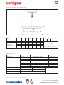
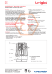
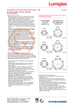
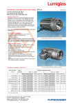
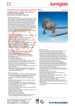
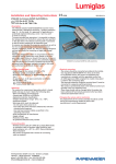
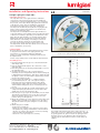
Installation and Operating Instructions
0093.030.00 a
Lumiglas sight glass wiper SW 1
•Important, please note:
The exploded view on the right shows the individual
components in their relevant positions. Parts numbered
11-16 have been works-assembled. Parts 3, 4, 5 ensure that the pressure of the wiper blades (14) against the underside
of the glass is correct. Prior to installation, it should be
checked that the sight glass is clean and undamaged.
The wiper unit should only be installed in a sight glass disc with a centric hole that has a diameter of 10.5 mm and
chamfered, undamaged edges.
The wiper unit is normally intended for glass thicknesses
of at least 10 mm to max. 30 mm and for operating pressures of between 2 and 6 bar, depending on the diameter of the sight glass disc and material. It is essential that the wiper blade holder (15) has a length that corresponds with the inside diameter of the fitting. If mounting is carried out
correctly, the distance between the wiper blade and
the edge of the flange should not be less than 1 mm.
The wiper blade holder and wiper blades can be shortened prior to installation, if necessary.
•Safety warning:
No metal parts of the wiper unit should have direct contact to any part of the surface of the sight glass disc due,
for instance, to eccentricity, missing or damaged
gaskets, etc. Only designated, undamaged parts should
be implemented.
If there is any doubt, please consult with the manufacturer.
Lumiglas wiper SW 1
mounted on a sight glass fitting to DIN 28120
•Assembly process:
1. Insert the O-ring (9) in the groove of the threaded bush with flange (10).
2. Push the flanged bush (10) into the centric hole of the sight glass disc.
3.Place the gasket (8) over the flanged bush (10) as a seal to the sight glass disc.
4. Screw the threaded sleeve (6) – keyways upward –
manually onto the flanged bush (10) so that the O-ring (9)
is slightly flattened against the glass (this is visible through the glass). It is also recommended to apply locking varnish into the threaded sleeve (6).
5.Pass the wiper arm spindle (11) – complete with the
pre-assembled parts (12 – 16) – through the flanged
bush (10) and rotate it slightly until the wiper blade
holder (15) fits snugly. Take care that the gaskets (12)
and the PTFE bearing bush (13) are not damaged in the process.
6. Place the spacer (4) with the journal downwards into the compression spring (5) and insert it over the wiper arm spindle (11) into the threaded sleeve (6).
7. Insert the spacer (3), longer side downwards, into the wiper arm spindle (11) until the lower of the two holes in the wiper arm spindle emerges. Fix the lower hole in this
position using a locating pin (2).
8. Mount the T-handle (1) on the upper end of the wiper arm spindle; align it carefully to the upper hole in the wiper arm spindle and fix it in place using the second locating
pin (2).
9. When using a lever handle:
- Remove the T-handle (1)
- Mount the lever handle on the upper end of the wiper arm spindle (11), taking consideration of the freewheel direction of rotation! The lettering on the free-running The flexible wiper blades (14) can be easily removed, e. g.
sleeve should point downwards.
when they are worn or damaged, by pressing the T-handle
- Attach the cover cap and press it on firmly.
(1) gently against the glass to release the spring pressure.
If gaskets (12 or 13) are damaged, they should only be
reworked by the manufacturer. Please consult with your
supplier.
F.H.Papenmeier GmbH & Co. KG · division Lumiglas
Talweg 2 · 58239 Schwerte · GERMANY
phone: +49-2304 205-0 · fax: +49-2304 205-206
[email protected] · www.lumiglas.de
• Dimensions for Lumiglas sight glass wiper SW 1
available as a special version
size
3 4 5* 6*7*8* 9 101112
nominal size of fittingDN
50 80 100 125150200250300350400
for port
d 1
80 100125 150175225
soda-lime or D
100 125150 175200250
borosilicate
s15/15115/15115/19115/19115/19115/25
sight glass disk
PN max…bar
6/616/615/614/614/412/41
d 2
77 97 122 147172222
wiper
* Combination with Lumistar luminaire possible; Lumistar luminaire 225
and Lumiglas USL and ESL luminaires only with lever handle!
1
on request
depends on diameter of glass disc and/or
on inside diameter of fitting, max. 460 mm
This data applies to borosilicate glass only
•Replacement parts
wiper blades
for sizes
L
Silicone rubber, part no.
PTFE, part no.
328.5
9468.062.00
2.9468.072.34
438.5
9468.063.00
2.9468.073.34
551
9468.064.00
2.9468.074.34
663.5
9468.065.00
2.9468.075.34
776
9468.066.00
2.9468.076.34
8101
9468.067.00
2.9468.077.34
9 to 12
seals + gaskets
for sizes
depends on diameter of glass disc in the fitting
ø x s
part no.
Viton-O-ring
(item 12 in diagram)
1 to 6
4 x 1
0862.019.00
Viton-O-ring
(item 9 in diagram)
1 to 6
12.37 x 2.62
0862.024.00
Subject to change without prior notice – Dimensions in mm unless otherwise stated.
F.H.Papenmeier GmbH & Co. KG · division Lumiglas
Talweg 2 · 58239 Schwerte · GERMANY
phone: +49-2304 205-0 · fax: +49-2304 205-206
[email protected] · www.lumiglas.de