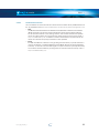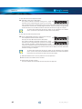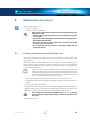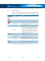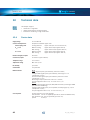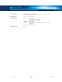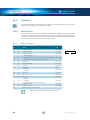
1
Operating Instructions
5“ Coin Validator
with BDTA/BACTA Interface
08.15 Hns/GS/Roe
BA_v2_eagle_parallel_EN_1-1
CPI Crane Payment Innovations GmbH | Zum Fruchthof 6 | 21614 Buxtehude | Germany
Web: [email protected] | www.cranepi.com | Phone: +49 (0) 41 61-729-0 | Fax: +49 (0) 41 61-729-115
parallel
TABLE OF CONTENTS
Table of contents
1
Revision protocol
7
2
About ...
8
2.1
2.1.1
2.1.2
About these operating instructions
Text conventions
Additional useful technical documentation
8
8
9
2.2
2.2.1
2.2.2
About the v2 eagle
The v2 eagle features
Models
2.2.2.1
2.2.2.2
2.2.2.3
Coin entry and return area
Internal 4-fold or 5-fold sorting mechanism
Parallel machine interface
9
9
10
10
10
11
3
Safety instructions
12
3.1
Proper use
12
3.2
Protecting persons and equipment
12
4
Design
13
4.1
4.1.1
4.1.2
Overview
13
v² eagle without sorting/with 5-fold in-line sorting mechanism 13
v² eagle with 4-fold sorting mechanism
14
4.2
4.2.1
4.2.2
Coin path (5-fold in-line sorter only)
v² eagle without sorting/
with 5-fold in-line sorting mechanism
v² eagle with 4-fold sorting mechanism
15
16
4.3
4.3.1
4.3.2
Product label
Model number decoding
Data block decoding
17
18
18
4.4
Label – switch functions/coin channel assignment
19
4.5
4.5.1
4.5.2
Switch blocks
Switch functions – switch block S1
Switch functions – switch block S2
20
20
20
BA_v2_eagle_parallel_EN_1-1
15
3
parallel
TABLE OF CONTENTS
4.6
Coin return lever
21
4.7
Status LED (only v² eagle with 4-fold sorter)
21
4.8
Interfaces
21
5
Function
22
5.1
Coin acceptance and coin channels
22
5.2
Memory blocks
23
5.3
Accepted coin sensor and sorting control
23
5.4
5.4.1
5.4.2
5.4.3
Transmission of coin values via coin pulses and coin signal lines
24
Multiple pulses
24
Coin pulse length
24
Tow assignments of the BACTA machine interface (standard and
binary mode)
25
5.4.3.1
5.4.3.2
25
25
5.5
Coin-in mech signal (CIMS) (option, not standard BACTA mode)
5.6
5.6.1
5.6.3
Coin inhibition/activation of narrow coin channels
26
Inhibiting all coins via the machine control system (common
inhibit)
26
Inhibiting individual coins/coin channels via the machine control
system (single inhibit)
26
Inhibiting individual coins/coin channels via the switch blocks 26
5.7
5.7.1
Sorting accepted coins (option)
Sorting principle of 5-fold in-line sorter (Ex8xPx. ..)
5.6.2
5.7.1.1
Sorting with NRI 4-way manifold (option)
25
27
27
28
5.7.2
Sorting principle of 4-fold sorter (Ex7xPx. ..)
29
5.7.2.1
5.7.2.2
Sorting with Money Controls 4-way manifold
Sorting with active Money Controls 8-way manifold
30
31
5.7.3
5.7.3.1
5.7.3.2
4
Binary mode
Standard mode
Sorter override for tube-full signal via ...
... Single inhibit lines of BDTA interface
... Sorter override interface (only BACTA)
32
32
32
5.8
Teach mode (option)
32
5.9
5.9.1
5.9.2
Manipulation detection (option)
Foul signal (only v² eagle BACTA)
String recognition
33
33
33
BA_v2_eagle_parallel_EN_1-1
parallel
TABLE OF CONTENTS
6
Start-up
34
7
Operation
36
7.1
7.1.1
7.1.2
Selecting the memory block ...
... using the switch block on the coin validator
... via machine control (option, only BDTA interface)
36
36
36
7.2
7.2.1
7.2.2
Inhibiting coins/activating narrow coin channel
Inhibit functions – switch block S1
Inhibit functions – switch block S2
37
37
37
7.3
Teaching coin channels in teach mode (optional)
39
8
Maintenance and service
41
8.1
Cleaning measurement and validation area
41
8.2
Troubleshooting
43
9
What subsequent settings can be made?
44
9.1
9.1.1
9.1.2
Service and configuration tools
PC configuration software heartbeat
On-site service tool HENRI+
44
44
44
9.2
Which device functions can be set?
44
10
Technical data
46
10.1
Device data
46
10.2
10.2.1
Interfaces
BDTA interface
48
48
10.2.1.1
10.2.1.2
10.2.1.3
10.2.2
10.2.2.1
10.2.2.2
10.2.2.3
10.2.3
10.2.4
BA_v2_eagle_parallel_EN_1-1
BDTA pin assignment
BDTA interface description
BDTA connection diagram
BACTA interface
BACTA pin assignment, binary mode
BACTA pin assignment, standard mode
BACTA interface description
Sorter override interface (only BACTA)
v² eagle – 8-fold manifold (option, only BACTA 4-fold sorter)
48
49
49
50
50
51
51
52
52
5
6
10.3
10.3.1
10.3.2
10.3.3
Accessories
Front plates
Manifolds/sorters
Service tools
53
53
54
55
11
Index
56
BA_v2_eagle_parallel_EN_1-1
parallel
1
REVISION PROTOCOL
Revision protocol
Version
Revision
_1-0
First official version
_1-1
BA_v2_eagle_parallel_EN_1-1
Chapters/sections concerned
• Revised current consumption values
• 10.1 "Device data"
• Coin path for 4-fold sorter
• 4.2 "Coin path"
• Revised product label
• 4.3 "Product label"
• Order numbers for accessories updated
• 10.3 "Accessories"
7
parallel
ABOUT ...
2
About ...
This chapter is intended to provide a general overview of the advantages and options of the
coin validator v2 eagle with parallel interface. The first section, however, is designed to help you
navigate easily within these operating instructions.
2.1
About these operating instructions
These operating instructions describe the design and operation of the electronic 5" coin validator
v2 eagle with parallel BDTA or BACTA interface. Afterwards, chapters 6 and 7 explain the necessary
steps for starting up and operating the coin validator. Chapter 7 describes how to clean the coin
validator and remedy the cause of any malfunction.
Chap. 10 "Technical data" and the appended "Index" reduce the search for specific explanations.
2.1.1
Text conventions
To make it easier for you to navigate within these operating instructions and to operate the
device, the following accentuations were made in the text:
Safety instructions which you must observe in order to protect operators
and equipment.
Special notes intended to facilitate the use of the coin validator.
At the beginning of each chapter you will find a short "guide" which summarizes
the contents of the chapter.
Device functions which are set or prepared by the manufacturer according
to customer specifications and can be set or changed using our service and
configuration tools (cf. Chap. 9 What subsequent settings can be made?, p. 44).
8
1 2 3 ...
Requests to perform an action are numbered in a different typeface.
[Fig. 1/2]
Cross-reference to an illustration. The number preceding the slash indicates the
number of the figure, the number following the slash is the number of the item
in the figure.
BA_v2_eagle_parallel_EN_1-1
parallel
2.1.2
ABOUT ...
Additional useful technical documentation
Apart from the operating instructions you already have, further documentation is available for
the v2 eagle, e.g. for configuration or spare part lists. All documentation can be downloaded
from the Crane Payment Innovations website (www.cranePI.com, Support) as pdf.
2.2
About the v2 eagle
The v2 eagle coin validator with parallel BDTA/BACTA interface in the standardized 5“ format
uses the patented multi-frequency technology (MFT) for reliable coin validation. Communication
with the vending machine control system takes place via the 16-pin BDTA or the 17-pin BACTA
connector. Due to its compact design the v2 eagle is ideally suited for gaming, vending and
service machines.
For coin acceptance the coin validator has 32 coin channels which – divided into 2 x 16 coin
channels – can be managed in two memory blocks with different coin configurations and
selected individually.
Depending on the application, the coin validator can optionally be equipped with an internal
4-fold or 5-fold sorter.
To be able to react as quickly as possible to new false coins and to make your individual settings,
the coin validator can be configured on site in the machine using a service tool or in the workshop
via a PC programming station.
Any coins or tokens not taken into account by the manufacturer can be programmed in the optional
teach mode directly on the coin validator without any configuration software by inserting the coins.
2.2.1
The v2 eagle features
• Reliable acceptance of genuine coins and rejection of false coins due to MFT multiple
sensing of the coins inserted and evaluation of 24 measuring parameters
• Operating and manipulation safety provided by optical accepted coin sensors and sorting
control in the coin validation and coin outlet area
• Acceptance speed of two coins per second
• 32 coin channels managed in two independently configured and individually selectable
memory blocks (2 x 16 coin channels)
• Service interface for PC programming station or on-site service tool
• Flash technology for easy and time-saving firmware updates (CXflash))
• Options
– teach mode for eight coin channels
– string sensor
– top or front entry, front or bottom return
– front plate
– 4-fold or 5-fold sorting mechanism
– passive 4-way both or active 8-way manifold for 4-fold sorting mechanism
– various return levers depending on machine type
BA_v2_eagle_parallel_EN_1-1
9
parallel
ABOUT ...
2.2.2
Models
The v2 eagle is available in different models. They mainly differ
• in the coin entry and return area
• in the sorting mechanism and
• in the machine interface.
2.2.2.1
Coin entry and return area
• Top entry and bottom return (E1xxPx. ..)
The coin is inserted into the device from the top and returned, if not
accepted, via the return area at the bottom.
• Front entry and bottom return (E3xxPx. ..)
The coin is inserted into the device from the side and returned, if not
accepted, via the return area at the bottom. The coin validator with
front entry generally has an NRI front plate fitted to the left-hand side
of the device (cf. Chap. 10.3.1 Front plates, p. 53). However, this model is
also available without front plate.
• Front entry and front return (E4xxPx. ..)
The coin is inserted into the device from the side and returned, if not
accepted, via the return area also located on the side. The coin validator
with front entry generally has an NRI front plate fitted to the left-hand
side of the device (cf. Chap. 10.3.1 Front plates, p. 53). However, this model
is also available without front plate.
2.2.2.2
Internal 4-fold or 5-fold sorting mechanism
In order to sort the accepted coins into the cash-box or e.g. change tubes or hoppers, the v2 eagle
can optionally be equipped with an internal 5-fold sorting mechanism (cf. Chap. 5.7 Sorting accepted
coins (option), p. 27):
• 4-fold sorter (Ex7xPx. ..)
• 5-fold in-line sorter (Ex8xPx. ..)
• Single cash-box chute out of 5-fold in-line sorter (no sorting mechanism)
(Ex1xPx. ../Ex2xPx. ../Ex3xPx. ../Ex4xPx. ../Ex5xPx. ..)
10
BA_v2_eagle_parallel_EN_1-1
parallel
2.2.2.3
ABOUT ...
Parallel machine interface
The coin validator communicates with the machine control via either the 16-pin BDTA interface or
the 17-pin BACTA interface (cf. Chap. 5.4 Transmission of coin values via coin pulses and coin signal lines, p. 24):
• BDTA
The Bundesverband der Deutschen Tabakwaren-Großhändler und Automatenaufsteller
(BDTA) (association of German tobacco wholesalers) determined the DTG standard 2
for the electrical interface to the vending machine. This standard includes the specification of the supply voltage, the coin signal lines, inhibit functions and the return signal (cf.
Chap. 10.2.1 BDTA interface, p. 48). In addition to further standardization requirements for validators the measurement quality of validators is also specified.
• BACTA
For AWP and SWP coin validators in the gambling machine industry a parallel interface is
used as provided for in the British BACTA standard (British Amusement Catering Trade Association). To transmit coin and inhibit signals a 17-pole connector is primarily used today.
The connector features different pin assignments for standard mode and binary mode (cf.
Chap. 10.2.2 BACTA interface, p. 50).
BA_v2_eagle_parallel_EN_1-1
11
SAFETY INSTRUCTIONS
3
parallel
Safety instructions
Before starting up the device for the first time, please read these instructions and in particular
the safety instructions carefully at least once. This is to ensure that you have understood the
contents of this manual and how to operate the coin validator.
3.1
Proper use
The electronic 5“ coin validator v2 eagle with parallel BDTA or BACTA interface is intended for use
in gaming, vending and service machines with parallel BDTA or BACTA interface and is designed
to check the coins inserted into the machine for specific properties and to accept (and sort) or
reject them. Use the coin validator exclusively for this purpose. Under no circumstances can the
manufacturer be held liable for any damage or loss resulting from improper use of the device.
The coin validator has been built in accordance with state-of-the-art standards and the recognized
safety rules. Nevertheless, this equipment can constitute a source of danger. Please observe
therefore the following safety instructions.
3.2
Protecting persons and equipment
The coin validator must only be connected by a trained electrician.
Use the coin validator only in accordance with its proper use. Under no circumstances
can the manufacturer be held liable for any damage or loss resulting from improper use
of the device.
The coin validator PCB is fitted with components which may be damaged beyond repair
by electrostatic discharges. Please observe the handling instructions for components
exposed to the risk of electrostatic discharge.
Select the correct voltage for the coin validator (see label).
Pay attention to correct electrical bonding in the machine.
Never pull the connecting cable of the coin validator from the machine when a voltage
is applied.
Pull the mains plug of the machine before installing, cleaning or removing the coin validator.
Please consult Crane Payment Innovations ind Buxtehude if you intend to make additions
or modifications to the device that go above and beyond the modifications described here.
Keep water and other liquids away from the coin validator.
Please dispose of the device correctly at the end of its service life.
We reserve the right to make technical modifications to the device which are not covered
by these instructions!
12
BA_v2_eagle_parallel_EN_1-1
parallel
4
DESIGN
Design
This chapter describes
• the main parts the v2 eagle consists of, and
• all parts required for the operation of the coin validator.
4.1
Overview
of the top entry model
• without sorting mechanism or with 5-fold in-line sorting mechanism
• with 4-fold sorting mechanism
4.1.1
v² eagle without sorting/with 5-fold in-line sorting mechanism
1
2
8
3
14
4
13
12
5
11
10
1
8
2
3
4
5
6
9
v² eagle BDTA
8
v² eagle BACTA
urn
et
Fig. 1: Design – v2 eagle without sorting/with 5-fold in-line sorting mechanism R
1 Coin insert funnel (front entry model, open on the
side (cf. Chap. 4.2 Coin path (5-fold in-line sorter only), p. 15)
7
8 Mounting stud
9 Interface – service/configuration
2 Coin return lever (option)
10 Label
3 Flight deck
11 Interface – sorter override (BACTA)
4 Locking lever for sorting cover
12 Interface – machine (BDTA/BACTA)
5 Closing device for flight deck
13 Switch blocks
6 Coin outlet – cash box/sorting
14 Label – Switch block/coin channel assignment
7 Coin outlet – return area (cf. Chap. 4.2 Coin path (5-fold
(cf. Chap. 4.4 Label – switch functions/coin channel assignment, p. 19)
in-line sorter only), p. 15)7
BA_v2_eagle_parallel_EN_1-1
13
parallel
DESIGN
4.1.2
v² eagle with 4-fold sorting mechanism
1
2
9
3
16
15
4
14
5
6
13
12
11
B
9
A
10
7
v² eagle BACTA
D
C
v² eagle BDTA
9
urn
Ret
8
Fig. 2: Design – v2 eagle with 4-fold sorting mechanism
1 Coin insert funnel
10 Interface – service/configuration
2 Coin return lever
11 Interface – sorter override (BACTA)
3 Flight deck
12 Interface – machine (BDTA/BACTA)
4 Label
13 Interface – 8-fold sorting adapter (option)
5 Locking lever for sorting cover
14 Switch blocks
6 Closing device for flight deck
15 Label – Switch block/coin channel assignment
7 Coin outlet – cash-box/sorting
8 Coin outlet – return
(cf. Chap. 4.4 Label – switch functions/coin channel assignment, p. 19)
16 Status LED
9 Mounting stud
14
BA_v2_eagle_parallel_EN_1-1
parallel
4.2
Coin path (5-fold in-line sorter only)
4.2.1
v² eagle without sorting/
with 5-fold in-line sorting mechanism
Front entry with bottom return
DESIGN
Top entry
... front return
Fig. 3: Coin path for top and front entry version of the v² eagle without sorting or with 5-fold in-line sorting
BA_v2_eagle_parallel_EN_1-1
15
parallel
DESIGN
4.2.2
v² eagle with 4-fold sorting mechanism
Top entry
Front entry with bottom return
... front return
Fig. 4: Coin path for top and front entry version of the v² eagle
with 4-fold sorting mechanism
16
BA_v2_eagle_parallel_EN_1-1
parallel
4.3
DESIGN
Product label
The label of the coin validator [Fig. 1/10] [Fig. 2/4] contains all data defining the device such as
device number and type, operating voltage and customer-specific currency and coin programming:
1
2
3
0010118880/0010/0004
13
12
11
10
E181P4.00/0.S
E0P40-EU---20000A
xxxxx/yyyyyyyyyyyyyyyy
FW: 445-04.46
|BDTA|
Class 2
12-24V DC
EUR -,10 / -,20 / -,50 / 1,- / 2,-
4
5
6
7
8
EUR -,10 / -,20 / -,50 / 1,- / 2,Crane Payment Innovations GmbH
+49 (0) 41 61/729-0 | [email protected]
MADE IN GERMANY
06/15
9
Fig. 5: Product label
1 Bar code
2 Order number (10-digit),
item number/order (4-digit),
device serial number (4-digit)
7 Order number /Customer material number
(option)
8 Firmware number/version
9 Date of manufacture
3 Device type
10 Coin programming – memory block B
4 UL control circuit classification:
Class 2 (UL 508A §2.7) = Control circuit
with limited power
11 Coin programming – memory block A
5 Nominal voltage
12 Data block number/revision A–Z (cf.
6 Machine interface
(if DIL switch S1 set to ON)
(if DIL switch S1 set to OFF)
Chap. 4.3.2 Data block decoding, p. 18)
13 Model number (cf. Chap. 4.3.1 Model number
decoding, p. 18)
BA_v2_eagle_parallel_EN_1-1
17
parallel
DESIGN
4.3.1
Model number decoding
E178C3.00/0.EPS
0010118880/0010/0004
E178C3.00/0.EFPS
E0C30-EUEU-22002A
xxxxx/yyyyyyyyyyyyyyyy
FW: 445-04.46
|ccTalk|
Class 2
12-24V DC
EUR -,10 / -,20 / -,50 / 1,- / 2,EUR -,10 / -,20 / -,50 / 1,- / 2,Crane Payment Innovations GmbH
+49 (0) 41 61/729-0 | [email protected]
MADE IN GERMANY
06/15
EXXXXX.XX/X.XXX
Options – Diverter interface (s2 HSD), Encryption, Hardness sensor, Jam sensor, Opto sensor, P = Write
protection, String detection, Water protected
Options
Manufacturing process – internal option code & revision
Machine interface – C0 = ccTalk, C3 = ccTalk, SR5-compatible, C4 = ccTalk ACMI,#
P4 = BDTA, P5 = BACTA, S0 = S1
Machine interface
Coin return lever – 0 = no lever 1–8 = rf. table
Sorting – 1..5 = without sorting with fixed cash box chute 1..5, 7 = 4-fold sorter, 8 = 5-fold in-line sorter, 9 = 5-fold cross-way sorter
Equipment
Coin entry/outlet – 1 = Top entry, 3 = Front entry/bottom return, 4 = Front entry & return
v2 family – Eagle
Coin return lever #
4.3.2
1
2
3
4
5
6
8
Data block decoding
0010118880/0010/0004
E178C3.00/0.EFPS
E0C30-EUEU-22002A
xxxxx/yyyyyyyyyyyyyyyy
FW: 445-04.46
|ccTalk|
Class 2
12-24V DC
E0C30-EUEU-22002A
EUR -,10 / -,20 / -,50 / 1,- / 2,EUR -,10 / -,20 / -,50 / 1,- / 2,-
Crane Payment Innovations GmbH
+49 (0) 41 61/729-0 | [email protected]
MADE IN GERMANY
06/15
EXXXX-XXXX-XXXXXX
Data block revision A–Z
3-digit consecutive number
Configuration
Write protection – 0 = No protection, 1 = ACMI, 2 = VDAI
Memory block/Coin channels – 1 = 1 x 32 coin channels, 2 = 2 x 16 coin channels
Second currency – XX = First 2 digits of ISO4217 currency code, -- = no 2nd currency, +2 = 2nd & 3rd currency,
+3 = 2nd, 3rd & 4th currency
Main currency – XX = First 2 digits of ISO4217 currency code (EU = Euro, CH = Swiss franc, US = US dollar)
Currency
Hardware relevant to coin acceptance – 0 = Top entry, 2 = Front entry
Machine interface – C0 = ccTalk, C3 = ccTalk, SR5-compatible, C4 = ccTalk ACMI, P4 = BDTA, P5 = BACTA, S0 = S1
Measurement variant – V0, V1
Hardware
v family – Eagle
2
18
BA_v2_eagle_parallel_EN_1-1
parallel
4.4
DESIGN
Label – switch functions/coin channel assignment
In order to enable easy operation of the coin validator
there is a label [Fig. 1/14] [Fig. 2/15], on the rear
of the device briefly showing the functions of the
DIL switches at the bottom (cf. Chap. 4.5 Switch blocks,
p. 20) above these the coin channels assigned to
the individual coins programmed in memory block
A and B (cf. Chap. 5.2 Memory blocks, p. 23):l
Normal channel (No.)
Narrow channel (No.)
Super narrow channel (No.)
The data block number on the top
ensures clear allocation to the device
and product label.
After configuration, we recommend
that you change all labels on the
product to reflect the new settings
or that you make a note of the new
settings in a different form for the
workshop and the place of use.
E0P40-EU---20000A
Block A
EUR -,05
EUR -,10
EUR -,20
EUR -,50
EUR 1,EUR 2,TK 1794
01
02
03
04
05
06
13
07
08
09
10
11
12
--
--------
Block B
Block B
–
Inhibit channel 1..8
S1.1–10
Open channel 1..8
–
Block A
–
TEACH Mode
Inhibit channel 9..16
S2.1–10
Open channel 9..16
NORMAL Mode
–
Fig. 6: Label – switch functions/coin
channel assignment
BA_v2_eagle_parallel_EN_1-1
19
parallel
DESIGN
4.5
Switch blocks
The coin validator has two switch blocks [Fig. 1/13] [Fig. 2/14] with ten DIL switches each
(S1.1-10 and S2.1–10) on the rear of the device. The DIL switches can be used to set certain
device functions:
To find out how to set the individual functions with the help of the switch block, refer to Chap. 7
Operation, p. 36
On the rear of the device you will find a brief description of the individual switch
functions.
4.5.1
Switch functions – switch block S1
Function
OFF
ON
S1.1
Coin channel 1
accepts
inhibited
S1.2
Coin channel 2
accepts
inhibited
S1.3
Coin channel 3
accepts
inhibited
ON
S1.4
Coin channel 4
accepts
inhibited
OFF
S1.5
Coin channel 5
accepts
inhibited
S1.6
Coin channel 6
accepts
inhibited
S1.7
Coin channel 7
accepts
inhibited
S1.8
Coin channel 8
accepts
inhibited
S1.9
not used
–
–
Memory block
A
B
DIL switch
S1.10
4.5.2
Switch functions – switch block S2
DIL switch Function
ON
S2.1 Coin channel 9
accepts
inhibited
S2.2 Coin channel 10
accepts
inhibited
S2.3 Coin channel 11
accepts
inhibited
S2.4 Coin channel 12
accepts
inhibited
S2.5 Coin channel 13
accepts
inhibited
S2.6 Coin channel 14
accepts
inhibited
S2.7 Coin channel 15
accepts
inhibited
S2.8 Coin channel 16
accepts
inhibited
S2.9 Operating mode
normal mode
teach mode
–
–
S2.10
20
OFF
not used
ON
OFF
BA_v2_eagle_parallel_EN_1-1
parallel
4.6
DESIGN
Coin return lever
The return lever [Fig. 1/2] [Fig. 2/2] on the top of the device is operated using the return button
on the machine when coins which have been inserted are to be returned or e.g. a jam caused
by coins which have become stuck needs to be removed. Actuation of the return lever opens the
measurement and validation area of the coin validator so that all objects in the coin validator
are directed to the return area.
The v2 eagle can be equipped with various return levers, depending on the dimensions of the
machine (cf. Chap. 4.3.1 Model number decoding, p. 18).
4.7
Status LED (only v² eagle with 4-fold sorter)
The coin validator is equipped with a red status LED [Fig. 2/16] on the rear side to indicate the
operating state of the device:
Flashing frequency
4.8
Significance
Once per second
Device connected, no fault
Three times per second
Error, no coin acceptance
Interfaces
For details of the machine and sorter interfaces [Fig. 1/11, 12] [Fig. 2/11–13] please refer to
Chap. 10.2 Interfaces, p. 48.
BA_v2_eagle_parallel_EN_1-1
21
parallel
FUNCTION
5
Function
This chapter describes how the coin validator works:
• Coin acceptance and coin channels
• Memory blocks
• Accepted coin sensor and sorting control
• Coin pulses and signal lines
• Coin inhibition/activation of narrow coin channels
• Sorting accepted coins (option)
• Teach mode (option)
• Manipulation detection (option)
5.1
Coin acceptance and coin channels
For coin acceptance the coin validator has 32 "memory slots" to which up to 32 different coin
types or tokens can be assigned. These "memory slots" are called coin channels. The acceptance
band of one coin type/token is assigned to each coin channel and the respective coin type/
token is accepted in this channel.
To enable reliable rejection of false coins, channels with a narrow or even very narrow acceptance
band are frequently set up for a coin type in addition to the normal coin channel. The limit values
of these coin channels are closer to one another so that false coins with similar measured values
are rejected, if the normal channel is inhibited (cf. Chap. 7.2 Inhibiting coins/activating narrow coin channel,
p. 37). However, narrow and super-narrow coin channels also have a lower acceptance rate.
In addition, it is possible to assign coins with different measured values but identical coin values
to different coin channels. In this way the coin validator can accept e.g. old and new coins of
the same denomination.
In addition to the acceptance band of a coin type, further coin information which defines further
processing of the coin after its acceptance is assigned to a coin channel: e. g. the coin signal
line and pulse number or sorting information for a sorting device.
Since in most cases not all coin channels are assigned by customized factory programming,
further coin types and the desired information can be assigned to these free channels at any
time using the NRI configuration and service tools. Existing configurations can be changed.
Eight coin channels are intended to be used for the teach mode. In these teach channels new
tokens/coin types can be taught also without configuration and service tools, directly on the coin
validator using the switch blocks. I.e. a new coin or token is assigned to a channel (cf. Chap. 5.8
Teach mode (option), p. 32).
22
BA_v2_eagle_parallel_EN_1-1
parallel
5.2
FUNCTION
Memory blocks
The v2 eagle manages two separately programmed (memory) blocks A and B (cf. Chap. 4.3 Product
label, p. 17). 16 coin channels with different coin types (also currencies), sorting information
etc. can be assigned to each block. Only one block at a time can be active and used for coin
measurement and further coin processing. You can use the switch block on the device to select
the desired block (cf. Chap. 7.1 Selecting the memory block ..., p. 36).
On request, the respective other memory block can also be loaded via
the machine. This requires that the v² eagle is equipped with the BDTA
interface and has been programmed in the factory in such a way that the
single inhibiting line 6 (pin 4) can no longer be used for inhibiting but for
block switching. In this case, coin line 1 (pin 13) is not only available for
transmitting coin pulses, but also for the feedback to block switching (cf.
Chap. 7.1 Selecting the memory block ..., p. 36) and (cf. Chap. Product certifications
C
E
UL, p. 47).
5.3
Accepted coin sensor and sorting control
To ensure that accepted coins actually arrive in the cash-box or sorting device and that
acceptance has not been tampered with, an accepted coin sensor (light barrier) and a
sorting control (light barrier) check whether the inserted coin drops unhindered through the
coin outlet towards the cash-box or sorting device. Only when the coin has passed these
checking devices a coin signal or, in case of manipulation, an error code is transmitted to the
machine (cf. Chap. 5.4 Transmission of coin values via coin pulses and coin signal lines, p. 24) and (cf. Chap. 5.9
Manipulation detection (option), p. 33).
BA_v2_eagle_parallel_EN_1-1
23
parallel
FUNCTION
5.4
Transmission of coin values via coin pulses and coin signal
lines
By default each coin accepted by the coin validator sends a pulse to the machine control via
the coin signal line assigned to it. A pulse signals to the machine control that a coin has been
accepted.
Six or, in case of the binary BACTA mode, four coin signal lines are available to the coin validator.
Depending on the signal line activated the machine knows the coin denomination (coin value)
concerned.
Assignment of coin denomination and coin signal line is determined by customized factory
programming.
In case of coin validators with BDTA interface or BACTA devices in the binary
mode, you can also assign a certain combination of signal lines, i.e. several
signal lines, to a coin type for differentiation.
5.4.1
Multiple pulses
If the number of coin denominations programmed exceeds the number of signal lines available,
several coin pulses (multiple pulses, 255 max.) per coin can be assigned to the coin denominations,
so that the machine distinguishes the coin denominations not by the signal line but by the
number of pulses. In this case a multiple of a small coin is assigned to higher value coins, e.g.
if a €2 coin is inserted, two coin pulses would be sent to the vending machine control via the
coin signal line assigned to the €1 coin.
The number of coin pulses is determined by customized factory programming.
By default the pulse-to-pause ratio is programmed 1:1. However, it can also be programmed
with a longer pause of 300 ms.
5.4.2
Coin pulse length
By default the coin pulse length is programmed to 100 ms. On request, however, it can be
programmed shorter, e.g. for multiple pulses (possible programming: 20–300 ms).
24
BA_v2_eagle_parallel_EN_1-1
parallel
5.4.3
FUNCTION
Tow assignments of the BACTA machine interface (standard and
binary mode)
In order to be able to run the parallel or binary mode, two different functions are assigned to the
17 pins of the BACTA machine interface on the rear of the coin validator, except for the select
line (pin 8). This double assignment enables the coin validator to operate in parallel or binary
mode with a special pin assignment, depending on how the machine control system switches
the select line (cf. Chap. 10.2.2 BACTA interface, p. 50).
5.4.3.1
Binary mode
The binary mode is characterised by tamper-proofness which prevents the credit from being
increased through improper connection or aimed manipulation. The coin signal is only transmitted
to the machine if the so-called strobe line is active and the checksum is correct.
The coin validator operates in binary mode if it is connected to the machine via a 17-pole
connecting cable and if the machine control system switches the select line to "low".
5.4.3.2
Standard mode
The coin validator operates in standard if the machine control system switches the select line
to "high".
5.5
Coin-in mech signal (CIMS) (option, not standard BACTA
mode)
The coin validator can optionally send a 100 ms signal, as soon as a coin has reached the
measuring area (CIMS = Coin-In Mech Signal).
The coin signal line(s) to transmit the CIMS is (are) determined by customized factory programming
(default: coin lines 1–3).
The CIMS is sent time-delayed if the coin lines are just sending a pulse for coin
acceptance. Therefore the signal is not always synchronous with the coin position.
BA_v2_eagle_parallel_EN_1-1
25
parallel
FUNCTION
5.6
Coin inhibition/activation of narrow coin channels
If coins are no longer to be accepted for payment on the machine you can either
• inhibit coin acceptance completely,
• inhibit all coin channels of a certain coin to ensure that this coin is no longer accepted, or
• inhibit the normal coin channel of a certain coin so that this coin is accepted only in the
narrow channel.
5.6.1
Inhibiting all coins via the machine control system (common inhibit)
The machine can inhibit coin acceptance via the common inhibit signal line of the BDTA interface.
In this case the coin validator does not accept any coins (cf. Chap. 10.2 Interfaces, p. 48).
In case of BACTA coin validators, all inhibit lines assigned to the coins must be
activated.
5.6.2
Inhibiting individual coins/coin channels via the machine control
system (single inhibit)
For inhibiting a coin six single inhibit signal lines are available to the machine to
• inhibit all coin channels of a certain coin, e.g. if there is no more change in an external
payout unit or in case of high fraud hazard.
• inhibit the normal coin channel of a certain coin so that this coin is accepted only in the
narrow channel (cf. Chap. 10.2 Interfaces, p. 48).
The coin type or coin channel and the signal line via which it is to be inhibited are determined
by customized factory programming.
5.6.3
Inhibiting individual coins/coin channels via the switch blocks
As an alternative to inhibition via the control system you can inhibit individual coin channels on
site via the switch blocks on the coin validator.
Chap. 7.2 Inhibiting coins/activating narrow coin channel, p. 37, describes how to inhibit these coin channels
26
BA_v2_eagle_parallel_EN_1-1
parallel
5.7
FUNCTION
Sorting accepted coins (option)
To direct accepted coins either to the cash-box or an external sorting device, e.g. change tubes
or hoppers, the coin validator can be equipped with a 5-fold in-line sorter or a 4-fold sorter
at the coin outlet. The chutes are controlled via a flap sorting system using three solenoids.
In this section you learn all about the principle of
• In-line sorting
– without optional manifold
– with optional manifold
• 4-fold sorting
– without manifold
– with 4-fold or 8-fold manifold
• Controlling a cash-box/override sorting chute (option)
5.7.1
Sorting principle of 5-fold in-line sorter (Ex8xPx. ..)
The individual coin types can be distributed to the five chutes arranged behind one another
independent of their dimensions. Each chute can be
defined as cash box chute.
Which coin is sorted into which of the up to five chutes is
determined by customized factory programming.
Use the single inhibit signal lines of the
BDTA interface for external sorting control:
If the same coin is configured in two
different coin channels with identical
acceptance bands (in the factory or by
heartbeat), you can assign different
sorting chutes to the two coin channels.
If, in addition, different single inhibit signal
lines are assigned to the two channels, the
machine can sort the coin via the single
inhibit signal lines into either of the two
sorting chutes or into both.
1
urn
Ret
Fig. 7: Sorting chutes 1–5 of
in-line sorting system
BA_v2_eagle_parallel_EN_1-1
27
2
3
4
5
parallel
FUNCTION
5.7.1.1
Sorting with NRI 4-way manifold (option)
For the purpose of splitting-up and for better transport
of the sorted coins you have the option of an NRI 4-way
manifold which can be screwed to the coin validator from
the bottom. This manifold is primarily used in AWP and
SWP slot machines.
If the sorting adapter is installed four sorting chutes are
available to you (cf. Chap. 10.3.2 Manifolds/sorters, p. 54).
Which coin is sorted into which of the up to four chutes is
determined by customized factory programming.
The following table shows which manifold chute corresponds
to which coin validator chute:
Manifold chute
v2 eagle sorting chute
A
3
B
2
C
1
D
5
urn
Ret
Fig. 8: Sorting chutes A–D of
NRI manifold
28
BA_v2_eagle_parallel_EN_1-1
parallel
5.7.2
FUNCTION
Sorting principle of 4-fold sorter (Ex7xPx. ..)
The individual coin types can be distributed to the four
sorting chutes independent of their dimensions. Each
chute can be defined as cash box chute.
D
C
A
B
Which coin is sorted into which of the chutes is determined
by customized factory programming or set via the
machine control system. Default setting: chute D
urn
Ret
Fig. 9: Sorting chutes of
4-fold sorting system
BA_v2_eagle_parallel_EN_1-1
29
parallel
FUNCTION
5.7.2.1
Sorting with Money Controls 4-way manifold
For the purpose of splitting-up and for better transport
of the sorted coins you have the option of a Money
Controls 4-way manifold which can be screwed to the
coin validator from the bottom. This adapter is primarily
used in AWP and SWP slot machines.
If the sorting adapter is installed four sorting chutes are
available to you (cf. Chap. 10.3.2 Manifolds/sorters, p. 54).
Which coin is sorted into which of the up to four chutes
is determined by customized factory programming.
The following table shows which manifold chute
corresponds to which coin validator chute:
v² eagle sorting chute
A
A
B
B
C
C
D
D
D
C
A
B
Manifold chute
urn
Ret
Fig. 10: Sorting chutes A–D of Money Controls
4-way manifold
30
BA_v2_eagle_parallel_EN_1-1
parallel
5.7.2.2
FUNCTION
Sorting with active Money Controls 8-way manifold
For applications which require 8-fold sorting it is
possible to mount a Money Controls 8-way manifold
below the coin validator in the vending machine (cf.
Chap. 10.3.2 Manifolds/sorters, p. 54). This active 8-way
sorter splits up the four sorting chutes of the coin
validator into pairs of two each.
Which coin is sorted into which of the up to eight
chutes is determined by customized factory
programming.
The following table shows which manifold chute
corresponds to which coin validator chute:
Manifold chute
A
a
B
b
C
c
D
A
B
C
D
C
urn
Ret
D
d
B
c
A
b
a
d
v2 eagle sorting chute
Fig. 11: Sorting chutes of Money Controls
8-way manifold
BA_v2_eagle_parallel_EN_1-1
31
parallel
FUNCTION
5.7.3
Sorter override for tube-full signal via ...
5.7.3.1
... Single inhibit lines of BDTA interface
If the machine control shall sort coins into the cash box chute or into an override sorting chute
when the external sorting device sends a "full" signal, the coin validator can be programmed in
the factory in such a way that, depending on the status of the single inhibit signal line 6 (pin 4)
(high/low), the single inhibit signal lines 1–5 either
• inhibit coins by default (single inhibit signal line 6 = low, single inhibit lines 1–5 = high) or
• sort the coins assigned to the single inhibit signal lines into the cash box (single inhibit
signal line 6 = high, single inhibit signal lines 1–5 = high) (cf. Chap. 10.2.1 BDTA interface,
p. 48).
Cash box/override sorting path
The machine alternatively sends inhibit and sort signals to the coin validator via the single inhibit
signal lines if no coin is accepted. The information is stored by the coin validator whenever the
signal is present for at least 10 ms.
If the cash box chute is controlled via the single inhibit signal line 6, only five
instead of six signal lines are available for coin acceptance and inhibiting.
5.7.3.2
... Sorter override interface (only BACTA)
Via the 10-pole sorter override interface on the device rear side, the coin validator can receive
a tube-full signal for the four coin validator sorting chutes 1, 2, 3 and 5 or A, B, C, D, or for the
four manifold chutes A, B, C and D in order to enable steering of the coins to be sorted into a
full payout unit to the cash box or any alternative payout unit (cf. Chap. 10.2.3 Sorter override interface
(only BACTA), p. 52).
The sorting destination in case of "tube full" depends on the respective sorting equipment and
configuration.
5.8
Teach mode (option)
If the v2 eagle has been programmed accordingly in the factory, coin channels can be taught in
the teach mode without configuration software via the switch block on the coin validator, i. e.
a new token or coin is assigned to a coin channel. The new acceptance band is generated by
inserting the tokens/coins. It is not necessary to remove the coin validator from the machine
for this purpose. The last eight coin channels 9–16 (= teach channels) of the activated memory
block are available for teaching (cf. Chap. 7.3 Teaching coin channels in teach mode (optional), p. 39).
32
BA_v2_eagle_parallel_EN_1-1
parallel
5.9
FUNCTION
Manipulation detection (option)
In case manipulation is detected while a coin is being accepted the coin validator emits a foul
signal and a string signal as an option.
5.9.1
Foul signal (only v² eagle BACTA)
The coin validator reports a manipulation of the acceptance gate by transmitting a foul signal
(pulse length: at least 600 ms) via all signal lines in the standard mode (in the binary mode: via
all signal lines except for the strobe line). Coin acceptance is inhibited.
5.9.2
String recognition
To ensure that no coins suspended from a string can be inserted into the coin validator or that
the acceptance gate cannot otherwise be tampered with, the coin validator can be equipped
with an optical string sensor (cannot be retrofitted) in the acceptance area which recognizes
both tight and loose strings.
The construction of the acceptance gate (dismounted in figure) makes
the string go through the light beam between the two optical
cal
sensors. If the acceptance gate is completely closed, the string
g
changes the light signal. If the acceptance gate is slightly
open (tight string), the light beam is directly interrupted by
flag on the acceptance gate.
If the sensor recognizes a string, coin signal line 1 or 6
of the BDTA interface sends a string signal, or the BACTA
interface sends a foul signal (cf. Chap. 5.9.1 Foul signal (only v² eaglee
BACTA), p. 33) to the machine, and the coin is not accepted.
At first, coin acceptance is inhibited for 30 seconds. If the
Fig. 12: Section – string recognition
string is not removed within this time period and the sensor continues to recognize it, coin acceptance remains
inhibited and in addition all "jammed coins" are automatically released.
Whether in case of the BDTA version the string signal is transmitted via coin signal line 1 or 6 is
determined by customized factory programming (cf. Chap. 10.2.1 BDTA interface, p. 48).
Sensitivity of the string sensor
To enable faster testing of the string sensor for functioning, coin acceptance is
not inhibited when diagnosis is performed. When the string sensor is activated
only a string signal is transmitted.
BA_v2_eagle_parallel_EN_1-1
33
parallel
START-UP
6
Start-up
When carrying out any assembly and installation work on the coin validator,
always observe the following safety instructions:
• The coin validator must only be connected by a trained electrician.
• The coin validator is not suited for outdoor use.
• Never use the coin validator if there is damage to the device or the
connecting cables.
• Select the correct voltage for the coin validator (see label).
• Pay attention to correct equipotential bonding in the vending machine.
• Never pull the connecting cable of the coin validator from the machine
when a voltage is applied.
• Pull out the mains plug of the machine before installing or dismounting
the coin validator.
To install the v2 eagle in a machine with parallel BDTA/BACTA interface:
1 If necessary make individual settings via the switch blocks [Fig. 13/1]/[Fig. 14/1]
(cf. Chap. 7 Operation, p. 36).
2 Disconnect the machine from the mains supply.
3 Connect the coin validator to the machine via the BDTA/BACTA interface [Fig. 13/2]/[Fig. 14/2]
and the corresponding connecting cable.
4 For the BACTA version, connect the 10-pole sorter override interface [Fig. 14/4] to the sorter
or machine control, if necessary.
5 Hang up the coin validator in the machine using the lateral mounting studs [Fig. 13/3]/
[Fig. 14/3].
6 Reconnect the mains supply to the machine.
34
BA_v2_eagle_parallel_EN_1-1
parallel
START-UP
WIthout sorting/
5-fold in-line sorter
4-fold sorter
3
3
1
1
2
3
2
3
1 Switch block
2 Interface – machine (BDTA)
3 Mounting stud
Fig. 13: BDTA installation
Without sorting/
5-fold in-line sorter
4-fold sorter
3
3
2
1
1
4
3
2
1 Switch block
3
2 Interface – machine (BACTA)
3 Mounting stud
Fig. 14: BACTA installation
BA_v2_eagle_parallel_EN_1-1
4 Interface – sorter override
35
parallel
OPERATION
7
Operation
This chapter describes how to operate the coin validator, i. e. setting of certain functions on the
coin validator:
• Selecting a memory block
• Inhibiting coins/activating narrow coin channel
• Teaching coin channels in teach mode (option)
The settings which are made directly on the coin validator are described. Screencast tutorials
describe how to make settings using the PC configuration software heartbeat (cf. Chap. 9 What
subsequent settings can be made?, p. 44).
The exact function of the settable device options is described in Chap. 5 Function, p. 22.
7.1
Selecting the memory block ...
If the coin validator is to access the other memory block and accept for example euro coins
instead of the national currency coins, the desired memory block can be selected via the upper
switch block on the coin validator or from the machine via a signal line of the BDTA interface:
7.1.1
... using the switch block on the coin validator
1 Unhook the coin validator from the machine.
2 For memory block B set DIL switch S1.10 to ON (up), for memory block A set DIL switch
to OFF (down).
Memory block A selected
Memory block B selected
3 Remount coin validator in the machine.
4 Switch power off and on again.
The required memory block is activated.
5 Check coin acceptance of the new memory block selected.
7.1.2
... via machine control (option, only BDTA interface)
If the coin validator has been programmed accordingly in the factory, the other memory block
in each case can also be loaded from the machine via pin 4 (single inhibit line 6) of the BDTA
interface:
1 To select memory block B set pin 4 to High; to select memory block A set it to Low.
The coin validator responds via pin 13 (coin line 1):
• 10 ms pulse = memory block A
• 20 ms pulse = memory block B
• 30 ms pulse = error
2 Check coin acceptance of the new memory block selected.
36
BA_v2_eagle_parallel_EN_1-1
parallel
7.2
OPERATION
Inhibiting coins/activating narrow coin channel
Using the two switch blocks on the coin validator you can inhibit on site each of the 16 coin
channels of the activated memory block or each coin assigned to certain coin channels, which
means that the inhibited channels are not used for payment on the machine:
• Accept coin unrestrictedly: all channels assigned are enabled
• Narrow the acceptance band of a coin: inhibit normal channel
• Inhibit coin: inhibit all channels assigned
The 16 DIL switches inhibit the following coin channels:
7.2.1
Inhibit functions – switch block S1
DIL switch Function
OFF
ON
S1.1
Coin channel 1
accepts
inhibited
S1.2
Coin channel 2
accepts
inhibited
S1.3
Coin channel 3
accepts
inhibited
S1.4
Coin channel 4
accepts
inhibited
S1.5
Coin channel 5
accepts
inhibited
S1.6
Coin channel 6
accepts
inhibited
S1.7
Coin channel 7
accepts
inhibited
S1.8
Coin channel 8
accepts
inhibited
7.2.2
Inhibit functions – switch block S2
DIL switch Function
S2.1
OFF
Coin channel 9
ON
accepts
inhibited
S2.2 Coin channel 10
accepts
inhibited
S2.3 Coin channel 11
accepts
inhibited
S2.4 Coin channel 12
accepts
inhibited
S2.5 Coin channel 13
accepts
inhibited
S2.6 Coin channel 14
accepts
inhibited
S2.7 Coin channel 15
accepts
inhibited
S2.8 Coin channel 16
accepts
inhibited
Please refer to the label on the rear of the device to see which coin has been assigned to which
coin channels in the factory (cf. Chap. 4.4 Label – switch functions/coin channel assignment, p. 19).
This assignment may have been changed by means of the configuration tool.
Apart from this, there is a brief description of the individual switching functions
on the back of the device.
If all coins are to be accepted for payment on the machine without restriction, the DIL switches
S1.1–S1.8 and S2.1–S2.8 of the two switch blocks are set to OFF (down). If you want to inhibit
a coin channel, you only need to set the associated DIL switch upwards to ON.
BA_v2_eagle_parallel_EN_1-1
37
parallel
OPERATION
Example
The coin validator shall not use coin channels 3 and 10 for coin acceptance, so that coin channels 3 and
10 must be inhibited
With this setting, coin channels 3 and 10 are no longer used!
If one normal and one narrow coin channel are programmed for a coin
type on the coin validator, you must inhibit the normal coin channel as
described above to activate the narrow coin channel. If both channels are
activated, the wider acceptance band of the normal coin channel is used.
If you intend to inhibit the coin type, you must also inhibit both coin channels.
To inhibit coin channels on the coin validator:
1 Unhook the coin validator from the machine.
2 Inhibit the desired coin channels via DIL switches S1.1–8 and S2.1–8
(cf. example above).
The desired coin channels are inhibited.
3 Remount coin validator in the machine.
38
BA_v2_eagle_parallel_EN_1-1
parallel
7.3
OPERATION
Teaching coin channels in teach mode (optional)
If the v2 eagle has been programmed accordingly in the factory, up to eight coin channels (teach
channels) can be taught on the coin validator via the bottom switch block in order to create new
acceptance bands. You need at least ten coins/tokens of the new type. In the teach mode, the
following DIL switches have the following functions:
DIL switch Function
OFF
ON
S2.1
Teach mode
–
Teach channel 9
S2.2
Teach mode
–
Teach channel 10
S2.3
Teach mode
–
Teach channel 11
S2.4
Teach mode
–
Teach channel 12
S2.5
Teach mode
–
Teach channel 13
S2.6
Teach mode
–
Teach channel 14
S2.7
Teach mode
–
Teach channel 15
S2.8
Teach mode
–
Teach channel 16
S2.9
Teach mode
OFF
ON
Proceed as follows to assign a new coin/token to coin channel 9–16 of the active memory block:
Please note the current switch positions to be able to reset the switches to these
positions for normal operation.
1 Unhook the coin validator from the machine.
2 Set DIL switches S2.1–9 to OFF (down).
3 Set DIL switch S2.9 upwards to ON.
The device is in the teach mode for teaching the coin
channels.
S2
S2
4 Select the coin channel to be taught (9–16, here: 11) by
setting the corresponding DIL switch (S2.1–8, here: S.2.3)
upwards to ON.
S2
5 Insert at least 10 coins of the new coin type/token into the coin validator or machine.
After the 10th coin has been inserted, the acceptance gate is operated once (brief
clacking sound). Further coins can be inserted.
If there is no signal after the 10th coin has been inserted, the coins inserted
cannot be used.
Now you can save the measured values generated by the inserted coins with a normal (a) or a
wide (b) acceptance band. A wide acceptance band is an appropriate choice when you only have
a limited selection of coins at your disposal for the purpose of teaching tokens.
BA_v2_eagle_parallel_EN_1-1
39
parallel
OPERATION
To save with the normal acceptance band:
6a Reset DIL switch S2.9 to OFF (down).
The system indicates successful saving with a single S2
actuation of the acceptance gate and an error at saving
with a double actuation (a brief clicking noise in each case) if the acceptance band of the
inserted coins and that of an already programmed coin channel overlap or the generated
measured values are too different and the tolerances would be too high, for example.
To cancel the process first set the DIL switch of the respective coin channel
(S2.1–8, here: S2.3) and then DIL switch S2.9 to OFF (down).
To save with the wide acceptance band:
6b Set an additional DIL switch S2.1–8 (here: S2.1) to ON (up).
The acceptance band has been widened.
S2
Now you can reset DIL switch S2.9 to OFF (down).
The system indicates successful saving with a single
actuation of the acceptance gate and an error at saving S2
with a double actuation (a brief clicking noise in each
case) if the acceptance band of the inserted coins and that of an already programmed coin
channel overlap or the generated measured values are too different and the tolerances
would be too high, for example.
To cancel the process first set the DIL switch of the respective coin channel
(S2.1–8, here: S2.3) and the additional DIL switches for the wide acceptance
band (here: S2.1) and then DIL switch S2.9 to OFF (down).
7 Reset DIL switches S2.1–8 to the position for normal operation.
8 Remount the coin validator in the machine.
9 Switch power off and on again.
The coin validator will now accept the new coin/token for payment.
40
BA_v2_eagle_parallel_EN_1-1
parallel
8
MAINTENANCE AND SERVICE
Maintenance and service
This chapter describes how to
• clean the v2 eagle and
• remedy the cause of malfunctions.
Please observe the following safety instructions during all cleaning and
maintenance work:
• Pull the mains plug of the machine before removing and cleaning the
coin validator.
• Moisten the cloth only slightly to prevent fluid from entering the device.
This would damage the PCB.
• Do not use solvents or scouring agents that could affect the plastic
and appearance of the device.
• Do not submerge the coin validator in any kind of liquid. This will
damage the device.
8.1
Cleaning measurement and validation area
On their way through the coin validator the coins leave residues on sensitive parts in the
measurement and validation area which must be removed from time to time to ensure reliable
coin processing.
Depending on the coin validator application in the machine, its use, the air pollution (e.g. by
dust, nicotine) and other conditions to which the validator is exposed, the coin validator is
soiled to different degrees. As a result, these operating conditions have a strong influence on
the required cleaning interval.
A film of dirt on the runway of the flight deck or the measurement surface may
change the position of the coin in front of the sensors and thus lead to shifts in
the inductive and optical measurements. If these measured values are more and
more outside the programmed acceptance band, the acceptance rate decreases.
In case of heavy soiling coins may even be rejected.
• Cleaning interval: depending on application conditions, minimum once per year
• Cleaning agent/tool: small brush/slightly moistened cloth, lukewarm water with washing-up
solution
1
2
3
4
Pull the mains plug of the machine.
Pull the coin insert funnel [Fig. 15/1] at the front and open the flight deck beyond the first stop.
Remove loose dust and coin residues from the two sides of the coin runway using a brush.
Wipe the two sides of the coin runway clean using a slightly moistened cloth.
Any possible film of dirt in the highlighted areas [Fig. 16/1, 2] must be
removed without residues. While doing so prevent no fluid must enter
the device.
5 Allow all parts to dry.
BA_v2_eagle_parallel_EN_1-1
41
parallel
MAINTENANCE AND SERVICE
1
2
Fig. 15: Opening and closing the flight deck of the coin validator
6 Make sure that in particular the measurement surface with the inductive coil and the three
optical sensors [Fig. 16/1] and the runway [Fig. 16/2] on the flight deck are clean. In case
these areas are not clean, repeat steps 4 and 5 and check again for cleanliness.
2
1
Fig. 16: Areas and parts to be cleaned in the measurement and validation area
7 Close flight deck and press closing device [Fig. 15/2] so that the flight deck audibly clicks
into place.
8 Reconnect the machine to the mains supply.
42
BA_v2_eagle_parallel_EN_1-1
parallel
8.2
MAINTENANCE AND SERVICE
Troubleshooting
Malfunctions can occur in all electronic devices. These do not always have to be faults in the
device. In many cases improper connections or incorrect settings are the reason. Therefore:
please check first of all whether the malfunction can simply be remedied using the following table.
Problem
Possible cause
Status LED flashes continuously
Coin validator powered
(once a second)
Status LED
flashes three
times a second
Return lever pressed/got stuck
Coin runway dirty
Flight deck not locked
Remedy, hints
No error
Ensure that return lever is not permanently pressed by error
Open flight deck and clean coin runway (cf. Chap. 8.1 Cleaning measurement and validation area, p. 41)
Make sure that the flight deck is locked properly by pressing the
closing device (cf. Chap. 8.1 Cleaning measurement and validation area,
p. 41)
Coin inhibited
• Make sure that the machine control system does not inhibit
coin acceptance via common or single inhibit signal lines, or
that the correct single inhibit signal line has been assigned (cf.
Chap. 10.2 Interfaces, p. 48), if necessary correct via heartbeat
• Make sure that the coin is not inhibited via DIL switch on the
rear of the device, or that not only the narrow coin channel is
enabled and the normal one is inhibited (cf. Chap. 7.2 Inhibiting
coins/activating narrow coin channel, p. 37)
Coin validator does
not accept coin
No power supply
• Connect the cable correctly to the coin validator and the
machine
• Connect power to the machine
Return lever pressed/got stuck
Coin runway dirty
Flight deck not locked
Ensure that return lever is not permanently pressed by error
Open flight deck and clean coin runway (cf. Chap. 8.1 Cleaning measurement and validation area, p. 41)
Make sure that the flight deck is locked properly by pressing the
closing device (cf. Chap. 8.1 Cleaning measurement and validation area,
p. 41)
Coin validator accepts coins, but no
credit is given
Coin does not exit the device
Make sure that the coin outlet is not blocked by foreign objects or
devices connected to the bottom of the coin validator
If the malfunction cannot be remedied, please contact our service technicians.
BA_v2_eagle_parallel_EN_1-1
43
parallel
WHAT SUBSEQUENT SETTINGS CAN BE MADE?
9
What subsequent settings can be made?
This chapter provides general information concerning the NRI service and configuration tools
for the v2 eagle and the device functions which can be configured subsequently.
9.1
Service and configuration tools
Depending on whether you want to configure the coin validator in the workshop or on site a PC
software or a mobile service tool is recommended.
9.1.1
PC configuration software heartbeat
The PC software heartbeat serves for diagnostics and individual configuration of the new NRI
coin validator generation and for updating the complete coin and device configuration using
data blocks currently provided by Crane Payment Innovations in Buxtehude (data block upload).
The heartbeat software identifies the coin validator connected to the PC and its device-specific
data and displays the data on the screen of your PC for diagnostics and configuration.
The heartbeat tutorial describes how to connect the coin validator to your PC and how to install
and use the software.
9.1.2
On-site service tool HENRI+
For on-site configuration the HENRI+ service tool is a suitable tool by which you can update the
complete coin and device configuration quickly and reliably via data block upload..
The separate short reference guide describes how to connect and use the tool.
HENRI+ is also suitable for on-site firmware updates.
9.2
Which device functions can be set?
• Acceptance of genuine coins and rejection of false coins
(acceptance band adjustment after insertion of genuine coins and fraud coins)
• New coins/tokens
(generation of a new acceptance band and assignment of the coin/sorting data)
• Coin via channel assignment of
– Coin signal line(s)
– Coin pulse number
• Acceptance timing via pulse length and pulse pauses
• Coin blocking via channel assignment of single inhibit line
44
BA_v2_eagle_parallel_EN_1-1
parallel
WHAT SUBSEQUENT SETTINGS CAN BE MADE?
• Sorting via channel assignment of
– Default sorting chute
– Override sorting chute (option)
• Sensitivity of the string sensor
• Function statistics via line assignment for
– Coin validator connected to current
– Coin in measurement area
– Inhibited and non-programmed coins
– Errors
• Data block upload for current coin and device data
BA_v2_eagle_parallel_EN_1-1
45
parallel
TECHNICAL DATA
10
Technical data
This chapter contains
• all relevant v2 eagle data
• details concerning the machine interface
• information concerning v2 eagle accessories
10.1
Device data
Supply voltage
10 V to 28 V DC
Current consumption max.
Acceptance solenoid: approx. 3 W
when accepting coins
Sorting solenoid:
approx. 2 W (max. 2 at the same time)
Unom = 12 V
Without sorting:
With sorting:
approx. 400 mA (for approx 150 ms)
approx. 1000 mA (for approx. 250 ms)
Unom = 24 V
Without sorting:
With sorting:
approx. 300 mA (for approx 150 ms)
approx. 600 mA (for approx. 250 ms)
Dielectric strength, in/outputs
28 V max.
Current load, outputs
10 mA max. (open collector)
Temperature range
0°C to 60°C
Temperature change
Max. 0.2°C/min.
Rel. humidity
up to 93%
Condensation
not permitted
Machine interface
BDTA
6 coin signal outputs (open collector) (active low ≤ 0.8 V)
6 single inhibit signal inputs (open collector) (active high ≥ 3.7 V
(acceptance ≤ 0.9 V))
Common inhibit signal input (open collector) (active low ≤ 0.9 V
(acceptance ≥ 3.7 V))
Return signal output (active low ≤ 0.8 V at I = 20 mA)
For pin assignment refer to Chap. 10.2.1 BDTA interface, p. 48
BACTA
5/6 coin signal outputs (push-pull, PNP/NPN transistor) (active high, VCOM
pos./active low VCOM neg.)
6 single inhibit signal inputs (TTL compatible, standby: high (5 V)) (≥ 3,7 V
(acceptance ≤ 0,9 V))
For pin assignment refer to Chap. 10.2.2 BACTA interface, p. 50
Coin acceptance
32 coin types max. in 2 x 16 channels
Coin diameter 15–31 mm (optionally up to 32 mm, at 2.4-mm-thickness max.)
Coin thickness: 1.5–2.4 mm (optionally up to 3.4 mm)
Speed:
2 coins/s
46
BA_v2_eagle_parallel_EN_1-1
parallel
TECHNICAL DATA
Device dimensions
Standard 5” format, exact dimensions depend on validator model, cf.
separate Installation Drawings
Mounting position
vertical, max. deviation: ± 2°
Directives applied
EMC:
2004/108/EC
EN 55 014-2 (interference resistance)
EN 55 022 (interference emission)
Machinery:
R&TTE:
2006/42/EC
1999/5/EC (Radio and telecommunications terminal
equipment)
(cf. Declaration of Conformity)
Product certifications
BA_v2_eagle_parallel_EN_1-1
CE
UL
47
parallel
TECHNICAL DATA
10.2
Interfaces
On the following pages you will find the pin assignment, interface description and connection
diagram for connecting the v2 eagle to the machine.
10.2.1
BDTA interface
The Bundesverband der Deutschen Tabakwaren-Großhändler und Automatenaufsteller (BDTA)
(association of German tobacco wholesalers) determined the DTG standard 2 for the electrical
interface to the vending machine. This standard includes the specification of the supply voltage,
the coin signal lines, inhibit functions and the return signal.
10.2.1.1
BDTA pin assignment
Pin
I/O
Function
Level
1
IN
Single inhibit line 4
active high
2
IN
Single inhibit line 5
active high
3
IN
Single inhibit line 2
active high
4
IN
2
16
1
15
• Single inhibit line 6
• Memory block 1 selection line (memory block 2 (active low))
active high
• Control line for cash box/override sorting chute
5
OUT
6
IN
Return line
active low
Common inhibit line
active low
7
OUT
Coin line 4
active low
8
–
Supply 0 V
GND
• Coin line 6
9
OUT
10
OUT
Coin line 2
active low
11
OUT
Coin line 5
active low
12
OUT
Coin line 3
active low
active low
• String line
• Coin line 1
13
OUT
• String line
active low
• Feedback line for memory block selection
14
IN
Single inhibit line 3
active high
15
IN
Single inhibit line 1
active high
16
–
Operating voltage = +10–28 V DC
-
All signals must be debounced from the input side.
48
BA_v2_eagle_parallel_EN_1-1
parallel
10.2.1.2
TECHNICAL DATA
BDTA interface description
Coin lines
Coin validator signals the coin accepted in the respective coin channel (usually by one pulse, if
there are not sufficient lines by multiple pulses)
Return line
After pressing of the return lever/return button the coin validator signals opening of the
measurement and validation area
Common inhibit line
Machine inhibits coin acceptance
Single inhibit line
Machine inhibits coin acceptance in the coin channel assigned to the respective line
String line (option)
Coin validator signals a coin suspended from a string (whether the signal is received via pin 9
or 13 is determined by customized factory programming)
Memory block 1 selection line (option)
Machine loads memory block 1. (Memory block 0 = line at Low.)
With this line function, single inhibit line 6 is not available.
Memory block feedback line (option)
Coin validator signals which memory block has been activated via the memory block 1 selection
line (10 ms = block A, 20 ms = block B) or whether an error occurred during memory block
loading (30 ms).
With this line function short pulse lengths should be defined for coin signals sent
via coin line 1.
Control line for cash box/override sorting chute (option)
Machine signals that single inhibit lines 1–5 are used for cash box/override sorting chute.
With this line function single inhibit and coin line 6 is not available.
10.2.1.3
BDTA connection diagram
Fig. 17: BDTA connection diagram
BA_v2_eagle_parallel_EN_1-1
49
parallel
TECHNICAL DATA
10.2.2
BACTA interface
For AWP and SWP coin validators in the gambling machine industry a parallel interface is used
as provided for in the British BACTA standard (British Amusement Catering Trade Association).
To transmit coin and inhibit signals a 17-pole connector is primarily used today. The connector
features different pin assignments for standard mode and binary mode.
10.2.2.1
BACTA pin assignment, binary mode
Pin
I/O
Function
Level
1
OUT
Identification line
2
OUT
Coin line 5: VCOM active high/low
1
3
–
4
OUT
6
OUT
Coin line 2: VCOM active high/low
active high/low
7
OUT
Coin line 3: VCOM active high/low
active high/low
–
8
IN
9
OUT
10
11
17
active high/low
VCOM (coin validator output high/low)
active high
Coin line 1: VCOM active high/low
active high/low
Polarising key
Standard binary select line
Strobe line: active high
active high
IN
Single inhibit line 4: active high
active high
–
Operating voltage = +10 V–24 V DC
12
–
Ground (GND)
13
IN
Single inhibit line 3: active high
active high
14
IN
Single inhibit line 2: active high
active high
15
IN
Single inhibit line 1: active high
active high
16
IN
Single inhibit line 5: active high
active high
17
IN
Single inhibit line 6: active high
active high
All signals must be debounced from the input side.
In case of manipulation all lines except for the strobe line are active when
transmitting a foul signal as well as a string signal.
50
BA_v2_eagle_parallel_EN_1-1
parallel
10.2.2.2
TECHNICAL DATA
BACTA pin assignment, standard mode
Pin
I/O
Function
Level
1
OUT
Coin line 6: VCOM active high/low
active high/low
2
OUT
Coin line 5: VCOM active high/low
active high/low
3
–
VCOM (coin validator output high/low)
active high
4
OUT
Coin line 1: VCOM active high/low
active high/low
–
1
17
Polarising key
6
OUT
Coin line 2: VCOM active high/low
active high/low
7
OUT
Coin line 3: VCOM active high/low
active high/low
8
IN
Standard-binary select line
9
OUT
Coin line 4: VCOM active high/low
active high/low
10
IN
Single inhibit line 4: active high
active high
11
–
Operating voltage = +10 V–24 V DC
12
–
Ground (GND)
13
IN
Single inhibit line 3: active high
active high
14
IN
Single inhibit line 2: active high
active high
15
IN
Single inhibit line 1: active high
active high
16
IN
Single inhibit line 5: active high
active high
17
IN
Single inhibit line 6: active high
active high
All signals must be debounced from the input side.
In case of manipulation all lines are active when transmitting a foul signal as
well as a string signal.
10.2.2.3
BACTA interface description
Coin lines
Coin validator signals the coin accepted in the respective coin channel (usually by one pulse, if
there are not sufficient lines by multiple pulses)
Single inhibit line
Machine inhibits coin to be accepted in the coin channel assigned
Standard-binary select line
Machine demands binary (active low) or standard mode (active high)
Identification line
Coin validator acknowledges binary mode with permanently active line
Strobe line
Coin validator activates line permanently, if there is no manipulation or improper connection
recognised via checksums
When transmitting a foul signal and an optional string signal (coin suspended
from a string) in the standard mode all signal lines are active; in the binary
mode all signal lines except for the strobe line are active.
BA_v2_eagle_parallel_EN_1-1
51
parallel
TECHNICAL DATA
10.2.3
Sorter override interface (only BACTA)
Pin
10.2.4
I/O
Function
1
–
Ground (GND)
–
Polarising key
3
IN
Full-signal line, path 7,
active low
4
IN
Full-signal line, path 6,
active low
5
IN
Full-signal line, path 5,
active low
6
IN
Full-signal line, path 4,
active low
7
IN
Full-signal line, path 3,
active low
8
IN
Full-signal line, path 2,
active low
9
IN
Full-signal line, path 1,
active low
10
–
Operating voltage = +10 V–24 V DC
v² eagle – 8-fold manifold (option, only BACTA 4-fold sorter)
Pin
Function
1 GND, switched
52
Level
Level
GND
Polarising key
-
3 Supply voltage U++
lo
BA_v2_eagle_parallel_EN_1-1
parallel
10.3
TECHNICAL DATA
Accessories
To adapt the v2 eagle to your individual requirements you can acquire the following NRI accessories
from Crane Payment Innovations in Buxtehude/Germany:
10.3.1
Front plates
Designation
Order no.
for front entry and bottom
return
30202
Front plate (233 x 77 mm) for
v2 eagle with 5-fold in-line sorting
mechanism
for front entry and front
return
20694
for front entry and bottom
return
38734
for front entry and front
return
38733
Front plate (233 x 77 mm) for
v2 eagle with 4-fold sorting mechanism
BA_v2_eagle_parallel_EN_1-1
53
parallel
TECHNICAL DATA
10.3.2
Manifolds/sorters
Designation
Order no.
for v2 eagle with
5-fold in-line sorting
mechanism
12811
4-way manifold
for v2 eagle with 4-fold
sorting
(with 8 mm extension,
removable)
8-way manifold
54
for v2 eagle with
4-fold sorting mechanism
41363
35197
BA_v2_eagle_parallel_EN_1-1
parallel
10.3.3
Service tools
Designation
Order no.
On-site service tool
For updating the complete
coin/device configuration and
firmware version (including
license, USB-PC cable, coin
validator cable)
HENRI+
HENRI+ for v2 eagle
Power supply
In the machine, via
transformer
33573
In the workshop, via 12V
power supply with international
adapters
26482
Protective cover
heartbeat
TECHNICAL DATA
34714
PC application
For diagnosing and updating
individual settings or the
complete coin/device
configuration (including
license, USB-PC cable, 12V
power supply)
28535
Additional license for
uploading the complete coin/
device configuration
35267
BA_v2_eagle_parallel_EN_1-1
55
parallel
INDEX
11
Index
4-fold sorter 10, 28, 30
4-way manifold 30, 54
8-way manifold 31, 54
Pinning 52
5-fold sorter 10, 29
4-way manifold 30
A
Accentuations in the text 8
Acceptance band 22
Narrow 22
Activating 37
New 32
Procedure 39
Normal 22
Very narrow 22
Acceptance, coins 22, 46
Inhibit 26
Acceptance speed 46
Accepted coin sensor 23
Accessories 53
Adapter, sorting 28, 30, 31
Ordering code 54
Angle, mounting position 47
Application, proper 12
AWP/SWP manifold 30, 31
B
BACTA interface 13, 14, 25, 46
Bar code 17
BDTA interface 13, 14, 46
Binary mode 25
Block 17, 23
External selection line 49
Select 36
C
CE 47
Certifications, Product 47
Change tubes/units 27
Channels 22
Inhibit 37
Narrow 22
Activating 37
Normal 22
Very narrow 22
56
Chapter summary 8
CIM signal 25
Class 2 17
Cleaning 41
Closing device, flight deck 14
Coin
Inhibit 26
Procedure 37
New 32
Procedure 39
Path
4-fold sorter 16
5-fold in-line sorter/without sorting 15
Runway
4-fold sorter 16
5-fold in-line sorter/without sorting 15
Coin acceptance 22, 46
Inhibit 26
Procedure 37
Coin channels 22
Inhibit 37
Narrow 22
Activating 37
Normal 22
Very narrow 22
Coin diameter 46
Coin flight deck 14
Closing device 13, 14
Open/clean 41
Coin-in mech signal 25
Coin insert funnel 13, 14
Coin outlet 13, 14
Coin pulse 24
Length 24
Coin signal 25
Line 24, 49, 51
Coin thickness 46
Coin tubes 27
Coin value 24
Common inhibit 26
Line 48, 49
Condensation 46
BA_v2_eagle_parallel_EN_1-1
parallel
Configuration 8, 36, 44
On site (HENRI+) 44
Order numbers 55
PC programming station (heartbeat) 44
Order numbers 55
Connection 34
Connections
8-fold manifold 14, 52
Connection diagram 49
Description 48
Pin assignment 48, 52, 53
Service/configuration 13, 14
Sorter override 13, 14
Vending machine 13, 14
Current
Consumption 46
Load, outputs 46
Customer material number 17
D
INDEX
E
Electrostatic discharge 12
Employment, proper 12
External sorting 32
F
Firmware
Number/version 17
Update 44
Flap sorting system 27
Flight deck 14
Closing device 13, 14
Open 41
Foul signal, accepted coin sensor 33
Front
Entry and
Bottom return 10
Front return 10
Plate, ordering codes 53
Function 22
Data block
G
Number 17
Decoding 18
General information
Upload 45
Chapter 8
Date of
Coin validator 9
Manufacture 17
Instructions 8
Production 17
Guide, chapter contents 8
Design 13
H
Deviation, mounting position 47
Device
heartbeat 44
Dimensions 47
Adjustable functions 8, 44
Number 17
Order numbers 55
Type 17
Tutorial 9
Diagnostics 44
HENRI+ 44
LED 14, 21, 43
Order numbers 55
Dielectric strength, in/outputs 46
Homepage, cranePI.com 9
DIL switch 13, 14, 20
Hopper 27
Inhibit coin channel/activate nar. channel 37 Humidity 46
Select a memory block 36
Teach coins 39
Dimensions 47
Diode 14, 21, 43
Disposal 12
Documentation, additional 9
BA_v2_eagle_parallel_EN_1-1
57
parallel
INDEX
I
Individual inhibit
Via switch blocks 37
Via vending machine 26
Inhibit coins 26
Procedure 37
In-line sorting 27
4-way manifold 28
Insert funnel 13, 14
Insertion 10
Instructions 8
Instructions, additional 9
Interface
8-way manifold (option) 14, 52, 53
BACTA 25
BDTA 24
Label 17
Service/configuration 13, 14
Sorter override 13, 14, 32
Vending machine 11, 13, 14, 46, 48, 50
Internet address, cranePI.com 9
Introduction
Chapter 8
Coin validator 9
Instructions 8
Item number/order 17
Models 10
Decoding of model no. 18
Mounting position 47
Mounting stud 13, 14
Multiple pulses 24
Pulse-to-pause ratio 24
N
New coin 32
Teach 39
Nominal voltage 17
O
Open coin validator 41
Operating
Instructions, additional 9
Voltage 46
Operation 36
Options 10, 53
Order number
Accessories 53
Coin validator 17
Override sorting chute 32
P
Payout units 27
PC programming station (heartbeat) 44
Order numbers 55
L
Service interface 13, 14
Labels
Pictographs in the text 8
Product label 13, 14, 17
Pin assignment 11, 48, 50, 51, 52
Switch block/channel assignment 13, 14, 19 Plug
LED 14, 21, 43
8-way manifold (option) 14, 52, 53
Locking lever, sorting cover 13, 14
Service/configuration 13, 14
Sorter override 13, 14, 32
M
Vending machine 11, 13, 14, 46, 48, 50
Malfunction, what to do? 43
Power
Manifold 28, 30, 31
Consumption 46
Ordering code 54
Supply 46
Pin assignment 52
Product Certifications 47
Manuals, additional 9
Programming 8, 44
Marks in the text 8
On site (HENRI+) 44
Measured values 22
Order numbers 55
Measures 47
PC programming station (heartbeat) 44
Memory block 17, 23
Order numbers 55
External selection line 48, 49, 51
Proper use 12
Select 36
Pulse 24
Model number 17
Length 24
-to-pause ratio (multiple pulses) 24
58
BA_v2_eagle_parallel_EN_1-1
parallel
R
Relative humidity 46
Requests to perform an action 8
Return 10, 14
At the bottom and front entry 10
At the bottom and top entry 10
Lever 13, 14, 21
Line 48, 49
S
Safety instructions 8, 12
Select line 25
Serial number/order 17
Settings 8, 36, 44
On site (HENRI+) 44
Order numbers 55
PC programming station (heartbeat) 44
Order numbers 55
Single inhibit line 48, 49, 50, 51
Software
For configuration 44
Number/version 17
Update 44
Sorter
Override 32
Interface 13, 14, 32
Sorting
Adapters 28, 30, 31
Ordering code 54
Pin assignment 52
Chute 13, 14
Cover, locking lever 14
Line 52
Mechanisms 10
4-fold sorting 29
4-way manifold 28
4-way manifold, Money Controls 30
5-fold sorting 27
8-way manifold 31
Standard mode, BACTA 25
Start-up 34
Status LED 14, 21, 43
String
Recognition 33
Sensor 33
Signal 33
Line 49
BA_v2_eagle_parallel_EN_1-1
INDEX
Strobe line 25, 51
Summary, chapter 8
Supply voltage 46
Switch blocks 13, 14
Description 20
Inhibit coin channel/activate nar. channel 37
Selecting a memory block 36
Teaching coins 39
Symbols in the text 8
T
Teaching coins 32
Procedure 39
Technical data 46
Temperature
Change 46
Range 46
Tilt, mounting position 47
Top entry and bottom return 10
Troubleshooting 43
Tubes 27
U
UL 47
Update firmware 44
Use, proper 12
V
Variants 10
Decoding of model no. 18
W
Website, cranePI.com 9
59