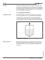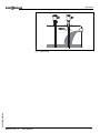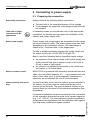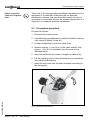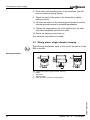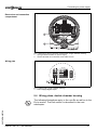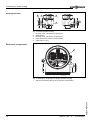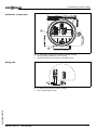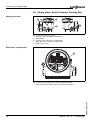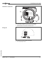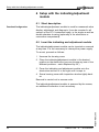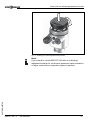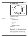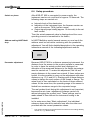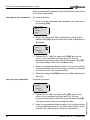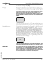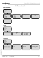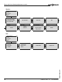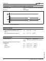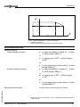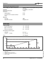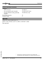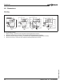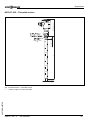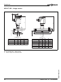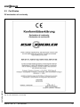
1
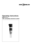
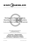
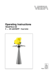
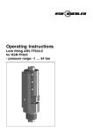
Operating Instructions
KSR-GT 655
4 … 20 mA/HART
WE'VE GOT
O
ABILITY
Contents
Contents
1
About this document
1.1
1.2
1.3
2
.
.
.
.
.
.
.
.
.
.
.
.
.
.
.
.
.
.
.
.
.
.
.
.
.
.
.
.
.
.
.
.
.
.
.
.
.
.
.
.
.
.
..
..
..
..
..
..
5
5
5
5
5
6
Configuration. . . . . . .
Principle of operation .
Adjustment . . . . . . . .
Storage and transport
.
.
.
.
.
.
.
.
.
.
.
.
.
.
.
.
.
.
.
.
.
.
.
.
.
.
.
.
.
.
.
.
.
.
.
.
.
.
.
.
.
.
.
.
.
.
.
.
.
.
.
.
.
.
.
.
.
.
.
.
.
.
.
.
.
.
.
.
..
..
..
..
7
7
8
8
General instructions. . . . . . . . . . . . . . . . . . . . . 9
Mounting information . . . . . . . . . . . . . . . . . . . . 10
Preparing the connection . . . . . . . . . . . . . .
Connection procedure . . . . . . . . . . . . . . . .
Wiring plans, single chamber housing . . . . .
Wiring plans, double chamber housing . . . .
Wiring plans, double chamber housing Exd .
.
.
.
.
.
..
..
..
..
..
12
13
14
15
18
Short description . . . . . . . . . . . . . . . . . . . .
Insert the indicating and adjustment module
Adjustment system . . . . . . . . . . . . . . . . . .
Setup procedure . . . . . . . . . . . . . . . . . . . .
Menu schematic . . . . . . . . . . . . . . . . . . . .
.
.
.
.
.
..
..
..
..
..
20
20
22
23
26
Maintenance and fault rectification
Maintenance . . . . . . . . . . . . . . . . . . . . . . . . . . 29
Fault rectification . . . . . . . . . . . . . . . . . . . . . . . 29
Instrument repair . . . . . . . . . . . . . . . . . . . . . . . 30
KSR-GT 655 - 4 … 20 mA/HART
30570-EN-050728
7.1
7.2
7.3
2
.
.
.
.
.
.
Setup with the indicating/adjustment module
6.1
6.2
6.3
6.4
6.5
7
.
.
.
.
.
.
Connecting to power supply
5.1
5.2
5.3
5.4
5.5
6
.
.
.
.
.
.
Mounting
4.1
4.2
5
Authorised personnel . . . . . . . .
Appropriate use. . . . . . . . . . . .
Warning about misuse . . . . . . .
General safety instructions . . . .
CE conformity . . . . . . . . . . . . .
Safety information for Ex areas.
Product description
3.1
3.2
3.3
3.4
4
4
4
4
For your safety
2.1
2.2
2.3
2.4
2.5
2.6
3
Function . . . . . . . . . . . . . . . . . . . . . . . . . . . . .
Target group . . . . . . . . . . . . . . . . . . . . . . . . . .
Symbolism used . . . . . . . . . . . . . . . . . . . . . . .
Contents
8
Dismounting
8.1
8.2
9
Dismounting procedure . . . . . . . . . . . . . . . . . . 31
Disposal . . . . . . . . . . . . . . . . . . . . . . . . . . . . . 31
Supplement
Technical data. . . . . . . . . . . . . . . . . . . . . . . . . 32
Dimensions . . . . . . . . . . . . . . . . . . . . . . . . . . . 38
Certificates . . . . . . . . . . . . . . . . . . . . . . . . . . . 41
30570-EN-050728
9.1
9.2
9.3
KSR-GT 655 - 4 … 20 mA/HART
3
About this document
1 About this document
1.1 Function
This operating instructions manual has all the information you
need for quick setup and safe operation of KSR-GT 655.
Please read this manual before you start setup.
1.2 Target group
This operating instructions manual is directed to trained
personnel. The contents of this manual should be made
available to these personnel and put into practice by them.
1.3 Symbolism used
Information, tip, note
This symbol indicates helpful additional information.
Caution, warning, danger
This symbol informs you of a dangerous situation that could
occur. Ignoring this cautionary note can impair the person and/
or the instrument.
Ex applications
This symbol indicates special instructions for Ex applications.
l
List
The dot set in front indicates a list with no implied sequence.
à
Action
This arrow indicates a single action.
1
Sequence
Numbers set in front indicate successive steps in a procedure.
30570-EN-050728
4
KSR-GT 655 - 4 … 20 mA/HART
For your safety
2 For your safety
2.1 Authorised personnel
All operations described in this operating instructions manual
must be carried out only by trained, specialised personnel
authorised by the operator. For safety and warranty reasons,
any internal work on the instruments must be carried out only
by personnel authorised by the manufacturer.
2.2 Appropriate use
KSR-GT 655 is a sensor for continuous level measurement.
2.3 Warning about misuse
Inappropriate or incorrect use of the instrument can give rise to
application-specific hazards, e.g. vessel overfill or damage to
system components through incorrect mounting or adjustment.
2.4 General safety instructions
KSR-GT 655 is a high-tech instrument requiring the strict
observance of standard regulations and guidelines. The user
must take note of the safety instructions in this operating
instructions manual, the country-specific installation standards
(e.g. the VDE regulations in Germany) as well as all prevailing
safety regulations and accident prevention rules.
2.5 CE conformity
KSR-GT 655 is in CE conformity with EMC (89/336/EWG),
fulfils the NAMUR recommendation NE 21 and is in CE
conformity with NSR (73/23/EWG).
Conformity has been judged acc. to the following standards:
EMC:
- Emission EN 61326: 2004 (class B)
- Susceptibility EN 61326: 2004 incl. supplement A
l
NSR: EN 61010-1: 2001
30570-EN-050728
l
KSR-GT 655 - 4 … 20 mA/HART
5
For your safety
2.6 Safety information for Ex areas
Please note the Ex-specific safety information for installation
and operation in Ex areas. These safety instructions are part of
the operating instructions manual and come with the Exapproved instruments.
30570-EN-050728
6
KSR-GT 655 - 4 … 20 mA/HART
Product description
3 Product description
3.1 Configuration
Scope of delivery
The scope of delivery encompasses:
l
l
Components
KSR-GT 655 level sensor
Documentation
- this operating instructions manual
- Ex-specific safety instructions (with Ex versions) and, if
necessary, further certificates
KSR-GT 655 consists of:
l
l
l
Process fitting with probe
Housing with electronics
Housing cover, optionally available with indicating/adjustment module
1
2
3
Fig.
1
2
3
1: KSR-GT 655 with plastic housing
Housing cover, optionally available with indicating/adjustment module
Housing with electronics
Process fitting
3.2 Principle of operation
30570-EN-050728
Area of application
KSR-GT 655 is a level sensor with pipe probe for continuous
level measurement.
It is designed for industrial use in all areas of process
technology and is used in liquids.
KSR-GT 655 - 4 … 20 mA/HART
7
Product description
Physical principle
High frequency microwave pulses are guided along a steel
rope or a rod. When reaching the product surface, the
microwave pulses are reflected. The running time is evaluated
by the instrument and outputted as distance.
Power supply
Two-wire electronics 4 … 20 mA/HART for power supply and
measured value transmission on the same cable.
The power supply range can differ depending on the
instrument version. The exact range is stated in the "Technical
data" in the "Supplement".
3.3 Adjustment
KSR-GT 655 can be adjusted with three different adjustment
media:
l
l
with indicating/adjustment module
a HART handheld
The entered parameters are generally saved in KSR-GT 655,
optionally also in the indicating/adjustment module.
3.4 Storage and transport
Packaging
Your instrument was protected by packaging during transport.
Its capacity to handle normal loads during transport is assured
by a test acc. to DIN EN 24180.
The packaging of standard instruments consists of environment-friendly, recyclable cardboard. For special versions, PE
foam or PE foil is also used. Dispose of the packaging material
via specialised recycling companies.
Storage and transport temperature
l
l
Storage and transport temperature see "Supplement –
Technical data – Ambient conditions"
Relative humidity 20 … 85 %
30570-EN-050728
8
KSR-GT 655 - 4 … 20 mA/HART
Mounting
4 Mounting
4.1 General instructions
Installation position
Select an installation position you can easily reach for
mounting and connecting as well as later retrofitting of an
indicating and adjustment module. The housing can be rotated
by 330° without the use of any tools. You can also install the
indicating and adjustment module in four different positions
(each displaced by 90°).
Handling
With screwed versions, the housing must not be used for
screwing in! Tightening can cause damages on the locking
piston of the housing.
To screw in, use the hexagon above the thread.
Moisture
Use the recommended cable (see chapter "Connecting to
power supply") and tighten the cable entry.
You can give your KSR-GT 655 additional protection against
moisture penetration by leading the connection cable downward in front of the cable entry. Rain and condensation water
can thus drain off. This applies mainly to mounting outdoors, in
areas where moisture is expected (e.g. by cleaning processes)
or on cooled or heated vessels.
Fig. 2: Measures against moisture penetration
30570-EN-050728
Measuring range
The reference plane for the measuring range of the sensors is
the seal surface of the thread.
Keep in mind that a min. distance must be maintained below
the reference plane and possibly also at the end of the probe measurement in these areas is not possible. These min.
distances are listed in the Technical data in the Supplement.
KSR-GT 655 - 4 … 20 mA/HART
9
Mounting
Pressure
The process fitting must be sealed if there is gauge or low
pressure in the vessel. Before use, check if the seal material is
resistant against the measured product. The max. permissible
pressure is stated in the "Technical data" in the "Supplement"
or on the type label of the sensor.
4.2 Mounting information
Installation position
Mount KSR-GT 655 in such a way that the probe does not
touch any installations or the vessel wall during installation.
In vessels with conical bottom it can be advantageous to
mount the sensor in the center of the vessel, as measurement
is then possible down to the lowest point of the vessel bottom.
Fig. 3: Vessel with conical bottom
Inflowing material
Make sure that the probe is not subjected to strong lateral
forces. Mount KSR-GT 655 at a location in the vessel where no
disturbing influence from e.g. filling openings, agitators, etc.
can occur.
30570-EN-050728
10
KSR-GT 655 - 4 … 20 mA/HART
Mounting
30570-EN-050728
Fig. 4: Lateral load
KSR-GT 655 - 4 … 20 mA/HART
11
Connecting to power supply
5 Connecting to power supply
5.1 Preparing the connection
Note safety instructions
Always observe the following safety instructions:
l
l
Connect only in the complete absence of line voltage
If overvoltages are expected, overvoltage arresters should
be installed.
Take note of safety
instructions for Ex
applications
In hazardous areas you should take note of the appropriate
regulations, conformity and type approval certificates of the
sensors and power supply units.
Select power supply
Power supply and current signal are transmitted via the same
two-wire connection cable. The power supply range can differ
depending on the instrument version. The exact range is
stated in the "Technical data" in the Supplement.
Provide a reliable separation between the supply circuit and
the mains circuits acc. to DIN VDE 0106 part 101.
Bear in mind the following factors regarding supply voltage:
l
l
the reduction of the output voltage of the power supply unit
under nominal load (with a sensor current of 20.5 mA or
22 mA in case of fault signal)
the influence of additional instruments in the circuit (see
load values in Technical data).
Select connection cable
KSR-GT 655 is connected with standard, unscreened two-wire
cable. An outer cable diameter of 5 ... 9 mm ensures the seal
effect of the cable entry. If electromagnetic interference is
expected, we recommend the use of screened cable.
Cable screening and grounding
Connect the cable screen on both ends to ground potential. In
the sensor, the screen must be connected directly to the
internal ground terminal. The ground terminal outside on the
housing must be connected to the potential equalisation (low
impedance).
12
KSR-GT 655 - 4 … 20 mA/HART
30570-EN-050728
If potential equalisation currents are expected, the connection
on the evaluation side must be made via a ceramic capacitor
(e.g. 1 nF, 1500 V). The low frequency potential equalisation
currents are thus suppressed, but the protective effect against
high frequency interference signals remains.
Connecting to power supply
Select connection
cable for Ex applications
Take note of the corresponding installation regulations for Ex
applications. In particular, make sure that no potential
equalisation currents flow over the cable screen. In case of
grounding on both sides this can be achieved by the use of a
capacitor or a separate potential equalisation.
5.2 Connection procedure
30570-EN-050728
Proceed as follows:
1
Unscrew the housing cover
2
If an indicating and adjustment module is installed, remove
it by turning it slightly to the left.
3
Loosen compression nut of the cable entry
4
Remove approx. 10 cm (4 in) of the cable mantle, strip
approx. 1 cm (0.4 in) insulation from the ends of the
individual wires
5
Insert the cable into the sensor through the cable entry
6
Lift the opening levers of the terminals with a screwdriver
(see following illustration)
7
Insert the wire ends into the open terminals according to
the wiring plan
Fig. 5: Connection steps 6 and 7
KSR-GT 655 - 4 … 20 mA/HART
13
Connecting to power supply
8
Press down the opening levers of the terminals, you will
hear the terminal spring closing
9
Check the hold of the wires in the terminals by lightly
pulling on them
10 Connect the screen to the internal ground terminal and the
external ground terminal to potential equalisation
11 Tighten the compression nut of the cable entry, the seal
ring must completely encircle the cable
12 Screw the housing cover back on
The electrical connection is finished.
5.3 Wiring plans, single chamber housing
The following illustrations apply to the non-Ex as well as to the
EEx ia version.
Housing overview
4
4
1
Fig.
1
2
3
4
4
2
3
6: Material versions, single chamber housing
Plastic
Aluminium
Stainless steel
Filter element for pressure compensation
30570-EN-050728
14
KSR-GT 655 - 4 … 20 mA/HART
Connecting to power supply
Electronics and connection
compartment
Display
I2C
1
1
2
5 6 7 8
2
Fig. 7: Electronics and connection compartment, single chamber housing
1 Spring-loaded terminals for power supply
2 Ground terminal for connection of the cable screen
Wiring plan
Display
I2C
1
2
5
6
7
8
1
Fig. 8: Wiring plan, single chamber housing
1 Power supply/Signal output
5.4 Wiring plans, double chamber housing
30570-EN-050728
The following illustrations apply to the non-Ex as well as to the
Ex ia version. The Exd version is described in the next
subchapter.
KSR-GT 655 - 4 … 20 mA/HART
15
Connecting to power supply
Housing overview
1
2
3
5
4
Fig.
1
2
3
4
5
9: Double chamber housing
Housing cover, connection compartment
Blind stopper
Housing cover, electronics compartment
Filter element for pressure compensation
Cable entry or plug
Electronics compartment
1
Display
I2C
1
2
5 6 7 8
Fig. 10: Electronics compartment, double chamber housing
1 Internal connection cable to the connection compartment
30570-EN-050728
16
KSR-GT 655 - 4 … 20 mA/HART
Connecting to power supply
Display
Connection compartment
1
1
2
I2C
2
Fig. 11: Connection compartment, double chamber housing
1 Spring-loaded terminals for power supply
2 Ground terminal for connection of the cable screen
Wiring plan
I2C
1
2
1
30570-EN-050728
Fig. 12: Wiring plan, double chamber housing
1 Power supply/Signal output
KSR-GT 655 - 4 … 20 mA/HART
17
Connecting to power supply
5.5 Wiring plans, double chamber housing Exd
Housing overview
1
2
3
5
4
Fig.
1
2
3
4
5
13: Double chamber housing
Housing cover, connection compartment
Blind stopper
Housing cover, electronics compartment
Filter element for pressure compensation
Cable entry or plug
Electronics compartment
1
Display
I2C
1
2
5 6 7 8
Fig. 14: Electronics compartment, double chamber housing
1 Internal connection cable to the connection compartment
30570-EN-050728
18
KSR-GT 655 - 4 … 20 mA/HART
Connecting to power supply
Connection compartment
1
1 2
2
Fig. 15: Connection compartment, double chamber housing Exd
1 Spring-loaded terminals for power supply and cable screen
2 Ground terminal for connection of the cable screen
Wiring plan
1
2
1
30570-EN-050728
Fig. 16: Wiring plan, double chamber housing Exd
1 Power supply/Signal output
KSR-GT 655 - 4 … 20 mA/HART
19
Setup with the indicating/adjustment module
6 Setup with the indicating/adjustment
module
6.1 Short description
Function/Configuration
The indicating/adjustment module is used for measured value
display, adjustment and diagnosis. It can be mounted in all
sensors of the GT 6 instrument family, in the single as well as
double chamber housing (optionally in the electronics or
connection compartment).
6.2 Insert the indicating and adjustment module
The indicating/adjustment module can be inserted or removed
at any time. It is not necessary to interrupt the power supply.
To mount, proceed as follows:
1
Unscrew the housing cover
2
Place the indicating/adjustment module in the desired
position on the electronics (you can choose any one of four
different positions - each displaced by 90°)
3
Press the indicating and adjustment module onto the
electronics and turn it to the right until it snaps in.
4
Screw housing cover with inspection window tightly back
on
Removal is carried out in reverse order.
The indicating/adjustment module is powered by the sensor,
an additional connection is not necessary.
30570-EN-050728
20
KSR-GT 655 - 4 … 20 mA/HART
Setup with the indicating/adjustment module
Fig. 17: Installing the indicating/adjustment module
30570-EN-050728
Note:
If you intend to retrofit KSR-GT 655 with an indicating/
adjustment module for continuous measured value indication,
a higher cover with an inspection glass is required.
KSR-GT 655 - 4 … 20 mA/HART
21
Setup with the indicating/adjustment module
6.3 Adjustment system
2
1
1.1
3
Key functions
Adjustment system
18: Indicating and adjustment elements
LC display
Indication of the menu item number
Adjustment keys
l
[OK] key:
- move to the menu overview
- confirm selected menu
- edit parameter
- save value
l
[–>] key to select:
- menu change
- list entry
- editing position
l
[+] key:
- modify value of a parameter
l
[ESC] key:
- interrupt input
- jump to the next higher menu
The sensor is adjusted via the four keys of the indicating and
adjustment module. The LC display indicates the individual
menu items. The functions of the individual keys are shown in
the above illustration. Approx. 10 minutes after the last
pressing of a key, an automatic reset to measured value
indication is triggered. Any values not confirmed with [OK] will
not be saved.
KSR-GT 655 - 4 … 20 mA/HART
30570-EN-050728
22
Fig.
1
2
3
Setup with the indicating/adjustment module
6.4 Setup procedure
Switch on phase
After KSR-GT 655 is connected to power supply, the
instrument carries out a self-test for approx. 30 seconds. The
following steps are carried out:
l
l
l
Internal check of the electronics
Indication of the instrument type, the firmware version as
well as the sensor TAGs (sensor name)
Output signal jumps briefly (approx. 10 seconds) to the set
fault current
Then the actual measured value is displayed and the corresponding current is transmitted to the cable.1)
Address setting HART-Multidrop
In HART-Multidrop mode (several sensors on one input) the
address must be set before continuing with the parameter
adjustment. You will find a detailed description in the operating
instructions manual of the indicating/adjustment module.
HART mode
Standard
Address 0
Parameter adjustment
Because KSR-GT 655 is a distance measuring instrument, the
distance from the sensor to the product surface is measured.
In order to have the actual product level displayed, an
allocation of the measured distance to the height percentage
must be carried out. To make this adjustment, the full and
empty distances in the vessel are entered. If these values are
known, it is also possible to carry out the adjustment with other
distances, e.g. 10 % and 90 %. Starting point of these distance
values is always the seal surface of the thread or flange. The
actual level is then calculated on the basis of these entered
values. At the same time, the operating range of the sensor is
limited from maximum range to the requested range.
The real product level during this adjustment is not important,
because the min./max. adjustment is always carried out
without changing the product level. These settings can be
made ahead of time without the instrument having to be
installed.
30570-EN-050728
In the main menu item "Basic adjustment", the individual
submenu items should be selected one after the other and
provided with the correct parameter values.
1)
KSR-GT 655 - 4 … 20 mA/HART
The values correspond to the actual level as well as to the settings already
carried out, e.g. default setting.
23
Setup with the indicating/adjustment module
Start your parameter adjustment with the following menu items
of the basic adjustment:
Carrying out min. adjustment
Proceed as follows:
1
▶
2
Move from the measured value display to the main menu
by pushing [OK].
Basic adjustment
Display
Diagnostics
Service
Info
Select the menu item "Basic adjustment" with [–>] and
confirm with [OK]. Now the menu item "Min. adjustment" is
displayed.
Min. adjustment
0.00 %
=
10.000 m(d)
8.000 m(d)
Carry out max. adjustment
3
Prepare the % value for editing with [OK] and set the
cursor to the requested position with [–>]. Set the
requested percentage value with [+] and save with [OK].
The cursor jumps now to the distance value.
4
Enter the appropriate distance value in m (corresponding
to the percentage value) for the empty vessel (e.g. distance
from the sensor to the vessel bottom).
5
Save the settings with [OK] and move to "Max. adjustment"
with [–>].
Proceed as follows:
Max. adjustment
100.00 %
=
1.000 m(d)
2.000 m(d)
Prepare the % value for editing with [OK] and set the
cursor to the requested position with [–>]. Set the
requested percentage value with [+] and save with [OK].
The cursor jumps now to the distance value.
2
Enter the appropriate distance value in m (corresponding
to the percentage value) for the full vessel. Keep in mind
that the max. level must lie below the dead band.
KSR-GT 655 - 4 … 20 mA/HART
30570-EN-050728
24
1
Setup with the indicating/adjustment module
3
Damping
Save the settings with [OK].
To suppress fluctuation in the measured value display, e.g.
caused by a turbulent product surface, an integration time can
be set. This time can be between 0 and 999 seconds. Please
note that the reaction time of the entire measurement will be
longer and the sensor will react to quick changes of the
measured value with a corresponding delay. In general, a time
of a few seconds is sufficient to smooth the measured value
display.
Damping
0s
Enter the requested parameter via the appropriate keys, save
your settings and jump to the next menu item with the [–>] key.
Linearization curve
A linearization is necessary for all vessels in which the vessel
volume does not increase linearly with the level – e.g. in a
cylindrical or spherical tank -–and the indication or output of
the volume is requested. Corresponding linearization curves
are preprogrammed for these vessels. They represent the
correlation between the level percentage and vessel volume.
By activating the appropriate curve, the volume percentage of
the vessel is displayed correctly. If the volume should not be
displayed in percent but e.g. in l or kg, a scaling can be also
set in the menu item "Display".
Linearization curve
Linear
Enter the requested parameter via the appropriate keys, save
your settings and jump to the next menu item with the [–>] key.
In this menu item you can enter an unambiguous designation
for the sensor, e.g. the measurement loop name or the tank or
product designation. In digital systems and in the documentation of larger plants, a singular designation should be entered
for exact identification of individual measuring sites.
30570-EN-050728
Sensor-TAG
KSR-GT 655 - 4 … 20 mA/HART
25
Setup with the indicating/adjustment module
Sensor-TAG
Sensor
With this menu item, the Basic adjustment is finished and you
can now jump to the main menu with the [ESC] key.
Optional settings
Additional adjustment and diagnosis options such as e.g.
scaling, simulation or trend curve presentation are shown in
the following menu schematic. You will find a detailed
description of these menu items in the operating instructions
manual of the indicating and adjustment module.
30570-EN-050728
26
KSR-GT 655 - 4 … 20 mA/HART
Setup with the indicating/adjustment module
6.5 Menu schematic
Basic adjustment
▶
Basic adjustment
Display
Diagnostics
Service
Info
1
Min. adjustment
0.00 %
=
10.000 m(d)
8.000 m(d)
1.1
Sensor-TAG
1.5
Max. adjustment
100.00 %
=
1.000 m(d)
2.000 m(d)
1.2
Unit
2.2
Damping
1.3
0s
Linearization curve
1.4
Linear
Sensor
Display
▶
Basic adjustment
Display
Diagnostics
Service
Info
Displayed value scaled
2
2.1
Volume
hl
Scaling
2.3
0 % = 000.5 hl
100 % = 005.0 hl
Diagnostics
▶
Basic adjustment
Display
Diagnostics
Service
Info
Peak values
3.1
Sensor status
OK
3.2
Choose curve
Echo curve
3.3
Echo curve
3.4
Presentation of the echo
curve
30570-EN-050728
Distance-min.: 0.234 m(d)
Distance-max: 5.385 m(d)
3
KSR-GT 655 - 4 … 20 mA/HART
27
Setup with the indicating/adjustment module
Service
▶
Basic adjustment
Display
Diagnostics
Service
Info
4
Current output
Meas. range: 4-20mA
Failure mode: 20.5mA
Min. current: 4mA
4.1
Language
4.5
Simulation
4.2
Start simulation?
Deutsch
Reset
4.3
Units of measurement
Reset now?
HART mode
Standard
Address 0
4.6
Date of manufacture
04. March 2005
Software version
4.10.00
5.2
4.4
m(d)
Copy sensor data
4.7
Copy from sensor
Copy to sensor
PIN
4.8
Enable?
Info
▶
Basic adjustment
Display
Diagnostics
Service
Info
Sensor type
KSR GT 6x
Serial number
12345678
5
5.1
Date of last change using PC
5.3
04. March 2005
Sensor details
5.4
Display now?
30570-EN-050728
28
KSR-GT 655 - 4 … 20 mA/HART
Maintenance and fault rectification
7 Maintenance and fault rectification
7.1 Maintenance
When used as directed in normal operation, KSR-GT 655 is
completely maintenance-free.
7.2 Fault rectification
Checking the 4 … 20 mA signal
Connect a hand-held multimeter with a suitable measuring
range acc. to the wiring plan.
?
4 … 20 mA signal not stable
l supply voltage too low or load resistance too high
à check and adapt, if necessary
?
4 … 20 mA signal missing
l incorrect connection to power supply
à Check connection acc. to chapter "Connection proce-
dure" and correct, if necessary, acc. to chapter "Wiring
plans"
l no power supply
à check cables for line break, repair, if necessary
l supply voltage too low or load resistance too high
à check and adapt, if necessary
?
Current signal greater than 22 mA or less than 3.6 mA
l Electronics module defective
à exchange instrument or return it for repair
30570-EN-050728
In Ex applications, the regulations for the wiring of intrinsically
safe circuits must be observed.
Fault messages via the indicating/adjustment module
?
E013
l no measured value available
à sensor in boot phase
KSR-GT 655 - 4 … 20 mA/HART
29
Maintenance and fault rectification
à sensor does not find an echo, e.g. because of faulty
installation or incorrect parameter adjustment
à Wrong sensor length entered
?
E017
l adjustment span too small
à Carry out a fresh adjustment and increase the distance
between min. and max. adjustment
?
E036
l no operable sensor software
à carry out a software update or return instrument for
repair
?
E042/E043
l hardware error, electronics defective
à exchange instrument or return it for repair
7.3 Instrument repair
If it is necessary to repair KSR-GT 655 please proceed as
follows:
l
l
l
l
Clean the instrument and pack it damage-proof
Attach a description of the fault, the ambient conditions and
measured product to the instrument
If necessary, attach a safety sheet to the instrument
Send the instrument to the respective address of your
agency or to the headquarters in Germany. In Germany to
the headquarters.
30570-EN-050728
30
KSR-GT 655 - 4 … 20 mA/HART
Dismounting
8 Dismounting
8.1 Dismounting procedure
Warning:
Before dismounting, be aware of dangerous process conditions such as e.g. pressure in the vessel, high temperatures,
corrosive or toxic products etc.
Take note of chapters "Mounting" and "Connecting to power
supply" and carry out the listed steps in reverse order.
8.2 Disposal
KSR-GT 655 consists of materials which can be recycled by
specialised recycling companies. We have purposely designed the electronic modules to be easily separable. Mark the
instrument as scrap and dispose of it according to national
government regulations (e.g. in Germany acc. to electronic
scrap ordinance).
Materials: see "Technical data"
30570-EN-050728
If you cannot dispose of the instrument properly, please
contact us about disposal methods or return.
KSR-GT 655 - 4 … 20 mA/HART
31
Supplement
9 Supplement
9.1 Technical data
General data
Material 316L corresponds to 1.4404 or 1.4435
Materials, wetted parts
- Process fitting
316L and TFM PCTFE +25%GF; Hastelloy
C22 2.4602 and TFM PCTFE +25%GF
-
Seal
Viton, Kalrez 6375 and EPDM
-
tube ø 21.3 mm (ø 0.84 in)
316L / Hastelloy C22 2.4602
Materials, non-wetted parts
- Housing
plastic PBT (Polyester), Alu-die casting powder-coated, stainless steel 316L
-
Seal ring between housing and
housing cover
NBR (stainless steel housing), silicone (Alu/
plastic housing)
-
Inspection window in housing cover
(option)
Polycarbonate
-
Ground terminal
316L
Weights
- Plastic housing
760 g (27 oz)
-
Aluminium housing
1170 g (41 oz)
-
Aluminium double chamber housing
1470 g (52 oz)
-
Stainless steel housing
1530 g (54 oz)
-
Tube (ø21.3 mm/ø0.84 in)
approx. 1000 g/m (approx. 10.8 oz/ft)
Lengths (L)
- Tube (ø21.3 mm/ø0.84 in)
0.5 … 4 m (1.6 … 13 ft)
lateral load - tube ø 21.3 mm (ø 0.84 in)
60 Nm (530 lbf/in)
Output variable
Output signal
Resolution
Fault signal
32
NE 43
KSR-GT 655 - 4 … 20 mA/HART
30570-EN-050728
Current limitation
Load
Integration time (63 % of the input
variable)
Fulfilled NAMUR recommendation
4 … 20 mA/HART
1.6 µA
current output unchanged; 20.5 mA; 22 mA;
<3.6 mA (adjustable)
22 mA
see load diagram in Power supply
0 … 999 s, adjustable
Supplement
Input variable
Parameter
Min. dielectric figure
dead band with tube ø 21.3 mm (ø 0.84 in)
- top
level of liquids
Er >1.4
50 mm (2.0 in)
1
4
2
3
Fig.
1
2
3
4
19: Measuring ranges of KSR-GT 655
Reference plane
Probe length
Measuring range
Upper dead band
Accuracy (similar to DIN EN 60770-1)
Reference conditions acc. to DIN EN 61298-1
- Temperature
18 … +30°C (64 … +86°F)
Relative humidity
45 … 75 %
Atmospheric pressure
860 … 1060 mbar (86 … 106 kPa/
12.5 … 15.4 psi)
30570-EN-050728
-
KSR-GT 655 - 4 … 20 mA/HART
33
Supplement
Characteristic curve deviation and measurement characteristics
Temperature drift
Accuracy
0.06 %/10 K relating to the max. measuring
range
see diagram
10 mm
3 mm
6m
0,05 m
-3 mm
-10 mm
Fig. 20: Accuracy - coax version KSR-GT 655
Ambient conditions
Ambient, storage and transport temperature
- without indicating/adjustment module
-40 … +80°C (-40 … +176°F)
-
-20 … +70°C (-4 … +158°F)
with indicating/adjustment module
Process conditions
Process pressure
Process temperature (thread or flange
temperature)
- Viton
-1 … 40 bar (-100 … 4000 kPa or
-14.5 … 580 psi) dependent on the process
fitting
-40 … +150°C (-40° … +302°F)
-
EPDM
-40 … +150°C (-40° … +302°F)
-
Kalrez 6375
-20 … +150°C (-4° … +302°F)
30570-EN-050728
34
KSR-GT 655 - 4 … 20 mA/HART
Supplement
1
˚C
80
60
40
20
2
-40
0
50
100
150
˚C
Fig. 21: Ambient temperature – Product temperature
1 Ambient temperature
2 Product temperature (depending on the seal material)
Electromechanical data
Cable entry/plug2)
- Single chamber housing
l
or:
l
1x cable entry M20x1.5 (cable-ø 5 … 9 mm),
1x blind stopper M20x1.5
1x closing cap ½ NPT, 1x blind stopper
½ NPT
or:
-
Double chamber housing
l
1x plug (depending on the version), 1x blind
stopper M20x1.5
l
1x cable entry M20x1.5 (cable-ø 5 … 9 mm),
1x blind stopper M20x1.5
or:
l
1x closing cap ½ NPT, 1x blind stopper
½ NPT
or:
l
30570-EN-050728
Spring-loaded terminals
for wire cross sections up to 2.5 mm²
2)
KSR-GT 655 - 4 … 20 mA/HART
1x plug (depending on the version), 1x blind
stopper M20x1.5
Depending on the version M12x1, acc. to DIN 43650, Harting, AmphenolTuchel, 7/8" FF
35
Supplement
Indicating and adjustment module
Power supply and data transmission
through sensor via gold-plated sliding contacts
(I²C bus)
LC display in dot matrix
4 keys
Indication
Adjustment elements
Protection
- unassembled
-
IP 20
mounted into the sensor without
cover
IP 40
Materials
- Housing
ABS
-
Polyester foil
Inspection window
Power supply
Supply voltage
- non-Ex instrument
14 … 36 V DC
-
EEx ia instrument
14 … 30 V DC
-
EExd ia instrument
20 … 36 V DC
Permissible residual ripple
- <100 Hz
Uss<1 V
-
Uss <10 mV
100 Hz … 10 kHz
Load
see diagram
Ω
1000
750
3
500
2
1
250
4
14
36
18
20
22
24
26
28
30
32
34
36
V
22: Voltage diagram
HART load
Voltage limit EEx ia instrument
Voltage limit non-Ex/Exd instrument
Supply voltage
30570-EN-050728
Fig.
1
2
3
4
16
KSR-GT 655 - 4 … 20 mA/HART
Supplement
Electrical protective measures
Protection
- Plastic housing
IP 66/IP 67
-
Alu and stainless steel standard
IP 66/IP 68 (0.2 bar)3)
-
Alu and stainless housing, optionally
available
IP 66/IP 68 (1 bar)
Overvoltage category
Protection class
III
II
Approvals4)
ATEX II 1G, 1/2G, 2G EEx ia IIC T6
ATEX II 1/2G, 2G EEx d ia IIC T6, ATEX II 1/2D IP66 T, WHG
30570-EN-050728
Ship approvals
3)
4)
KSR-GT 655 - 4 … 20 mA/HART
Requirement to maintain the protection is the suitable cable.
Deviating data with Ex applications: see separate safety instructions.
37
Supplement
9.2 Dimensions
Housing
~ 87 (96)
~ 69
~ 69
ø 77
~ 116
ø 84
½
116 (*125)
20x1,5
½ NPT
½
1
Fig.
1
2
3
4
120 (*129)
112 (*123)
117 (*128)
M16x1,5
2
M20x1,5/
½ NPT
3
4
23: Housing versions
Plastic housing (* dimension with integrated indicating/adjustment module)
Stainless steel housing (* dimension with integrated indicating/adjustment module)
Aluminium double chamber housing (* dimension with integrated indicating/adjustment module)
Aluminium housing (* dimension with integrated indicating/adjustment module)
30570-EN-050728
38
KSR-GT 655 - 4 … 20 mA/HART
Supplement
158mm (6 7/32")
KSR-GT 655 – Threaded version
½ NPT
L
G1½
27mm (1 1/16")
NPT
ø 21,3mm
(27/32")
30570-EN-050728
Fig. 24: KSR-GT 655 – Threaded version
L = Sensor length, see Technical data
KSR-GT 655 - 4 … 20 mA/HART
39
Supplement
KSR-GT 655 – flange version
~ 69
179
158
ø 77
d
b
b
d
k
D
L
L
k
D
≥ DN 40 / 1½"
DN 25 PN 40
DN 40 PN 40
1" 150 lb
1" 300 lb
D
ø115
ø150
ø108
ø124
b
k
18
ø85
18
ø110
14,2 ø78,2
17,5 ø88,9
≥ DN 50 / 2"
d
4xø14
4xø18
4xø15,7
4xø19,1
DN 50 PN 40
DN 80 PN 40
DN 100 PN 16
2" 150 lb
2" 300 lb
3" 150 lb
3" 150 lb
D
ø165
ø200
ø220
ø152,4
ø165,1
ø190,5
ø209,5
b
k
d
20
ø125
4xø18
24
ø160
8xø18
20
ø180
8xø18
19,1 ø120,7 4xø19,1
22,4 ø127 4xø19,1
23,9 ø152,4 4xø19,1
28,4 ø168,1 4xø22,4
Fig. 25: KSR-GT 655 – flange version
L Sensor length, see Technical data
30570-EN-050728
40
KSR-GT 655 - 4 … 20 mA/HART
9.3 Certificates
30570-EN-050728
CE declaration of conformity
Fig. 26: CE declaration of conformity
KSR-GT 655 - 4 … 20 mA/HART
41
30570-EN-050728
42
KSR-GT 655 - 4 … 20 mA/HART
30570-EN-050728
KSR-GT 655 - 4 … 20 mA/HART
43
KSR KUEBLER Nivau >Messtechnik AG
Im Kohlstatterfeld 17
69439 Zwingenberg
Germany
Phone +49 6263 87-0
Fax +49 6263 8799
E-mail: [email protected]
www.ksr-kuebler.com
All statements concerning scope of delivery, application,
practical use and operating conditions of the sensors and
processing systems correspond to the information available at the time of printing.
Technical data subject to alterations
30570-EN-050728