1
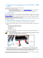
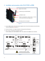
Please keep careful!
Installation and maintenance
Operating Instructions
TAC4 DG + TCP/IP / GPRS
Status: 06/2013
Paul Wärmerückgewinnung GmbH
August-Horch-Straße 7
08141 Reinsdorf
Germany
Tel.: +49(0)375 - 303505 - 0
Fax: +49(0)375 - 303505 - 55
Table of contents
0
Preamble ................................................................................................................................. 2
1
Introduction ............................................................................................................................ 2
1.1
Safety ....................................................................................................................................... 2
1.2
Used symbols........................................................................................................................... 2
2
Functionalities of the regulation .......................................................................................... 3
3
Operating principle ................................................................................................................ 4
4
Which module to choose – TCP/IP or GPRS?..................................................................... 4
5
Configuration and programming of the TAC4 TCP/IP or GPRS module .......................... 5
5.1
Configuration file ...................................................................................................................... 5
5.2
Programming of the TAC4 TCP/IP or GPRS module from the SD card .................................. 5
6
Installation and connection of the TAC4 TCP/IP or GPRS ................................................ 6
7
PC Configuration to view web pages ................................................................................... 7
7.1
Compatible Web browser......................................................................................................... 7
7.2
Installation of the “WebFormViewSetup.exe” viewer ............................................................... 7
8
Use of web pages ................................................................................................................... 7
8.1
Home........................................................................................................................................ 7
8.2
8.2.1
8.2.2
8.2.3
8.2.4
8.2.5
8.2.6
Visualization ............................................................................................................................. 8
Synoptic ................................................................................................................................... 8
Alarms ...................................................................................................................................... 8
Setup ........................................................................................................................................ 8
m³/h+T° .................................................................................................................................... 8
I/O status .................................................................................................................................. 9
Configuration ............................................................................................................................ 9
8.3
Control...................................................................................................................................... 9
8.4
Setup ........................................................................................................................................ 9
8.5
Time table .............................................................................................................................. 10
8.6
8.6.1
8.6.2
8.6.3
8.6.4
TAC4 Network ........................................................................................................................ 11
Configuration .......................................................................................................................... 11
Overview ................................................................................................................................ 11
Alarm warning ........................................................................................................................ 12
Logging .................................................................................................................................. 12
1
0 Preamble
PLEASE READ THIS MANUAL CAREFULLY BEFORE INASTALLATION AND COMMISSONING!
THIS MANUAL HAS BEEN MADE WITH GREATEST CARE.
HOWEVER, NO RIGHTS CAN BE DERIVED THEREFROM. WE RESERVE THE RIGHT AT ANY TIME
TO PARTIALLY OR ENTIRELY CHANGE THE CONTENT OF THIS MANUAL WITHOUT PRIOR
NOTICE.
This manual contains all the best for an assembly plant and a heat recovery unit (HRU) necessary
information. The manual also serves as a handbook for installation, maintenance and customer service
work. We recommend that any intervention in the appliance installation company should be consulted.
Subject of this operating manual is the control unit TAC4 and the modules TCP/IP and GPRS. Possible
accessories are only described insofar as it is necessary for the appropriate operation. Please see the
particular manuals for further information on accessories.
If you have any questions that have not been answered or have not been sufficiently answered in this
documentation, please contact the company Paul Wärmerückgewinnung GmbH. We will be glad to help
you.
1 Introduction
1.1
Safety
Please always observe the safety instructions in this operating manual. The non-observance of the safety
instructions, warning notices, notes and instructions can lead to injuries or damages to the maxi.
• Unless otherwise stated in this operating manual, only an authorised installer is entitled to install,
connect, put into operation and maintain the maxi;
• The installation of the maxi is to be performed according to the general local building, safety and
installation instructions of the corresponding local authorities, of the water works and electric
works and other official regulations and directives;
• Always follow the safety instructions, warning notices, notes and instructions described in this
operating manual;
• Please keep this manual during the complete life time of the maxi in proximity to the device;
• The instructions for the regular replacement of the filters or the cleaning of the supply and exhaust
air valves are to be strictly followed;
• The specifications stated in this document may not be changed;
• Any modification of the maxi is prohibited;
• In order to guarantee that the device will be regularly controlled, it is recommended to conclude a
maintenance contract. Your supplier can give you the addresses of authorised installers in your
area.
1.2
Used symbols
The following symbols are used in this manual:
Caution, special note!
Risk of:
2
- injury of the user or the installer
- damages to the device
- impairment of the operation of the device if the instructions are not
carried out properly
2 Functionalities of the regulation
The TAC4 DG controller is mounted in the units of maxi-series.
The functionalities of this TAC4 DG control board are described in detail in the “Operating
instructions TAC4+RC” manual.
The TAC4 DG control board provides the following functionalities:
•
•
•
•
•
•
•
•
•
Control of supply and exhaust fans in constant air flow (CA), constant pressure (CPs) and
constant airflow linked to a 0-10V signal (LS) mode.
Management of 6 time slots.
Default, set point and pressure alarms.
Management of airflows in case of fire alarm.
BOOST function that helps to force the supply and exhaust airflows to a value set beforehandoverriding all configurations and conditions.
Automatic management of the 100% bypass for free cooling.
Automatic management of the opening and closing of valves mounted on the suction side.
Anti-frost protection of the heat recovery exchanger by modulation of the supply airflow or by
regulating the power of the pre-heating electric coil (KWin).
Regulation of the post-heating water (NV) or electric (KWout) coils to maintain a constant supply
temperature.
The following options can be combined with the TAC4 DG control board:
•
Option SAT TAC4 BA/KW:
Regulation of 2 external heat exchangers (hot and/or cold).
•
Option RC TAC4:
Local remote control that can be used for the configuration, display and control of the TAC4 unit
to which it is connected.
•
Option SAT3:
Circuit with 2 relays for
- “Fans ON” and “Pressure alarm” signals (if in position O.R.1 / O.R.2)
or
"Circulator control” and “Bypass status signal” (if in position O.R.3 / O.R.4)
3
3 Operating principle
The TAC4 TCP/IP and GPRS modules are automated units with a built-in web server. Once programmed,
the module contains software composed of web pages used for the configuration, control and display of
TAC4 units connected to this module.
Basic diagram:
1
1
2
2
= MODBUS RTU communication
= Access to the TAC4 MODULE web pages.
There are different possibilities:
- Internet connection via Ethernet (TCP/IP)
- Internet connection via GPRS
- Intranet (local) connection via Ethernet (TCP/IP)
4 Which module to choose – TCP/IP or GPRS?
The TAC4 TCP/IP module can be used to:
- Access the TAC4 module web pages via the Ethernet connection
- Send alarm messages by e-mail
The TAC4 GPRS module can be used to:
- Access the TAC4 Module web pages via the Ethernet connection
- Access the TAC4 Module web pages via GPRS *
- Send alarm messages by e-mail via Ethernet
- Send alarm messages by e-mail via GPRS *
- Send alarm messages by e-mail via SMS *
* These functionalities require a SIM card (not supplied).
4
5 Configuration and programming of the TAC4 TCP/IP or GPRS
module
The TAC4 TCP/IP or GPRS is delivered non-programmed.
Programming is carried out in two steps:
- Entry of configuration settings: via the website http://TAC4.atmdata.be (you will need an SD
card, maximum 2GB (not supplied)).
- Programming of the module using an SD card: follow the procedure in paragraph 5.2.
5.1
Configuration file
The configuration settings such as the IP address, the access data, the use of a SIM card (or not) or the
data of an SMTP server to send e-mail for instance, must be entered on the website:
http://TAC4.atmdata.be.
A configuration file “plug&go.bin” containing all the settings of your TAC4 TCP/IP or GPRS module will be
generated from this site. Save this file on an SD card.
Use an SD card with a maximum capacity of 2GB (SDHC cards with a capacity of 4GB or more are not
recognized by the module).
5.2
Programming of the TAC4 TCP/IP or GPRS module from the SD card
1) Remove the TAC4 TCP/IP or GPRS module from its support using the mounting screws.
2) The programming must be carried out on a “bare” TAC4 TCP/IP or GPRS module. So make sure you
unplug:
- The 24VDC power supply terminal block
- The RS 485 communication terminal block
- The Ethernet cable
- The antenna
- The SIM card (if present)
3) Insert the SD card containing the configuration file in (2) (figure 1), press it as far as possible, so that
it does not exceed the Module.
The SD card is difficult to remove. You will need a pair of long-nosed pliers or to stick
a sticker to get a hold of the SD card (see Figure 1).
(1)
(2)
SD card
SIM card
SIM card support
Figure 1
4) Plug the 24VDC power supply terminal block to the Module (see Figure 3). The module will detect
automatically the presence of a new “Plug&go.bin” file and launch the loading of the programme.
The PGM LED stops blinking (ON or OFF) during the loading of the programme (about 1 minute).
When the programming is finished, the LED starts blinking again (2 blinks per second).
Once the module has been programmed, the SD card is no longer necessary. Shut down the 24VDC
power supply and remove it from the TAC4 TCP/IP and GPRS module.
5
6 Installation and connection of the TAC4 TCP/IP or GPRS
Support of the module
Antenna (only for GPRS module)
ETHERNET cable
RS485 communication terminal block to TAC4
circuits and 24VDC power supply block
Mounting screw on the support
Figure 2
1) For the GPRS module, mount the antenna supplied with the TAC4 GPRS module and install the SIM
card (not supplied) (see (1) Figure 1).
2) Fasten the module on its support using the mounting screws (see Figure 2).
3) Carry out the connections as indicated in Figure 3
For the assembly of the SAT MODBUS circuit: see “MI SAT TAC4 MODBUS” documentation
TAC 4
F4
F3
F2
F1
IN
OUT
L N
OUT
F2
F4
F1
F3
OUT
IN
IN
OUT
MOTOR CONTROL CABLES
CT
4 3 2 1
IN
BYPASS
MOTOR CONTROL CABLES
CT
ASS
RELAY
RELAY
RESET
CT
ON
RESET
CT
BYPASS
ON
Alarm
O.R.4
SAT MODBUS
ETHERNET
Cable
(RJ45 connector)
T/R
AF
SAT BA/KW
O.R.1
O.R.2
O.R.3
O.R.4
SAT MODBUS
SAT MODBUS (2)
SAT MODBUS (1)
Rx Tx
Rx Tx
SAT BA/KW
LK
ETHERNET
O.R.3
On
Alarm
AF
R.2
GSM-GPRS
RELAY
LT-100-GE
100
PGM
Stop
Run-Re set
A+ B- GND A+ B- GND
Rx Tx
PS/485/232
A+ B- GND A+ B- GND
RELAY
AL1
A+
Vin
B-
Bat
Rx
Out
Tx
G nd
8
9
AL1
CNT
DIG IN-OUT
6
7
4
5
2
3
0
1
Gnd
V+
A and B connections crossed
www.tbox.biz
Figure 3
6
24Vdc
SUPPLY
+
-
7 PC Configuration to view web pages
7.1
Compatible Web browser
“Internet explorer” must be used to view Web pages.
Other browsers are not compatible!
7.2
Installation of the “WebFormViewSetup.exe” viewer
To view the pages, you must install the “WebFormViewSetup.exe” viewer on your PC.
This application can be downloaded from: http://TAC4.atmdata.be.
8 Use of web pages
Enter the IP address of your TAC4 TCP/IP or GPRS module in the Internet explorer address bar.
For example: http://192.168.0.1
You will then access the web pages of the TAC4 module corresponding to this address.
Presentation of the functionalities on each screen:
8.1
Home
The “Home” page is used to:
- Identify the TAC4 module to which you are connected
-
Choose the address of the TAC4 unit with which you are going to communicate
-
View all the TAC4 units connected to the TAC4 module (address of the unit on the network, type
of unit and name given to the unit: these elements are configured in the “TAC4 Network” screen).
7
8.2
Visualization
The pages of this menu are used to view all the settings of the TAC4 unit with which you communicate
(the address and the name of the unit are indicated at the top of the page).
This menu comprises different sub-categories presented in the form of tabs.
8.2.1
Synoptic
The “Synoptic” tab displays a basic diagram of the unit containing the most useful information of the
ventilation unit. This screen is automatically depending on the state of the unit and the options present.
It indicates:
- The inlet and outlet temperatures of each flow;
- The supply and extract flows;
- The opening and closing of the bypass, the antifrost and the valves (option) (red/dark green =
OFF; light green = ON);
- The different components mounted on the unit and their current operation (options: KWin,
KWout, hot water battery NV);
- An “SAT BA” button that displays the current operating characteristics of the external coils
(options: BA+, BA-, KW);
- Two alarm diodes that indicate the current state of the alarm (red = default, green = OK). Click on
one of these diodes to access the “Alarms” tab directly.
8.2.2
Alarms
The “Alarms” tab is used to display the state of the different alarms.
8.2.3
Setup
The “Setup” tab is used to view the different set points (CA/LS/CPs/OFF mode, supply flow and
temperature requested as well as pressure alarms) configured in the SETUP currently in operation.
8.2.4
m³/h+T°
The “m³/h+T°” tab is used to view:
- The airflows and pressures for supply and exhaust
8
8.2.5
All the temperatures measured by the sensors of the unit
The operating time of the unit.
I/O status
The “I/O status” tab shows summary of the status of all inputs and outputs on the TAC4 control board.
8.2.6
Configuration
The “Configuration” tab shows the factory configuration, i.e. the type of unit as well as the different
options included in it. It also shows the software version of the TAC4 circuit.
8.3
Control
The “Control” menu is used to control the unit of the selected address. This page depends on the
operating mode chosen.
Functionalities available:
- Display of the airflow control mode
- Possibility to select the ventilation control mode:
• RC position; control via the RC connected.
• Auto position: control according to time slots.
8.4
-
• Manual position: control via the
buttons of this screen.
Display of alarms using the red or green diodes
-
Choice and display of the ventilation level (LED under the
buttons)
Display of the current real airflows to the right of the screen;
Direct control via the “Boost”, “Bypass”, “Heating” and “Cooling” buttons.
Setup
The “Setup” menu is used to configure the setting of the fan’s operating mode, the supply temperatures
and the pressure alarm.
This page varies depending on the operating mode chosen.
9
8.5
Time table
The ‘Time table” menu is used to program the operating mode and the setting points for the fans, the
supply temperature and the position of the bypass on a weekly basis.
Click on the box containing the time slot to open the configuration window of the corresponding time slot.
Seasonal management of the bypass and the cold and hot coils is provided under the Seasonal manager
tab.
10
8.6
TAC4 Network
The “TAC4 Network” menu is used to configure and supervise all the units present in the network.
8.6.1
Configuration
The “Configuration” tab is used to add/remove and to address units on the network.
Each TAC4 unit is factory programmed with the address Modbus 1. To network several units, the
different units must be re-addressed.
There are several methods possible for re-addressing the units:
1) By connecting directly on each unit using a TAC4 RC:
Change address via SETUP ADVANCE
2) Via the web pages of the TAC4 TCP/IP or GPRS module by supplying one unit at a time:
Connect all the TAC4 units in a network but supply only one unit at a time. You will then only
have one unit with the address 1 on the network. You can then change its address via the web
pages, then supply the next unit to change its address and so forth.
3) Via the web pages of the TAC4 TCP/IP or GPRS module by adding a unit to the TAC4 network
each time:
Connect a unit to the network physically and change the address. Then add a unit at a time to
the network and change the address.
Once all the units are present, scan the network. The TAC4 TCP/IP or GPRS module
will list all the units present on the network. You can then enter a unit name.
8.6.2
Overview
The “Overview” tab is used to get an overview of your network of TAC4 units. It shows the main
information for each unit.
The units connected in the “configuration” tab are not automatically inserted in the supervision table. To
add a unit in this table, click in the address box and enter the address corresponding to the unit you want
to view.
The maximum number of units under supervision is 10.
Attention: Only the units entered under this tab will be able to send an alarm (“Alarm warning” tab) via email and/or SMS.
11
8.6.3
Alarm warning
The “Alarm warning” tab is used to select the type of alarms to be sent and to configure the dispatch by
SMS and/or by e-mail.
To select the types of alarm for which you want to send a message, tick the boxes of the desired alarms.
Remember only the units present in the “Overview” tab will be concerned by the
alarm messages sent.
Send alarm by SMS:
Equipment needed:
• TAC4 GPRS module with SIM card.
Operation:
3 telephone numbers can be configured. During an alarm, the messages are sent simultaneously to the 3
numbers.
You can test how the dispatch functions by clicking on the “Test SMS” button.
Send alarm by e-mail:
Equipment needed:
• TAC4 TCP/IP module with configured SMTP server
• TAC4 GPRS module with SIM card and configured SMTP server (by Ethernet or GPRS)
Operation:
3 e-mail addresses can be configured. During an alarm, the messages are sent simultaneously to the 3
addresses.
You can test the operation of the dispatch by clicking on the “Test EMAIL” button.
8.6.4
Logging
This tab is used to obtain certain indications on the state of connection of the TAC4 TCP/IP or GPRS
module on the dispatching of the alarm messages.
As of June 4th 2013
_____________________________________________________________________________________________
Although we put a lot of care in the making of our documentation, we cannot be held responsible for any error and/or
omissions that could have slipped in.
12