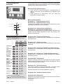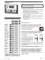
1
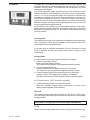
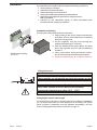
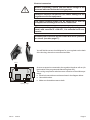
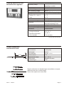
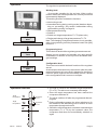
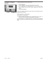
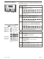
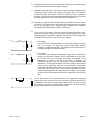
WELBA
Milk-cooling regulator
MRF-M
100994 - © by WELBA - 28/08/08
Installation and operating instructions
for plant engineering companies
WELBA GmbH
Electronic Control Engineering
Gewerbepark Siebenmorgen 6
D-53547 Breitscheid
Phone:
Fax:
E-mail:
Net:
+49 (0)2638 / 9320-0
+49 (0)2638 / 9320-20
[email protected]
www.welba.de
Content
Function . . . . . . . . . . . . . . . . . . . . . . . . . . . . . . . . . . . . . . . . . Page 3
Intended use . . . . . . . . . . . . . . . . . . . . . . . . . . . . . . . . . . . . . Page 4
Safety . . . . . . . . . . . . . . . . . . . . . . . . . . . . . . . . . . . . . . . . . . . Page 4
Installation . . . . . . . . . . . . . . . . . . . . . . . . . . . . . . . . . . . . . . . Page 5
Electrical connection . . . . . . . . . . . . . . . . . . . . . . . . . . . . . . . Page 6
Technical data regulator . . . . . . . . . . . . . . . . . . . . . . . . . . . . . Page 7
Sensor dimensions and technical data . . . . . . . . . . . . . . . . . Page 7
Operation . . . . . . . . . . . . . . . . . . . . . . . . . . . . . . . . . . . . . . . . Page 8
Operation overview . . . . . . . . . . . . . . . . . . . . . . . . . . . . . . . . Page 8
Parameter settings in general . . . . . . . . . . . . . . . . . . . . . . . . Page 9
Working level operation . . . . . . . . . . . . . . . . . . . . . . . . . . . . . Page 10
Programming level operation . . . . . . . . . . . . . . . . . . . . . . . . . Page 11
Configuration level operation . . . . . . . . . . . . . . . . . . . . . . . . . Page 12
Intermediate stirring options during cooling . . . . . . . . . . . . . . Page 14
Function permanent stirring . . . . . . . . . . . . . . . . . . . . . . . . . . Page 14
Setting the actual value correction . . . . . . . . . . . . . . . . . . . . . Page 15
Fault indication on the display . . . . . . . . . . . . . . . . . . . . . . . . Page 15
General measures when using electronic control systems . . Page 16
MRF-M
28/08/08
Page 2
Function
The MRF-M is a microprocessor-regulated milk-cooling regulator with
automatic afterstirring. It has separate relay contacts for the compressor
contactor and the stirrer. The measured milk temperature is shown
constantly on the display.
Two freely adjustable target temperatures may be selected by push
buttons. Should the milk temperature exceed the chosen target temperature (T1 or T2) by the hysteresis value, the compressor and stirrer are
automatically switched on. Once the target temperature is reached, the
compressor contactor switches off. The stirrer continues for the programmed period. During refrigeration pauses, the stirrer automatically
switches on again according to the programmed intervals, to ensure an
even temperature throughout the milk.
Independently of this, short or long "intermediate stirring" can be selected by pressing a button. Software can aIso be used to programme the
MRF-M for "permanent stirring", i.e. the agitator is switched on and off by
pressing a button.
Cooling mode:
Press the button cooling: the compressor and agitator operate automatically. In between cooling periods (agitator and compressor LEDs off),
intermediate stirring can be activated.
lf the start delay is activated (parameter c80 >0), the start of cooling
mode is delayed. Pressing the button twice causes cooling to start
immediately.
Stirring mode
lf cooling mode is active (temperature ist shown on display):
! “Short" intermediate stirring:
Briefly press the "Agitator” button.
"sho" appears in the display, and the agitator starts to operate.
! "Long" intermediate stirring:
Press and hold down the "Agitator” button for 5 seconds.
"Ion" appears in the display, and the agitator starts to operate.
! Continuous stirring (only if set at parameter level): Press the
"Agitator” button. "On" appears in the display. The agitator
operates continuously until the "Agitator" button is pressed again.
lf OFF mode is active (’OFF’ ist shown on display):
! Continuous stirring while cooling is switched off:
Press the "Agitator" button. Actual temperature is shown in the
display, and the agitator-LED is flashing.
Off mode
The regulator can be switched off using the "OFF" button. "OFF" appears in the display. Both the output relays for the agitator and compressor
are deactivated.
CAUTION: The regulator is live even when switched off.
T1 /T2
Switch between target temperatures (when cooling mode is active only).
MRF-M
28/08/08
Page 3
Intended use
These operating instructions contain important technical
and safety information.
Please read carefully before installation and before any
work on or with the regulator.
The microprocessor-controlled regulator type MRF-M is used to control
heating and cooling systerns, alarm devices, fans, etc. Any other use of
the device is permitted only with prior written permission from the
manufacturer.
The microprocessor regulator is ready for use once the parameters
have been set. lt should not be used beföre this has been done, as this
might result in damage to the plant and the item to be cooled or heated.
The device is fitted with a resistance temperature sensor. The output
ports are designed as potential-free relay ports.
The device must not be installed in potentially explosive
atmospheres.
The microprocessor-controlled regulator type MRF-M fulfils
the EC requirements for electromagnetic compatibility (EMC)
and the Low Voltage Directive (LVD).
The safety components meet the VDE regulations.
Safety
These operating instructions contain important technical
and safety information. Please read them carefully before
installation and before working on or with the regulator.
The microprocessor regulator must be installed by an
authorised specialist, observing local safety regulations.
Access to the environment when connected must be
restricted to specialised personnel.
The microprocessor regulator contains live components
and must not be opened up.
lt must not be used if the housing or connection terminals
are damaged.
No fluids must penetrate the housing.
The microprocessor regulator may not be exported to the
USA without the manufacturer's express permission.
MRF-M
28/08/08
Page 4
Installation
It is essential not to install the device under the following conditions:
! severe jolting or vibration
! permanent contact with water
! relative humidity of more than 90%
! sharply fluctuating temperatures (condensation)
! aggressive atmospheres (ammonia or sulphur fumes).
Risk of oxidation.
! operation in the immediate vicinity of radio transmitters with
increased levels of spurious radiation..
1
3
2
Switchboard opening
87 x 56 mm
Installation of housing
For fixing the case please follow the instruction:
! While putting in the seal 1 please note that the
seal does not turn around and that it is carefully
fixed in the seal groove.
! Put the regulator from the front through the
switchboard opening (87 x 56 mm)
! Push the holding device frame 2 from the back
above the regulator and fix it with the attached
4
screws 3.
! Carry out the electr. wiring and sensor connection as mentioned in the following description.
! Spritzschutzabdeckung 4 montieren (optional)
.
Fitting the sensor
40 mm
6,0 mm
6,1 mm
The sensor cable must not be chafed or kinked.
There must be no substantial mechanical pressure on the
sensor tube.
Do not place the sensor and the high-voltage cable in the
same cable conduit (not even within the switchbox).
Temperature range sensor cable -10°C .. +70°C
Changing the sensor cable length
lf it is necessary to shorten or lengthen the sensor cable on installation
(or if a sensor other than the one supplied is to be fitted), the "actual
value correction" parameter must be adjusted accordingly. See the
section "Setting the actual value correction" on page 15.
MRF-M
28/08/08
Page 5
Electrical connection
Before connecting, ensure that the mains voltage is the
same as indicated on the device's type plate.
Incorrect electrical connection can cause damage to the
regulator and to the equipment.
The mains voltage should not be switched on until all
components including the sensor are connected.
When connecting appliances (or loading the relay contacts) with currents of >10A AC1, it is essential to fit contactors.
Downstream contactors must be fitted with an RC protection circuit. (see also page 17).
You will find the correct circuit diagram for your regulator on the back
of the housing, above the connection terminals.
1 2
Compressor
Stirrer
Sensor
L1 N L1 C S
As soon as power is connected to the regulator the stirrer will run (for
the duration of the programmed afterstirring time c20).
The cooling compressor switches on as a function of the milk temperature.
! Electrical connections must be as shown in the diagram below.
! Use cable bushes.
! Make sure that cables cannot chafe.
Operating voltage
MRF-M
28/08/08
Page 6
Housing dimensions and
technical data regulator
Operating voltage
Relay contacts
max. switching current
max. switching voltage
Display
Display range
- Range -9,9 .. 99,9° C
- other
Control action
Measurement range
Hysteresis
Control mode
Protection (housing front)
Connection
Environment specifications:
- storage temperatur
- operation temperatur
- max. humidity
230 V AC, 50/60 Hz
depending on model
2 make-contacts
16A AC 1 each
250 V ~
13 mm LED - Display, 3 digits
0,1° C
1,0° C
two-step-controller
-10 to +80 °C
0.1 to 99.9 K free adjustable
(Standard adjusting 0,8 K)
cooling
IP 65
Screw terminals
-20 to 70° C
0 to 50° C
75 % (no dew)
Technical facts with reservation.
40 mm
6,0 mm
6,1 mm
Sensor dimensions
and technical data
Sensor element
Bush material
Bush length
Bush diameter
Cable material
Measurement range
Cable lenght
Protection type
KTY sensor
1.4301(V2A)
40 mm
6.0 mm +/- 0.1
PVC
-10 .. 70° C
Standard 2 metres
IP 65
Sensors other than our standard type are available on request
(different bush from or cable length).
Some of the options are shown here.
MRF-M
28/08/08
Page 7
Operation
The regulator is operated at three levels:
Working level:
... for everyday operation by the end user. When cooling
mode is active, the milk temperature a s currently measured
is permanently displayed.
The working level also contains the functions:
! start cooling mode
! Intermitted stirring during cooling mode (duration depending on pre-setting). See section Intermediate stirring
options during cooling" on Page 14.
! Start permanent stirring
! Switch of
! Switch over target temperatures T1 / T2 (when activ)
! Display and change of target temperatures T1 / T2
Note: The changing of target temperatures is only possible,
when in programming level the parameter button lock [c99]
is set to '0'.
Working
level
for everyday operation
Programming
level
for setting the regulatory parameters
Configuration
level
for setting the basic functions
Operation overview
Target
temperature
T1
Target
temperature
T2
0°
MRF-M
28/08/08
Hysteresis
for T1
Hysteresis
for T2
Programming level
This is the level at which the regulatory parameters are set.
Setting is more complex and possible only using specific
combinations of buttons so as to prevent accidental changes to settings.
Configuration level
This is the level at which the basic functions of the regulator
are set.
As subsequent interventions by the end user (after the parameters have been set) can result in dangerous changes to
functions which might not be immediately obvious, access
to the configuration level is even more complex.
! The milk is cooled to the selected target temperature
(T1 or T2). The stirrer runs constantly at this stage.
! Once the target temperature has been reached the
compressor switches off.
! The stirrer switches off after the programmed afterstirring time.
! During refrigeration pauses, the stirrer switches on for
the duration of the afterstirring time to ensure an even
temperature throughout the milk.
! Should the milk temperature exceed the selected target
temperature (T1 or T2) by the hysteresis value, the
compressor and stirrer are automatically switched on
again.
Page 8
Parameter settings in
general
To adjust a parameter, proceed as follows:
! Select parameter.
! Hold the button 1 down during the adjustment operation.
! Use the up-arrow 4 or down-arrow 3 to set the required value.
Note: Holding the arrow down longer changes the value more
quickly.
! Release the button 1.
5
6
7
8
1
2
3
4
To store the changed parameter in the memory, first release the arrow,
and then the SET button.
Switching back to working level:
(possible from any parameter)
! Press up-arrow and down-arrow simultaneously for approx. 5
seconds. The current actual value appears in the display.
If, at programming or configuration level, no buttons are pressed for
approx. 1 minute, the regulator switches back to working level automatically.
MRF-M
28/08/08
Page 9
Working level operation
The working level is for day-to-day milk cooling operation. When
the regulator is switched on, the display continuously shows the
current milk temperature.
5
6
7
8
Button
1
1
Function
Button 1 only (in OFF mode) =
start cooling
Button 1 only (in cooling mode) =
Target temperature T1 or T2 displayed
2
3
4
Adjust target temperature T1 or T2 upwards or downwards
by simultaneously pressing button 1 with button 2 or 4
(in cooling mode)
2
Button 2 “OFF” = regulator in STAND-BY mode.
3
Button 3 (in cooling mode) = switch target
temperature from T1 to T2, or from T2 to T1 if T2 is active
Press 'T1 /T2' button together with button 1 to adjust the
current target temperature downwards
4
Operating overview for working level
15.8
Switch from target
temperature T1 to T2
SHORT interm. stirring
until Sho appears
LONG interm. stirring
until Lon appears
present ACTUAL VALUE
(displayed continuously)
T1
T2
1
sec
Duration corresponds to
programmed value c50
3
sec
Duration corresponds to
programmed value c51
Press
button
1
Target temperature T1
when LED
when LED
Altering
setting
T2 lit
Press the agitator button together with button 1 to adjust
the current target temperature upwards.
Factory
setting
LED
LED 5 “Agitator"
- in cooling mode (if permanent lid):
shows if agitator is switched on
- (if flashing):
shows, that mode ‘continuous stirring’ is active
6
LED 6 "Compressor"
- if permanent lid:
shows if compressor relay is switched on
- if flashing:
start delay is active.
7
LED 7 "T1" - zeigt an,
shows that target temperature setting "T1" is active
8
LED 8 "T2” - zeigt an,
shows that target temperature setting "T2” is active
or
4°
or
4°
Changing the target temperature is
possible only when the button lock
in the programming level [c99] is
set to "0".
MRF-M
28/08/08
Function
5
Press button 1
and or
simultaneously
T1 lit
Target temperature T2
Button 4 (in OFF mode): = continuous stirring
T1 The LED changes
from T1 to T2 or
T2
from T2 to T1
Display
setting
Button 4 (in cooling mode)
- press for appr. 1 sec = "SHORT" intermediate stirring
- press for appr. 3 sec = "LONG" intermediate stirring
See also the section describing the intermediate stirring
options page 14.
Page 10
The programming level is for setting the regulatory parameters.
Access to this level is more complex in order to avoid accidental
resetting of the values by the end user.
Programming level
operation
5
6
7
8
Switching to programming level:
! Press up-arrow 4 and down-arrow 3 simultaneously for
approx. 5 seconds.The first parameter [c1] appears in the
display.
! Press up-arrow or down-arrow until you reach the
parameter you want to adjust.
1
2
3
4
Target temperature
T1
Hysteresis
for T1
Target temperature
T2
Hysteresis
for T2
Meaning of parameters
Parameter c1: Target temperature for T1
Parameter c2: Target temperature for T2
The target temperature is the temperature at which the corresponding relay contact is to be activated.
Parameter c10: Hysteresis for target temp. 1
Parameter c11: Hysteresis for target temp. 2
The hysteresis determines how much the milk temperature may
deviate from the target temperature before the cooling compressor is switched on.
0°
Operating overview for programming level
To change to programming level =
Press for 5 seconds simultaneously,
until parameter C1 lit.
Display
setting
Press
button
1
Altering
setting
Parameter c20: Duration of afterstirring
Duration (sec.) for which the stirrer runs after the compressor
has switched off.
Factory
setting
Press button 1
and or
simultaneously
or
Target temperat.
for T1
1
4,0°
Target temperat.
for T2
2
2,5°
Hysteresis for
target temp. 1
10
0,8 K
Hysteresis for
target temp. 2
11
0,8 K
Duration of
afterstirring
20
120 sek.
Duration of
pause
Duration of "short"
intermittent
stirring
Duration of "long"
intermittent
stirring
21
30 min.
50
2 min.
51
30 min.
Delayed Start
80
0 min.
Sensor
correction
91
Software version
98
Button lock
99
Parameter c51: Duration of "LONG intermittent stirring"
Duration (min.) of stirring after longer pressing of the "intermittent stirring" button.
Parameter c80: Delayed start
After the cooling mode button is pressed, cooling does not start
until the period of timeset using this facility has elapsed. During
this period the LED ‘stirrer’ blinks.
Parameter c91: Sensor correction
The sensor reading can be provided with a corrector which
works cumulatively over the entire measurement range.
See also the section on "sensor installation" page 14.
0
To switch back to the working level:
Press for 5 seconds simultaneously
(Switches back automatically after 30 seconds.)
28/08/08
Parameter c50: Duration of "SHORT intermittent stirring"
Duration (min.) of stirring after short pressing of the "intermittent
stirring" button.
Parameter c98: Installed software version
or
MRF-M
Parameter c21: Duration of pause
Duration (min.) until the stirrer is switched back on after being
turned off.
Parameter c99: Button lock
Alteration of the target temperatures in the working level can be
blocked by setting the button lock.
0 = lock off
1 = lock on
Page 11
Configuration level
operation
This level is for configuring the regulator's basic functions.
To prevent interference by the end user, access
is made even more complex.
5
6
7
8
1
2
3
4
Operation overview for configuration level
Switching to configuration level: see description
Display
setting
Press
button
1
Altering
setting
Factory
setting
Press button 1
and or
simultaneously
Meaning of parameters
or
Sensor failure
function K1
P5
Sensor failure
function K2
6
1
Hysteresismode for T1
10
1
Hysteresismode for T2
11
1
Limit for targettemp. T1 downw.
20
1
Limit for targettemp. T1 upw.
21
10
Limit for targettemp. T2 downw.
22
1
Limit for targettemp. T2 upw.
23
10
Limit for Hyst. 1
downwards
30
0,1
Limit for Hyst. 1
upwards
31
1,5
Limit for Hyst. 2
downwards
32
0,1
Limit for Hyst. 2
upwards
33
1,5
Min. action time
Compr. K1
70
0
Min. pause time
Compr. K1
71
0
Switching
T1 to T2
80
1
Mode intermitt.
stirring
Switching to configuration level:
! Press button "Arrow UP" 4 and "Arrow DOWN" 3
simultaneously for approx. 5 seconds. The first
parameter [c1] appears in the display.
! Press button "Arrow UP" repeatedly until the last
parameter [c99] at working level is reached.
! Press button "Arrow UP" again and hold down until [Pb]
appears in the display.
! When [Pb] appears, hold down button "Arrow UP" and
simultaneously press button "Arrow DOWN" for
approx. 3 seconds.
! The display then shows the first parameter [r5] in the
configuration level.
1
or
P 81
1
To switch back to the working level:
Press for 5 seconds simultaneously
Parameter P5: Function K1 in event of sensor failure
Parameter P6: Function K2 in event of sensor failure
The switching status of the relay contacts can be
K2 K1
set for the event of a sensor failure.
0 = OFF in the event of failure
1 = ON in the event of failure
L1 C S
Parameter P10: Hyst. mode for target temperature T1
Parameter P11: Hyst. mode for target temperature T2
(with reference to the compressor relay)
one side
symetrical
0 = symmetrical
Hysteresis
Hysteresis
1 = one-sided
The hysteresis determines the TargetTargetvalue by which the temperature temp.
temp.
of the medium may deviate from
the corresponding target temperature before the relay contact is
activated. See diagram.
If the contact in question is for cooling, the hysteresis is
always upwards. In the case of heating contacts it is below
the target temperature (cooling or heating contact is set at
configuration level).
In the "symmetrical" hysteresis mode, the value selected is
distributed on both sides of the target temperature.
Parameter P20: Limit for target temp. T1 downwards
Parameter P21: Limit for target temp. T1 upwards
Parameter P22: Limit for target temp. T2 downwards
Parameter P23: Limit for target temp. T2 upwards
Setting of input limits for target temperatures at working and
programming levels.
Range: -10 .. 99°C
(Switches back automatically after 30 seconds.)
MRF-M
28/08/08
Page 12
Parameter P30: Limit for hysteresis T1 downwards
Parameter P31: Limit for hysteresis T1 upwards
Parameter P32: Limit for hysteresis T2 downwards
Parameter P33: Limit for hysteresis T2 upwards
Setting of input limits for hysteresis at programming level.
Range: 0 .. 99 K
Parameter P70: Minimum action time for compressor K1
Setting of minimum action time for compressor relay contacts K1,
in order to prevent repeated switching on and off.
Range: 0.0 .. 999 seconds.
Parameter P71: Minimum pause time for compressor K1
Setting of minimum pause time for compressor relay contacts K1,
in order to prevent repeated switching on and off.
Range: 0.0 .. 999 seconds.
Parameter P80: Switch from target temperatur T1 to T2
Setting of funktion: "switching target temperature"
0 = not possible(target temperature T1 is active)
1 = with button(standard, activate with button "T1/T2")
Parameter P81: Function intermittend stirring
Setting of funktion: "start manual intermittend stirring". See
section "Intermediate stirring options during cooling" - page 14.
0 = not possible (intermittend stirring not possible)
1 = with button (standard, activate with button "Agitator")
2 = permanent stirring ON / OFF
MRF-M
28/08/08
Page 13
Intermediate stirring
options during cooling
The microprocessor regulator type MRF-M has a function allowing the
agitator to be switched on manually. This can be done is different ways.
Regardless of the option chosen, the corresponding LED always
indicates when the agitator is operating.
The function is set at configuration level using parameter [P81].
a. Parameter [P81] is set to 0:
“Intermediate stirring” is not possible.
b. Parameter [P81] is set to 1:
"Intermediate stirring SHORT or LONG" can be switched on via the
regulator's foil keyboard. In this case:
! Intermediate stirring SHORT =
Press agitator button for approx. 1 sec. until "Sho" appears in the
display. Release the button immediately, otherwise "Intermediate
stirring LONG" will be activated.
! Intermediate stirring LONG =
Press agitator button for approx. 3 secs. until "Lon" appears in
the display.
The duration of SHORT or LONG stirring is fixed at settings level using
parameters [c50] and [c51].
c. Parameter [P81] is set to 2:
On request the MRF-M can be set for "continuous stirring", i.e. the
agitator can be switched on and off by pressing a button.
When the agitator is switched on or off, the display briefly indicates "ON"
or "OFF".
"Continuous stirring"
in OFF mode
MRF-M
28/08/08
In OFF mode, "continuous stirring" can be selected by pressing the
agitator button, and switched off again by pressing the " 1 " button.
During continuous stirring the agitator LED lights up, and a rotating bar is
shown in the display.
Page 14
Setting the actual
value correction
A correction can be made to the value as measured by the sensor, which
applies cumulatively over the entire measuring range.
This is necessary when:
- the length of the sensor cable is changed, or
- a faulty sensor is replaced, giving rise to an incorrect reading.
In order to adjust the actual value correction, a reference thermometer
(e.g. WELBA THM-2000) is needed.
Proceed as follows:
! Install sensor.
! Measure the milk temperature using the reference thermometer.
! Switch on the regulator and set parameter [c91] in the programming
level to "0".
! Switch back to working level and read the measured temperature
on the display.
! Calculate the difference between the reference thermometer
temperature and the display reading.
! Store the difference (pay attention to plus or minus) in the working
level under parameter [c91].
Fault indication on the
display
Faults in the regulator are indicated by a flashing display as follows:
LED - Display
MRF-M
28/08/08
Fault
F1
Sensor short circuit:
The sensor or sensor cable is faulty and must be
replaced or repaired. Parameter [c91] "Actual value
correction" must then be adjusted at programming
level.
F2
Broken sensor:
The sensor or sensor cable is faulty and must be
replaced or repaired. Parameter [c91] "Actual value
correction" must then be adjusted at programming
level.
FFF
Measurement range exceeded:
The maximum measurement range of the sensor has
been exceeded.
Page 15
General measures when
using electronic control
systems
So that even complicated regulatory tasks can be presented to the user
in a manner which is clear and simple and ensures high measurement
accuracy, today's electronic control systems make increasing use of
microprocessors. However, the benefits of these systems are countered
by the disadvantage that increased measurement accuracy is accompanied by sensitivity to interference. In order to minimise the effect
which interference may have on the regulator, the user also must take
account of a number of points when installing a new regulator.
Assistance here is provided by standard DIN VDE 0843 on the electromagnetic compatibility (EMC) of measurement, control and regulatory
devices in industrial process technology. The following table shows, for
example, the maximum interference levels to which, according to the
standard, an appliance may be exposed.
Degree of
severity
Environment
class
Test voltage
Power supply
Test voltage
Signal/control line
1
well-protected
environment
0.5 kV
0.25 kV
2
protected
environment
1.0 kV
0.5 kV
3
typical industrial
environment
2.0 kV
1.0 kV
4
Industrial environment with very high
interference level
4.0 kV
2.0 kV
As the values given in the table are maximum values, operational values
should remain well below them. However, in practice this is possible only
with difficulty, as even a normal contactor without interference suppression produces interference pulses of up to 3.0 kV. For this reason we
recommend that the following principles be taken into account during
installation:
a. Try to eliminate all sources of interference, by carrying out interference
suppression and minimising the interference level. Radio interference
suppression is required under VDE 0875, and confirmed by VDE 0874.
In principle, interference must be eliminated at source. The nearer the
interference suppresser is to the source of interference, the greater its
effect.
Interference spreads through wires or by electromagnetic radiation. It is
usually the former which interferes most seriously with regulation
systems.
Possible interference sources (to name but a few) include:
! bouncing contacts when switching loads
! switching off inductive loads (contactors, motors, solenoid valves,
etc.)
! unsatisfactory routing of wires, too small cross-sections
! loose contacts
! rhythmically changing power stages (power converters)
! power breakers
! high-frequency generators
MRF-M
28/08/08
Page 16
b. If specific interference sources cannot be avoided, they should at least
be kept at a distance from the regulator system.
c. Capacitive and inductive couplings can cause crosstalk between highvoltage lines and parallel low-voltage and sensor lines. This distorts
measured values and signals and can disrupt the entire regulatory
process. It is therefore recommended that all sensors and signal lines be
placed separately from the control and mains voltage lines.
d. If possible, a separate mains line should be provided to feed the regulator system. This helps reduce any interference penetrating the regulator
via the mains supply line. Voltage surges resulting from switching
substantial loads will also then be less of a problem.
e. In the case of contactors, solenoid valves and other inductive consumers, the induction voltage occurring during switching has to be reduced by appropriate protection methods. The choice of methods depends
on whether the consumer runs on DC or AC voltage.
U+
Regulator contact
Coil
Diode
U-
Regulator contact
AC
Coil
RCFilter
! DC voltage
In the case of d/c voltage systems, the induction voltage occurring
can, for example, be limited by using self-induction diodes,
varistors or suppresser diodes. The diagram on the left shows one
possibility using a self-induction diode.
! AC voltage
In the case of a/c voltage, interference suppression as described
above is not possible. Instead, an RC combination must be used.
An RC filter must be connected as directly as possible to the
inductance, in order to ensure a short line. In addition, the
component ratings of the RC combination must be geared to the
inductance. Too low ratings lead to excessive voltage, and too high
ratings cause significant losses in the interference suppresser
component. Another point to note here is that only capacitors which
meet VDE 0656 may be used. They must be suited to the mains
voltage and designed for very high switching voltages. The diagram
on the left shows inductance interference suppression using an RC
filter.
An RC filter should not be fitted directly to the regulator's switching
contact, as shown on the left, as an idle current will flow through the RC
combination even when the switching contact is open. This current may
be enough to mean that a downstream contactor is not de-energised
and a closed protective contact does not reopen.
MRF-M
28/08/08
Page 17
f.
Semiconductor switches such as thyristors or triacs also produce
interference voltages. They occur as a result of non-linear characteristics and finite ignition voltages. These components must be protected
against excessive voltages, for which mainly varistors, RC combinations or choke coils are used. The use of zero-voltage switches is also
recommended.
The suggestions made represent only a few of the possible ways of
protecting a microprocessor-controlled regulator system from interference. The suggested measures have the advantage that they will
increase the lifetime of the devices, as lower induction voltages (reduced spark formation) will also reduce contact burn.
MRF-M
28/08/08
Page 18