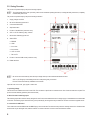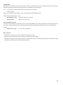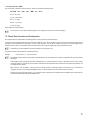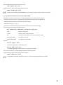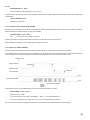
1
OPERATING INSTRUCTIONS Version 10/13 DIN-Rail Module „GX155“ Item No. 40 95 91 1. Table of Contents Page 1. Table of Contents ............................................................................................................................................................................ 2 2. Introduction ..................................................................................................................................................................................... 4 2.1 2.2 2.3. 2.4. Intended Use ..................................................................................................................................................................................... 4 Scope of Delivery .............................................................................................................................................................................. 5 Explanation of Symbols ..................................................................................................................................................................... 5 Safety Information ............................................................................................................................................................................. 5 3. General Notes .................................................................................................................................................................................. 7 3.1. 3.2. 3.3. General Descriptions ......................................................................................................................................................................... 7 Casing Overview ............................................................................................................................................................................... 8 Notes on Use ................................................................................................................................................................................... 10 4. Commissioning - First Steps ........................................................................................................................................................ 11 4.1. 4.2. Changing the PIN Code to „1513“ ................................................................................................................................................... 11 SIM Card Insertion .......................................................................................................................................................................... 11 5. Configuration via Text Message .................................................................................................................................................. 12 5.1. Introduction to the Command Format .............................................................................................................................................. 12 6. Operating Mode and Special Commands .................................................................................................................................... 14 7. Function Descriptions .................................................................................................................................................................. 15 7.1. 7.1.1. 7.1.2. 7.1.3. 7.1.4. 7.1.5 7.2. 7.2.1. 7.2.2. 7.3. 7.3.1. 7.3.2. 7.4. 7.4.1. 7.4.2. 7.4.3. 7.5. 7.5.1. 7.5.2. 7.6. 7.6.1. 7.6.2. 7.6.3. 7.6.4. General Configuration Commands .................................................................................................................................................. 15 Changing the PIN Code (PIN) ......................................................................................................................................................... 15 Changing the Device Name (NAME) ............................................................................................................................................... 15 Names for In- and Outputs .............................................................................................................................................................. 16 Setting the Language (LANGUAGE) ............................................................................................................................................... 16 Setting the Time (TIME) .................................................................................................................................................................. 17 Phone Book Function and Configuration ......................................................................................................................................... 17 Administration of Phone Book (TEL, TELALL) ................................................................................................................................ 18 Group Management (G1, G2, G3, G4, G5) ..................................................................................................................................... 20 Switching Inputs 230 V and 32 V ..................................................................................................................................................... 22 Configuration of the Switching Inputs (IN1, IN2, IN3, IN4, IN5) ....................................................................................................... 22 Configuration Maintenance Timer/Counter (TIME, COUNT) ........................................................................................................... 23 Relay Outputs .................................................................................................................................................................................. 24 Direct Switching (OUT1, OUT2, OUT3) .......................................................................................................................................... 24 Switching at Incoming Call (INCALL1, INCALL2, INCALL3) ........................................................................................................... 24 Switching At Alarm (ALARM) ........................................................................................................................................................... 25 Further Sensors ............................................................................................................................................................................... 26 Internal Temperature Measurement (TEMP) ................................................................................................................................... 26 Top Cover Sensor (TOPCOVER) .................................................................................................................................................... 26 Other Functions ............................................................................................................................................................................... 27 Newsletter Function (SMSNEWS) ................................................................................................................................................... 27 Forwarding (SMSFORWARD) ......................................................................................................................................................... 27 Call INCALL Function (CALLINCALL) ............................................................................................................................................. 28 Send SMS Command (OUTSMS) ................................................................................................................................................... 28 2 Page 7.7. 7.7.1. 7.7.2. 7.7.3. 7.8. 7.9. 7.9.1. System Functions ............................................................................................................................................................................ 28 Time between Two Alarm Messages (IDLEALARM) ....................................................................................................................... 28 Time between Relay Switching (RELAYTIME) ................................................................................................................................ 28 Hysteresis for TEMP (HYSTEMP) ................................................................................................................................................... 28 Reset ............................................................................................................................................................................................... 30 Factory Settings .............................................................................................................................................................................. 30 Factory Reset (SETUP) ................................................................................................................................................................... 30 8. RS485-Interface ............................................................................................................................................................................. 31 9. Other Functions ............................................................................................................................................................................. 31 10. Maintenance ................................................................................................................................................................................... 31 11. Disposal ......................................................................................................................................................................................... 31 12. Declaration of Conformity (DOC) ................................................................................................................................................. 31 13. Technical Data ............................................................................................................................................................................... 32 3 2. Introduction Dear Customer, thank you for purchasing this product. This product complies with the statutory national and European requirements. These operating instructions are part of this product. They contain important notes on commissioning and handling. Also consider this if you pass on the product to any third party. Therefore, retain these operating instructions for reference! All company names and product names are trademarks of their respective owners. All rights reserved. If there are any technical questions, contact: Tel. no.: +49 9604 / 40 88 80 Fax. no.: +49 9604 / 40 88 48 E-mail: [email protected] Mon. to Thur. 8.00am to 4.30pm Fri. 8.00am to 2.00pm 2.1 Intended Use This product is primarily intended for home and commercial use, as well as for associations. The product is installed on a top-hat rail according to DIN EN 50022 (carrying rail, DIN-RAIL). The voltage supply is provided via fixed wiring to the mains (230 V/AC, 50 Hz) with the corresponding protection (see technical data). The corresponding mains unit is already built into the product. The installation must only be performed by a specialist. Generally, the device must be powered down before changing the wiring. The product has three exchange relays for the 230 V-/400 V-range. Different phases can be switched, but switching of rotary current encoders is not intended for (the relays are not warranted to switch at the same time). The relays must be protected from overload by an external protection device according to the specification from the technical data. There is only a functional separation between the relays. Therefore, mixed operation of mains voltage and low protective voltage is not permitted. Mixed operation of industrial, commercial and home areas is not permitted either. There are 3x 230 V-switching inputs to monitor voltage supply of subdistributions and devices. All three voltage inputs share the same neutral conductor but are galvanically insulated against the voltage supply input. There are also two galvanically insulated switching inputs (max. 32 V) for monitoring of, e.g., a PLC voltage supply. Only products that are either listed as accessories on the website for the product or that are indicated accordingly in the product operating instructions must be connected to the optional RS485 interface via RJ plug. The total cable length must not exceed 3 m and must not be placed along current-conducting lines. A common SIM card is required to operate the product (not enclosed). Observe all safety information in these operating instructions! They contain important information on handling of the product. You should also heed the additional safety instructions in each chapter of these instructions. 4 2.2 Scope of Delivery The product’s scope of delivery includes the following components: • GX155 • External antenna with 3 m cable • Brief Instructions • CD with operating instructions 2.3. Explanation of Symbols This symbol is used when your health is at risk, e.g. from an electric shock. The symbol with the exclamation mark points out particular dangers associated with handling, function or operation. The „Hand“ symbol indicates special advice and operating information. 2.4. Safety Information Please read the operating instructions completely before commissioning. They contain important information for correct operation. The product must only be installed in your electrical installation via a corresponding specialist. There is a fatal danger from electrical shock in case of improper work at the mains voltage! In case of damage caused by non-compliance with these operating instructions, the warranty/guarantee will expire. We do not assume liability for any consequential damage. Nor do we assume any liability for damage to property or personal injury caused by improper use or failure to observe the safety instructions. In such cases the warranty/guarantee will expire. • Ensure proper commissioning of the system. Observe the operating instructions for it. • Consult an expert when in doubt as to the operation, the safety or the connection of the system. • When handling products that may come into contact with electric voltage, observe the valid VDE regulations, especially VDE 0100, VDE 0550/0551, VDE 0700, VDE 0711 and VDE 0860. • A device for all-pin separation from the mains voltage must be provided on the installation side (e.g. FI circuit breaker). • The module must only be operated after it has been installed touch-proof. • The power/voltage must be switched off in the installation area when installing. All wiring work must be performed with the voltage/ power switched off. • Before each setup, check your product and its cables for damage. If it can be assumed that safe operation is no longer possible, the device must be turned off and precautions are to be taken to ensure that it is not used unintentionally. It can be assumed that safe operation is no longer possible if: - the product is visibly damaged - the product no longer functions - the product was stored under unfavourable conditions for an extended period of time or - if it was subjected to heavy stress during transport. • All system components left the factory in perfect condition in terms of safety engineering. The user must observe the safety instructions and warnings contained in these operating instructions to preserve this condition and to ensure safe operation. 5 • This partial product is equipped with highly integrated components. Electronic components are very sensitive to electrostatic discharge. Therefore, please do not touch any metal contacts and in particular no plug sockets. • The product must not become damp or wet. • Do not expose the device to any high temperatures, dripping or splashing water, heavy mechanical stress or strong vibrations. • Do not operate the product in rooms or under unfavourable conditions where combustible gases, vapours or dust are or may be present. There is a danger of explosion! • For safety and licensing reasons (CE), unauthorised conversion and/or modification of the system is not permitted. • At industrial sites, the accident prevention regulations of the association of the industrial workers’ societies for electrical equipment and utilities must be followed. • In schools, training centres, computer and self-help workshops, handling of technical devices must be supervised by trained personnel in a responsible manner. • Do not leave the packaging material lying around carelessly since such materials can become dangerous toys in the hands of children. • Use other than that described can lead to damage to the product and may involve additional risks such as, for example, short circuit, fire, electric shock, etc. • The system only serves to trigger alarms but does not relieve the user from his diligence obligation. • Also observe the additional safety information in the individual chapters of these instructions. Special safety information: • Only 230 V/400 V or only protective low voltages must be switched at the relays. Mixed operating is expressly forbidden. There is danger to life from electric shock! • The relays must be secured against overload by an external protective device. For the required protective devices, see chapter „Technical Data“ at the end of these operating instructions. • The cable length at the optional RS485-interface must not exceed 3 m in total and must not be placed along live 230 V lines. • Switching inputs: - The maximum voltage of 32 V must not be exceeded - The lines with 32 V must not be placed along lines with 230 V • All terminals must only be used with wire-end sleeves. 6 3. General Notes These instructions describe the function and operation at the time of print (see date on the top right of the first page). Changes that serve product improvement can be performed at any time by Conrad. The most recent operating instructions will be provided on the associated product page on www.conrad.com in a timely manner. The product has an update function. Please use the update function when you find a note or new product versions of the firmware on the associated product page at www.conrad.com. The firmware update process is connected to risks. If the update process is impaired, this may damage the product and replacement may be required. This risk and the connected costs for removal and failure shall be assumed by the client. Therefore, the update function should only be used to remove an error. Due to the complexity of the product, error and mistakes are reserved. 3.1. General Descriptions The product can be used to permit a group of up to 50 participants to switch the relays free of charge (by calling) and using the consumers wired to them (e.g. door openers). Three 230 V and two 32 V switching inputs may monitor consumers and voltage. Their condition changes are reported to the user by alarm SMS. There also is a „newsletter“ function that forwards a message to the product to a specific partial group. Possible areas of application are: • Free consumption control via the phone number (INCALL) • Remote controlling and monitoring of consumers • Informing groups via SMS • Maintenance timer or counter with deactivation function when exceeding the maximum maintenance time Optionally, there is the operation of EMAIL dispatch as well. If the requirements are met, further EMAIL recipients can be entered for the same messages as for SMS. The prices depend on the data rate of the mobile phone card. The production has an optional RS485 interface. Function scope and supported devices are communicated in the further operating instructions. Only basic functions are described in these operating instructions. • These instructions assume the functional scope at the time of print. The option of the firmware update means that there may be new functions available that are then provided via new operating instructions or notice sheets online. • All text message answer examples are to be understood symbolically. Actual implementation may vary. The examples should only show the information on the format and writing to be expected. 7 3.2. Casing Overview The product is explained step by step in the following chapters. To ensure that the device is set up correctly, make sure to read these operating instructions, including the safety instructions, completely and attentively before use. The product is explained step by step in the following illustration: 1. Supply voltage: 230 V/AC 2. IN1 to IN3: Switching inputs 230 V 3. Connection GSM aerial 4. Stop/reset button 5. Position of the SIM card (under the cover) 6. OUT1 to OUT3: Switching relay, switcher 7. IN4 and IN5: Switching inputs 32 V 8. Status LEDs a. ERROR b. GSM c. IN1 to IN3 d. IN4 and IN5 e. OUT1 to OUT3 f. RX and TX 9. Position of the mini USB socket (under the cover) 10. RS485 interface IN1 to IN5 are lit automatically when the input voltage at the input has exceeded the threshold value. OUT1 to OUT3 light up automatically when the corresponding relay is switched. RX and TX flash automatically at RS485 communication. Open the front cover on left, right, upper or lower side. 1. Operating Voltage The GX155 has an installed mains unit for 230 V/AC. The connection is performed via screw terminals. Use of wire-end sleeves is required. The product must be externally protected (see technical data) 2. IN1 to IN3: 230 V-switching inputs The switching inputs IN1 to IN3 are directly designed for 230 V and should detect the status of voltage supply of subdistributions and switchable consumers. All switching inputs share the same ground potential (N) but are galvanically insulated from all other connections together with N. 3. Connection for GSM aerial This is where the enclosed GSM aerial with MMCX plug is to be connected. The aerial must be pushed in vertically without force. Otherwise the aerial socket may be damaged. Note, that the antenna is mounted outside of an switch control box/electrical cabinet. 8 4. STOP button This button switches off all relays and blocks them against activation. This BLOCK mode is recognised by the permanently lit „ERROR“ LED. To „release“ it, the button must be pushed for at least 3 seconds. Pushing and holding for more than 5 seconds leads to a reset. For more information on this, see chapters „Reset“ and „Factory Reset“. 5. SIM card A common, released SIM card is required. The front cover must be removed for insertion. The SIM card holder is located below that. Removal of the cover is recognised by a sensor and leads to immediate SMS alarm (if set and activated). Observe chapter 4 regarding the SIM PIN. 6. OUT1 to OUT3: Change relay 3x change relays are available to switch signals and consumers. These may be directly switched via SMS or the INCALL function. The relays can be blocked (button) and secured against too-quick switching („RELAYTIME“). The technical data and safety notes must be observed. 7. IN4 and IN5: Max. 32 V switching inputs The switching inputs serve,e.g., monitoring of voltage supplies (example PLC controls). The threshold value is far below the 32 V maximum voltage. For more details, see the technical data. 8. LEDs Most LEDs, such as IN1 to IN5, OUT1 to OUT3 and RX/TX light up automatically according to the current status of in-/output. The GSM-LED is automatically controlled by the GSM module and has the following conditions: - off: GSM is switched off - Lit: search for GSM network, not connected - flashes every 3 seconds: GSM network found and successfully logged in - flashes every second: A call is made (in- and outgoing), e.g. in the INCALL function The error-LED has several signalling tasks: - off: regular condition - Continually lit: „BLOCK MODE“: The relays cannot switch - Continually flashing: An error in the GSM communication was found (SIM PIN?) - Flashes 1x: SMS was received/sent - other signals are described in the chapters „Reset“ and „Factory Reset“ 9. Mini-USB port This is only accessible after removal of the front plate. This interface can be used to configure the product with a PC software and install new firmware updates. Observe the following general notes. For the first setting of parameters, the product can also be operated without external power supply, via USB only. However, no INx or OUTx interfaces are available via USB. 10. RS485-Interface This interface can be used to connect the GX155 to operational accessories and assess it through this. There is also the option of controlling the GX155 via this interface. Optional accessories are offered via the product website at www.conrad.com. 9 3.3. Notes on Use • There is no prescribed assembly position. • When using the USB socket, observe that the cable is long enough. Lateral forces on the plugged-in plugs can lever the sockets from the PCB and thus cause irreparable damage, loss of warranty/guarantee! • To warrant the device function, choose a site of use where the GMS network reception is as good as possible. • The product must not be subject to continuous strong vibrations (e.g. vibrating machines, direct motor/chassis contact). • The product is not protected against weather and therefore must be installed inside. • Use of wire-end sleeves is generally intended for. • The external cables must be kept as short as possible and remaining line lengths must not be coiled. • Too-strong temperature fluctuations may lead to temporary impairment and require manual „Reset“ in extreme cases. • The product is not intended for the „Safety“ area and also does not correspond to any SIL/ASIL level. 10 4. Commissioning - First Steps Prior to commissioning of the product, check whether it is generally suited for the intended application! In case of doubt, always contact a specialist, expert or the manufacturer of the product used! The following is needed for operation and configuration of the device: • A common mobile phone with its own SIM card for configuration and control of the GX155 and to change the SIM-PIN of the device SIM card • An additional device SIM card for the GX155 The following is required for confirmation via PC and for any firmware update: • Mini USB cable • PC or notebook with Windows operating system and at least one USB2.0-port • Officially released PC software (see download area on the product website at www.conrad.com) 4.1. Changing the PIN Code to „1513“ Every SIM card has a PIN code. Because this GSM product uses its own PIN processing, the SIM card PIN code must be changed to that of the product. The following steps are required for this: • The SIM card intended for the product must be inserted in any mobile phone. • According to the operating instructions of the mobile phone, the PIN code must be changed to 1513. • The SIM card with the changed PIN code must be removed from the mobile phone. • The SIM card with the changed PIN code can now be inserted into the product. 4.2. SIM Card Insertion The SIM card with the PIN number „1513“ must be inserted in the intended SIM card holder. The module can be supplied via the USB socket for the first configuration. Note, that not the complete GSM-functions are available via USB. After connection of the voltage supply, the module will start up automatically. After inserting the SIM card, the the GSM LED is lit (network search); after a few seconds, the GSM-LED should start flashing (network found, device ready for operation). If the GSM LED does not start to flash after a few minutes, there is no connection to the GSM network. In this case, the network quality and function of the SIM card must be inspected at the product site with a separate mobile phone. If the GSM signal is weak, the USB port energy may not be sufficient. In this case, the product must be operated with an external voltage supply. If an error occurs while connection to the GSM network is established, it is signalled with the error LED. In this case, activate the front button for more than 5 seconds. Furthermore, the SIM card (PIN/PUK/activation) must be inspected and the receiver quality at the device position must be verified with a separate mobile phone. If the device used to be used with another SIM card, there is the option of the PIN number in the product being changed and now no longer matching the factory setting „1513“. In this case, the device must be reset to factory settings (section „Factory Reset“). The SIM card may have been locked in the meantime and must be unlocked with the PUK. In this case, use a separate mobile phone and unlock the SIM card. 11 5. Configuration via Text Message To receive the full functional scope of the product, it must be configured first. The entire configuration is performed by simple text message commands you send to the product (the phone number of the SIM card in the product) from your mobile phone. This method makes it possible to activate, deactivate or change the settings of your device from anywhere. Alternatively, the product can be configured via the USB interface using PC software (available via www.conrad.com). • These operating instructions do not deal with configuration via PC software. This only describes how the product can be controlled with a mobile phone, without any other aids. For the sake of completeness, commands that are only available via USB are listed as well. They are marked specifically. • To protect from unauthorised access, the product generally reacts to authenticated messages only. In a text message, you authenticate yourself by including the correct SIM PIN of the GX product (not the one of the mobile phone on which the text message was written). • For your own safety, the SIM PIN number must be changed under all circumstances after commissioning of the product. This is described in more detail in the chapter corresponding to the command. 5.1. Introduction to the Command Format The text message to program the device is set up according to the following chart: <ACTION> <FUNCTION> <PARAMETER1> SET TEL +49177556644221 RESET <…> <#PIN> Examples: #1513 (phone book) INCALL1 #1513 (no calls) TEST IN1 #1513 (request IN1) ENABLE ALARM #1513 (alarms on) DISABLE ALARM #1513 (alarms off) Important: Every text message sent to the device must end with the PIN set as protection. Without „#PIN“ at the end of the text message, it is discarded and no answering text message will be generated! The individual words and parameters must be separated by a space each. ACTION: The following action can be determined: SET = switch on / activate / configure RESET = switch off / deactivate / default settings TEST = test / check / request FUNCTION: This is used to select the function you want to change or perform: TEL = Create phone book entry NAME = Device name INCALL1 = Configuration INCALL function (free-of-charge switching) 12 PARAMETERS: Parameters are not required for every function and action. Therefore, most „Reset“ actions have no parameters while „Set“ actions without parameters are rather rare (what should be set to which value). A parameter may be the following: List: The customer may choose a parameter from a pre-defined list, e.g.: DE, EN Writing: <DE/EN> Number: An integer without decimal digits, e.g.: 60 = time [minutes] (SET IDLEALARM 60 #1513) Examples: (if the PIN of the device is 1513) SET G3 INCALL1 #1513 Group 3 can switch OUT1 (=INCALL1) SET OUT1 #1513 Switches on the OUT1 relay. Note on the RESET command: If a function is to be switched off or reset due to an error, the corresponding RESET action must be used with the corresponding function word! This action is universally applicable to all functions/text message commands and resets the corresponding function to the default settings. Example: RESET OUT2 #1513 The OUT2 relay is switched off. More information: • Capitalisation is not relevant; you may use capital and small letters as you wish. • Every new command of the same function (2nd word) will overwrite the previous settings. • After every text message command, the device will return a test message answer to confirm the programming (if the PIN in the text message command was correct and phone number conveying is activated). 13 6. Operating Mode and Special Commands The alarm mode: The most important operating mode is alarm mode. Only when it is activated (mode „ALARM ENABLE“) will the GSM module independently perform actions like sending of text messages or switching the outputs. When the alarm mode is disabled („ALARM DISABLE“), the product will only react to customer actions (text message command, etc…). If the product does not react as desired, it can be switched into a secure condition with this command. Due to this importance, the command deliberately deviates from the regular command format from the previous chapter. ALARM ENABLE #1513 ALARM DISABLE #1513 BLOCK mode: BLOCK mode sets whether the relays may switch or not. When BLOCK is activated, all relays are deactivated at once and can no longer be activated until BLOCK is deactivated. SET BLOCK #1513 RESET BLOCK #1513 The front button of the GX155 also switches the BLOCK mode. One push of a button activates the BLOCK mode at once. The button must be pushed for 3 seconds to deactivate. Sending of a text message and operation of the button are equal in rank. The current condition of BLOCK is signalled with the „ERROR“ LED. When the mode is active, the red LED remains lit. Alternatively, the current condition can be determined with the STATUS SMS. Status display: The STATUS command is used to get an overview of all the important conditions, settings and modes at once. The answer summarises all the important information. Therefore, this command deviates from the general command format. STATUS #1513 An example for an answer is presented in the following (deviations possible depending on firmware version). Answer: GX155 1.00 Product name, firmware version Alarm: OFF Current alarm mode GSM: 78% GSM signal strength Temp: 20.5C Device temperature IN1: low Current level at the switching input IN1 IN2: low IN3: low IN4: low IN5: low OUT1: OFF Current switching condition at the OUT1 relay OUT2: OFF OUT3: OFF BLOCK: OFF 14 Current status for the BLOCK mode 7. Functional Descriptions In the following examples, it is assumed that the PIN of the SIM card in the device is „1513“. 7.1. General Configuration Commands This sub-chapter describes all general configuration commands. 7.1.1. Changing the PIN Code (PIN) To secure the product against unauthorised access, the standard PIN „1513“ may be set to any other number. Change the PIN code as follows: SET PIN <new PIN> #<old PIN> Example: Changing old PIN 1513 to new PIN 1234: SET PIN 1234 #1513 For every new text message command, the new PIN code now has to be appended preceded by a (#) sign. If the wrong PIN code is entered or the PIN code is not sent, you will not receive an answering text message. Changing of the PIN code will change both the settings of product PIN and the PIN code of the SIM card! The PIN code always has 4 digits. There is no TEST action for this function. If the PIN code is lost (lost or forgotten), the product can be reset to factory settings (see chapter „Factory Settings“). All settings will be lost when resetting! Then the device must be set again. Resetting the device to factory settings will not affect the SIM card. The PIN code of the SIM card is not changed. 7.1.2. Changing the Device Name (NAME) If several products are operated at the same time, it is recommended to assign a different name to each device. This makes it possible to assign alarm messages to the correct device. The device name is changed as follows: SET NAME <new name> #1513 Example: Renaming to „NEWNAME“: SET NAME NEWNAME #1513 The device name has a maximum length of 15 characters. The following command reads the current device name: TEST NAME #1513 The following command resets the original device name: RESET NAME # 1513 15 7.1.3. Names for In- and Outputs A separate name can be assigned for each switching input (IN1 to IN5) and each relay (OUT1 to OUT3). The names are mainly used for alarm messages, but can later be used to determine the correct relay to be switched as well. The names generally do not affect the commands. Switching OUT1 is continued to be performed with SET OUT1 #<PIN>. The names are set as follows: SET NAMEIN1 <10 characters max> #<PIN> Name switching input IN1 SET NAMEIN2 <10 characters max> #<PIN> Name switching input IN2 SET NAMEIN3 <10 characters max> #<PIN> Name switching input IN3 SET NAMEIN4 <10 characters max> #<PIN> Name switching input IN4 SET NAMEIN5 <10 characters max> #<PIN> Name switching input IN5 SET NAMEOUT1 <10 characters max> #<PIN> Name relay OUT1 SET NAMEOUT2 <10 characters max> #<PIN> Name relay OUT2 SET NAMEOUT3 <10 characters max> #<PIN> Name relay OUT3 Only regular characters a-z, A-Z must be used No special characters must be used. Spaces may be used but are counted as characters. TEST displays the names. RESET deletes the individual name again. There also is a command with which all names, including device names (SET NAME) can be deleted: RESET NAMEALL #<PIN> 7.1.4. Setting the Language (LANGUAGE) This command sets the product language. The set language is used for alarm messages and error messages. The languages German (DE) and English (EN) are available. SET LANGUAGE <new language setting> #1513 Example: SET LANGUAGE DE #1513 The following command reads the currently set language: TEST LANGUAGE #1513 The device may be reset to the default (DE) with the following command. RESET LANGUAGE #1513 16 The command and text message answer language is not changed. 7.1.5. Setting the Time (TIME) The current time is needed for special functions. The time is set with the following value: SET TIME <hh> <mm> <DD> <MM> <YY> #1513 hh: 00 - 23 (hours) mm: 00 - 59 (minutes) DD: 01 - 31 (day) MM: 01 - 12 (month) YY: 00 - 95 (year) TEST displays the current setting. The clock has a small, internal supporting battery. It is charged but only used for short-term bridging. 7.2. Phone Book Function and Configuration This chapter treats the administration and setting options for the phone book and authorisations. The product can be configured with many phone numbers and emails. They can be grouped to improve overview. The individual groups can be configured in their authorisation for switching or for use of other functions. The number of numbers and groups may change depending on firmware version in future. The firmware version had 50 memory slots for phone numbers with 5 groups at the time of print. Authorisations are not assigned to the phone numbers but to the groups only. The phone numbers must be entered in international format. Example: 0177/12131415 -> +4917712131415 Most GSM providers submit incoming calls in the international format. Therefore, the numbers are needed in this format to warrant recognition. Some GSM providers (specifically Austria and Switzerland) only submit the phone numbers in the national format, which makes recognition (INCALL) more difficult. In this case the national format must be saved in the phone book. This makes it impossible to use any foreign phone numbers. Many functions, such as INCALL, require that the own phone number is transmitted (caller ID transmission). If you activate the „incognito“ function of your mobile phone/GSM provider, you will be unable to use many of the product’s functions. The security of incoming call recognition, e.g., for access control corresponds to the safety level of the GSM provider. The product only verifies the number transmitted by the GSM provider. 17 7.2.1. Administration of Phone Book (TEL, TELALL) The phone book: The phone book is administrated by the product. This means that the module independently selects the memory slot for a new phone number. Every time a phone number is deleted, the memory is reorganised so that there will not be any empty memory slots. For the customer to retain the overview, a name can be stored for every number. The command to configure a new number therefore looks as follows: SET TEL [< phone number >] [<group>] [<name>] #1513 Phone Number: See description in the previous chapter Group: Direct assignment to a specific group. If none is indicated, G1 is assumed automatically. Name: Max. 10 characters, no spaces, will be shortened automatically A few examples: SET TEL +49112233 G3 VeryImportantPerson #1513 Saves phone numbers for group 3 and the name „VeryImport“ (name is shortened to 10 characters, see above). SET TEL G4 #1513 Saves your own number of group 4 without name. SET TEL #1513 Saves your own number of group 1 without name SET TEL AnotherImportantPerson #1513 Saves phone numbers for group 1 and the name „AnotherImp“ (name is shortened to 10 characters, see above). The answer will be a detailed description of what was saved. A possible example is: GX155 1.00 Tel15_Name: MR_J Tel15_No: +49112233… Tel15_Group: G1 To change the name, number or group association subsequently, you can send the following commands: SET TELNAME <Nr> <Name> #1513 SET TELNR <Nr> <TelNr> #1513 SET TELGRP <Nr> <new GRP> #1513 Nr: The memory slot number Name: New name, max. 10 characters, no spaces TelNr: Phone number in international format (see below) New GRP: The group names G1 to G5. Saving the same number with the same group is not prevented. The number will receive the same text messages the corresponding number of times. Multiple saving of the phone number in the phone book is sensible when it is assigned to different groups. This phone number will receive the rights of all groups but also several alarm messages and NEWS. 18 You need this command for an overview of the phone book: TEST TEL #1513 The module will then send out the following overview: GX155 1.00 Tel_Count: 15/50 Grp1_Count: 4 Grp2_Count: 7 Grp3_Count: 2 Grp4_Count: 1 Grp5_Count: 1 To learn which phone numbers (memory slot numbers) belong to a specific group: TEST TEL <Grp> #1513 Example: TEST TEL G5 #1513 GX155 1.00 Grp: G5 Member 01, 03, 04, 05, 07, 11, 12, 15, 16, 18, 21, 22 To learn what phone number is placed in a specific memory slot: TEST TEL 11 #1513 If an empty memory slot was selected, the following will be returned: GX155 1.00 Tel11 Name: Tel11 Nr: Tel11 Group: G1 To learn the memory slots on which a phone number was saved and which groups it therefore belongs to: TEST TELNUMBER +4915112233.. #1513 A possible answer would be: GX155 1.00 TelNr: +4915112233.. TelPos: 1, 5, 8, 10 TelGrps: G1, G2, G3, G5 19 The following command deletes a memory slot: RESET TEL <Nr> #1513 Nr: The memory slot number to be deleted The following command deletes a series of numbers: RESET TEL <Nr> to <Nr> #1513 If a specific phone number is to be deleted: RESET TELNUMBER <TelNr> #1513 Observe that deletion of a memory slot will cause the memory to be resorted. When 4 numbers are saved and the 2nd number is deleted, the 3rd and 4th move up one position. This is why names need to be assigned. Use the following command to delete the entire memory: RESET TELALL #1513 USB and RS485 also offer the command TEST TELALL #1513, which returns the entire phone book with position number, name, phone number and group. 7.2.2. Group Management (G1, G2, G3, G4, G5) Group administration was introduced for better administration of many phone numbers. The groups are assigned rights to specific actions and/ or receipt of specific information. In the firmware version at the time of print, 5 groups are available with the first group G1 automatically being used as „Default“ for new numbers. Different authorisations may be assigned to and revoked for each group. The following authorisations options are available at the time of print: ALARMSMS: In the „ALARM ENABLE“ mode, this group is sent alarm messages. For example, the maintenance counter for a switching input can be set so that an alarm is generated after the end of a maintenance interval. The alarm text message would be sent to everyone in the group. NEWS: In the „ALARM ENABLE“ mode, this group is sent the „NEWSLETTER“ text message. Everyone who knows the PIN number can send a message to the product that is then forwarded to all NEWS group members. For more on this, see the chapter on the function „NEWS“. SMSFORWARD: The FORWARD function forwards unknown messages received by the product to this group. For example, the administrator of the product receives the message from the GSM provider that the credit on the PrePaid card is used up. Recipients of alarm messages may also request being removed from the phone book. For more on this, see the chapter „FORWARD“. INCALL1, INCALL2, INCALL3: The product has three exchange relays OUT1 to OUT3. The INCALL function was developed to be able to switch freely of charge by calling (call is not accepted but rejected). If, e.g., group G3 is to be authorised for INCALL2, every member may switch the relay, e.g. for 5 seconds, by calling (depending on setting). For more information on this subject, see the chapter on INCALL. The following authorisations are assigned to the groups in the default settings of the device: G1: NEWS and ALARMSMS G2: INCALL1 (INCALL is set to 3 seconds) G3: INCALL2 G4: INCALL3 G5: SMSFORWARD 20 This command is needed to set the group configuration: SET <G1/G2/…/G5> <ALARMSMS/SMSFORWARD/NEWS/INCALLn> #1513 Examples: SET G1 ALARMSMS #1513 SET G2 INCALL1 #1513 SET G3 INCALL2 ALARMSMS INCALL3 NEWS #1513 SET G4 NEWS SMSFORWARD #1513 SET G5 SMSFORWARD #1513 The same applies for resetting of an authorisation. RESET must be prefixed for this. All authorisations that are then specified are deactivated. RESET <G1/G2/…/G5> <ALARMSMS/SMSFORWARD/NEWS/INCALLn> #1513 Use the following command to review the current authorisations: TEST <G1/G2/…./Gn> #1513 The following command deletes all authorisations: RESET <G1/G2/…./Gn> #1513 21 7.3. Switching Inputs 230 V and 32 V All switching inputs are disconnected from areas of the GSM PCB that may be touched securely by optocouples. The separation between the 230 V switching inputs and the internal low safety voltage is designed for overvoltage category III and contamination degree 2 according to EN 60664-1. Under consideration of the conditions named, the industrial installations may be used. Observe the generally common safety rules when opening the front flap and during installation or connection work. The 230 V switching inputs share the same neutral conductor but are galvanically insulated against all other connections together. The 32 V-switching inputs are galvanically insulted against each other and the GSM PCB. The maximum voltage between the two pins must not exceed 32 V. The current status of the switching inputs is automatically signalled via the LEDs and indicated in the STATUS-SMS. There is no difference between the inputs where configuration is concerned. Observe the following when connecting the 230 V switching inputs: • Compliance with the safety notes • Wire end sleeves must be used Line cross-section connections IN1 - IN3: 2.5 mm² Line cross-section connections IN4 - IN5: 1,5 mm² • IN1 to IN3 must be on the same N-potential. • The voltage areas for high and low are found in the technical data. All switching inputs (IN1 to IN5) and all relays (OUT1 to OUT3) have a delay of at least 1 and no more than 3 seconds. This delay time must be observed for each condition change. This applies specifically for time measurements. 7.3.1. Configuration of the Switching Inputs (IN1, IN2, IN3, IN4, IN5) The switching inputs are present to determine misconduct. In the simplest case, e.g. activation (Low -> High = LH), deactivation (High -> Low = HL) or toggling (Low -> High -> Low = LHL) may be recognised and an alarm be generated. Alarming via the switching input is deactivated by default. The following command is needed for activating: SET <IN1/IN2/…/INn> <OFF/LH/HL/LHL> [<Time>] #1513 TIME: 1 to 255 seconds, optional parameter (the time has a tolerance of +/- 1 s) The optional parameter <TIME> can set that an alarm is not triggered at once after the flank but only after a set time. This may be balance out, e.g. interferences. After this command, an overview of the current configuration is returned by text message. GX155 TEMP: 18.0C Min. Temp. OFF Max. Temp. OFF HYSTEMP: 0.2C IN1: OFF IN2: LH IN3: LH IN4: LH IN5: LH 22 The same text message is sent with the same command: TEST <IN1/IN2/…/INn> #1513 All INx-functions are reset to factory settings with the command: RESET <IN1/IN2/…/INn> #1513 With the function ALARM (not ALARM ENABLE) you can instruct the relays to perform an action in case of alarm. 7.3.2. Configuration Maintenance Timer/Counter (TIME, COUNT) Alternatively, the input can also be used to count along operating hours and activation numbers. Observe: • A starting value for both versions is specified by text message and counted down. Alarm is triggered at „0“. • Only switching times in excess of 3 seconds are securely recognised. • Every flank is counted (L -> H, H -> L). • The timer only counts full seconds and may have a delay of up to 3 seconds per switching flank. The following command serves to activate this function: SET <IN1/IN2/…/INn> <TIME/COUNT> <starting value> [INV] #1513 TIME: Seconds counting down COUNT: Activation counter, counts at each flank INV: Can only be used for TIME; counts for LOW, otherwise for HIGH Starting value TIME: 0 to 33,554,431 seconds Starting value COUNT: 1 to 1,048,575 LH-/HL-transfers Examples: SET IN1 COUNT 4 #1513 The alarm is triggered for the 4th switching process. SET IN3 TIME 55 INV #1513 The alarm is triggered after at least 55 seconds in the deactivated condition. The current counter status can usually be determined with the TEST INx-command. All INx-functions are reset to factory settings with the command: RESET <IN1/IN2/…/INn> #1513 The recognition of this status change has a delay of +1 s. For each switching operation this error will add. 23 7.4. Relay Outputs All relay switching inputs are securely insulated from areas of the GSM PCB that may be touched. The separation for safety low-voltage is designed for overvoltage category III and contamination degree 2 according to EN 60664-1. Under consideration of the conditions named, the industrial installations may be used. The relay switching contacts only have a functional insulation against each other. The relay therefore must only switch either mains voltages only or low safety voltages only. Mixed operation (switching mains voltage AND switching safety low voltage) is not permissible. The status of the relays is automatically signalled via the LEDs and indicated in the STATUS-SMS. It should also be observed that all relays deactivate at once and cannot be activated anymore when the BLOCK mode is activated. Observe the following when connecting the 230 V switching inputs: • Compliance with the safety notes • Wire end sleeves must be used • Line cross-section up to 2.5 mm² • The protection class applies only against the internal GSM PCB, not between the relays. • The switching powers are indicated in the technical data. 7.4.1. Direct Switching (OUT1, OUT2, OUT3) All relays can be manually switched by text message at once and without delay. This applies to „ALARM ENABLE“ as well, but not in BLOCK mode. The command is: SET <OUT1/OUT2/OUT3> #1513 Switching on RESET <OUT1/OUT2/OUT3> #1513 Switching off This function can be combined. Therefore the following commands: SET OUT1 #1513, SET OUT2 #1513, SET OUT3 #1513 … and the command: SET OUT1 OUT2 OUT3 #1513 ..will have the same result. 7.4.2. Switching at Incoming Call (INCALL1, INCALL2, INCALL3) The INCALL function is used to permit specific people (phone book, group rights) to switch the relay without causing costs or needing to disclose the PIN. The incoming phone number (transmitted by the GSM-provider and usually in the international format) is compared to the numbers in the phone book during a call. If the number is unknown, the call is rejected at once. If the number is known and switching permitted, the product will wait for a few seconds before rejecting the call. The authorised person receives the information that the device was reached. The following command defines what to do at an INCALL: SET <INCALL1/INCALL2/INCALL3> <TIME> #1513 Time: How long should the relay switch, in seconds Maximum time: 300 seconds Special value: 0 = toggle (switch at every call) To determine the current configuration: TEST <INCALL1/INCALL2/INCALL3> #1513 To deactivate the function again: RESET <INCALL1/INCALL2/INCALL3> #1513 24 • This chapter sets HOW to react. The chapter phone book defines to WHOM to react. This function is only active together. • Only the activation time is defined. If the relay is already on when calling, it remains on and is deactivated after the specified time. • When toggling, the current relay condition is changed. • Cannot be used in BLOCK mode. • Cannot be used for ALARM DISABLE. • The time can be re-triggered by another call by the same or another person. The relay is activated and the timer value set at each call. • RELAYTIME has the higher priority. When the set time is lower, RELAYTIME is used automatically as the switching time. 7.4.3. Switching At Alarm (ALARM) This is a function for the alarm mode. In case of alarm (e.g. IN1 was switched), this command determines what to do in addition to the ALARMSMS and EMAIL. This product permits defining the relays for automatic switching. The command for this is: SET ALARM <OUTx> [<OUTy>] [<OUTz>] [<TIME>] #1513 Time: How long should the relay switch, in seconds Maximum time: 300 seconds Special value/default: 0 = only activation (see below) Examples: SET ALARM OUT1 OUT3 #1513 Since no time was indicated, „0“ is used automatically. The relays 1 and 3 switch at ALARM and remain activated until ALARM DISABLE #1513 is sent. TEST and RESET requests the current confirmation accordingly and resets them to DEFAULT <off>. RELAYTIME has the higher priority. When the set time is lower, RELAYTIME is used automatically as the switching time. 25 7.5. Further Sensors The product also has additional sensors that can be used for alarming. 7.5.1. Internal Temperature Measurement (TEMP) The product has an internal temperature sensor on the GSM PCB that can be used to issue an alarm in case of temperatures that give reason for concern (e.g. less than 0 °C or above +40 °C). However, the intrinsic temperature is measured here instead of the ambience temperature. The command for configuration is: SET TEMP <MIN. Temp.> <MAX. Temp.> #1513 Min. value: -390 (-39.0 °C) Max. value: 850 (+85,0 °C) When using MIN and MAX values, this threshold is deactivated automatically since there is no measured value behind it. The value „MIN. Temp“ must be less than the value „MAX. Temp.“. Example: SET TEMP -10 +225 #1513 An alarm is triggered below -1 °C and above +22.5 °C. TEST and RESET requests the current confirmation accordingly and resets them to DEFAULT <off>. There is another system function that influences this command: HYSTEMP. For more on this, see the corresponding chapter. 7.5.2. Top Cover Sensor (TOPCOVER) To offer the user access to the product for maintenance without having to remove it from the installation, the SIM card and the USB socket are freely accessible after the lid is removed. The product has a light sensor to recognise and alarm unauthorised access. This can be used for alarming once the cap is removed. The command for activation is: SET TOPCOVER [<SMS>] [<Block>] #1513 When using the parameter SMS, an alarm SMS is sent when removing the lid in mode „ALARM ENABLE“. When BLOCK is used, BLOCK mode is activated automatically. Both can be combined. If no parameter is indicated, the function is deactivated (identical with RESET). TEST and RESET requests the current confirmation accordingly and resets them to DEFAULT <off>. 26 7.6. Other Functions This product has a number of other functions in the area of communication. All functions that can still be performed or triggered via text message and call and that have not been described yet are included in this chapter. 7.6.1. Newsletter Function (SMSNEWS) This product was also developed for associations and groups. This function was integrated to keep members up to date on news. A newsletter message to the product is forwarded to all group members. This function is also connected to higher costs. Generally, the following rule applies: Who can send a News text message? Everyone who knows the PIN number. Who receives this text message? Groups with activated NEWS How does the product recognise a News text message? With the command NEWSLETTER: <NEWS> #1513 How can one unsubscribe from NEWS? Not automatically. Therefore, the SMSFORWARD function is recommended. The administrator receives the unsubscription and needs to change the rights (move to another group). Everyone with the PIN can send a newsletter text message: NEWSLETTER: <Text> #1513 Example: NEWSLETTER: Welcome to the NEWSLETTER function of the G155! #1513 All recipients than are shown: GX155 V1.00 Welcome to the NEWSLETTER function of the G155! Only group members with activated NEWSLETTER function receive this message. Example: SET G1 NEWS #1513 activates NEWSLETTER for group G1. The mode „ALARM ENABLE“ is required. Otherwise an „Access Denied“ is replied. 7.6.2. Forwarding (SMSFORWARD) Many customers usually used the predecessor products of the „GX155“ with PrePaid cards. However, automatic charging had to be set for this at all times. This was too insecure for many customers (cost protection). Additionally, it is possible that persons do not want any further alarm messages but are unable to contact the product’s owner. Both problems are removed with the forwarding function. The function has the following parameters: SET SMSFORWARD [TelNr] #1513 TelNr: Phone number to which all incoming text messages are forwarded. If not specified, all group members with the SMSFORWARD authorisation receive the forwarded message. If you want to limit the costs for forwarding, you can choose a single phone number. Since this function is connected to costs, the DEFAULT value is, of course, „OFF“. TEST and RESET requests the current confirmation accordingly and resets them to DEFAULT <off>. 27 7.6.3. Call INCALL Function (CALLINCALL) The CALLINCALL function was developed to trigger an action at another product in case of alarm. This function has the task of triggering the INCALL function of another product in case of alarm. This triggers switching of a remote consumer or alarm siren. SET CALLINCALL <TelNr> [RingCount] #1513 TelNr: Number of another GSM product. RingCount: Optional, how often is it supposed to ring. 1 to 10x This phone number has nothing to do with the phone book and is saved separately. The requirements to the phone number correspond to those of the phone book (international format, etc…). The number of ringtones is theoretic and depends on the provider of the target number. TEST and RESET requests the current confirmation accordingly and resets them to DEFAULT <off>. 7.6.4. Send SMS Command (OUTSMS) A text message can be sent out automatically to trigger an action at another product in case of alarm. The text message content is adjusted to the regular size of a GX product command. The command for this is: SET OUTSMS <TelNr> <TEXT> #1513 TelNr: Number of another GSM product. Text: The text message content including spaces. Max. length: 59 characters. Example: SET OUTSMS +49112233… SET OUT3 #1234 #1513 Now the relay in the product with phone number +49112233… is set when an alarm is triggered. This phone number has nothing to do with the phone book and is saved separately. The requirements to the phone number correspond to those of the phone book (international format, etc…). TEST and RESET requests the current confirmation accordingly and resets them to DEFAULT <off>. 7.7. System Functions This chapter describes technically sophisticated functions. The factory settings are already set for most application areas. Therefore, we recommend only adjusting these parameters in the respective application cases. If the product has any malfunctions, first reset the factory settings. If you need to contact the hotline, ensure that the device is back in its standard configuration (factory settings). 7.7.1. Time between Two Alarm Messages (IDLEALARM) In case of alarm, the product will send an alarm message. From this time onwards, a time window (idle window) starts for this input ; during this time, no other alarm can be triggered. This reduces the text message costs caused by an incorrectly set product. Every alarm source has its own idle time window. A value of 5 minutes is set in the factory for the idle time window. SET IDLEALARM <Time> #1513 Time: 28 1 - 240 minutes Example: SET IDLEALARM 15 #1513 The period between alarm messages is now 15 minutes. In this time window, you will not receive any new messages on alarm situation changes. Within this period, however, every user is able to check his parameters. TEST IDLEALARM #1513 Reading the configuration 7.7.2. Time between Relay Switching (RELAYTIME) Since this product most likely is used to switch complicated consumers, activating and deactivating too quickly may cause damage. Therefore, the time between two condition changes of a relay can be defined: SET RELAYTIME <Time> #1513 Time: 1 - 30 seconds, factory setting = 5 seconds All switching commands during this time window are rejected. Only BLOCK mode has a higher priority. TEST and RESET requests the current configuration accordingly and resets it. 7.7.3. Hysteresis for TEMP (HYSTEMP) The factory settings were already chosen to be suitable for most applications. Changes are only necessary in exceptions. The hysteresis function was developed to prevent undesired alarms. Hysteresis will cause the alarm threshold to change after the hysteresis value is exceeded. This requires the analogue value to enter the permitted area further before the alarm condition stops. Analogue value Upper threshold Hysteresis Measured value Hysteresis Lower threshold Time Alarm with hysteresis Time Alarm without hysteresis These hysteresis values are set independently of the alarm value with the following commands: SET HYSTEMP <value> #1513 Regards function: TEMP The value range for the command is: HYSTEMP 0.....99 (01 = 0.1°C); default setting 0.2°C The value „0“ deactivates this function (at your own risk - too frequent switching processes!) The action TEST for any function displays the current status of all hysteresis values. RESET resets to the basic settings. 29 7.8. Reset To perform a reset, the STOP button at the front of the device must be pushed and held until the red LED starts to flash. The LED will flash until the button is released. 7.9. Factory Settings To reset all settings to factory settings („Factory-Reset“), first push and hold the button STOP. After a few seconds, the red LED will start flashing quickly. A reset is performed after release. Pushing and holding STOP again at once until the red LED flashes slowly causes all settings to be reset to factory settings. The device PIN is also reset to the default #1513! 7.9.1. Factory Reset (SETUP) Alternatively, you can also use a text message command for this. RESET SETUP 12345678 #1513 The figures 1 to 8 serve to verify that this command should actually be triggered. 30 8. RS485 interface The RS485-interface serves remote control and expansion of the product. Only products officially released as accessories are included in the warranty and guarantee. These products are located in the accessories list on the product page at www.conrad.com. Other devices must not be connected to the interface! 9. Other Functions There are more functions under development. After provision of firmware updates, new operating instructions are provided accordingly in the download area of the product page at www.conrad.com. 10. Maintenance Regularly inspect technical safety of the system, e.g. for damage to the connection lines and sensors. Servicing or repair must only be carried out by a specialist. If it can be assumed that safe operation is no longer possible, the device must be turned off and precautions are to be taken to ensure that it is not used unintentionally. It can be assumed that operation without danger is no longer possible if parts of the device have any visible damage, the system no longer works or severe mechanical stain has occurred. 11. Disposal Dispose of the product according to the applicable statutory provisions at the end of its service life. 12. Declaration of Conformity (DOC) We, Conrad Electronic, Klaus-Conrad-Straße 1, D-92240 Hirschau, hereby declare that this product adheres to the fundamental requirements and the other relevant regulations of the directive 1999/5/EG. The declaration of conformity for this product is available at www.conrad.com. 31 13. Technical Data Installation ....................................................... DIN-RAIL, 35 mm Operating voltage ............................................ 100 - 240 V/AC, 50/60 Hz Power input ..................................................... max. 30 mA Power consumption ......................................... average: 3 W External fuses recommended .......................... 2 A, 250 V Internal battery (time) ...................................... Lithium battery, cannot be replaced Switching power (external fuse required) ........ 250 V/AC, 16 A (Ohmic load) 250 V/AC, 3 A (inductive load) 24 V/DC, 16 A Important note OUT1 to OUT3: Only functional separation (observe notes in the operating instructions!) Input IN1 to IN3 ............................................... Logical Low/L at 0 to 5 V/AC Logical High/H at 15 V/AC to max. 250 V/AC Note: IN1-3, OUT1-3, mains unit ..................... Overvoltage category III, 300 V Degree of contamination: 2 Voltage resistance: 4000 V max. Inputs IN4 and IN5 .......................................... Logical Low/L at 0 to 1.0 V/DC Logical High/H at 1.5 V/DC to max. 32 V/DC Internal temperature sensor ............................ -40 °C to +125 °C, accuracy: +/- 2 °C RS485-voltage supply ..................................... Internal, 5 V/DC, 150 mA max. RS485 bus driver ............................................ MAX485 RS485 interrupt line......................................... Open drain, max. 10 mA, 5 V max., from master RS485 operating modes .................................. Master/Slave RS485 galvanic insulation ............................... yes, present GSM/GPRS module frequencies ..................... 900/1800 MHz Required SIM card .......................................... Mini SIM 3 V Required wire end sleeves .............................. IN1, IN2, IN3, OUT1, OUT2, OUT3: 2,5 mm² IN4, IN5: 1,5 mm² Enclosed aerial ................................................ MMCX-plug, cable length approx. 3 m Ambience conditions ....................................... Temperature range -10 °C to +55 °C Air humidity: Max. 90% rel. humidity, non-condensing Dimensions ..................................................... 120 x 84 x 52,5 mm Weight ............................................................. 205 g 32 33 34 35 http://www.conrad.com Legal Notice These operating instructions are a publication by Conrad Electronic SE, Klaus-Conrad-Str. 1, D-92240 Hirschau (www.conrad.com). All rights including translation reserved. Reproduction by any method, e.g. photocopy, microfilming, or the capture in electronic data processing systems require the prior written approval by the editor. Reprinting, also in part, is prohibited. These operating instructions represent the technical status at the time of printing. Changes in technology and equipment reserved. © Copyright 2013 by Conrad Electronic SE. V4_1013_01