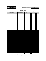
1
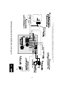
access control TECHNOLOGY
Operating & Installation Instructions
for ACTSmart
2 Product Range
ACTSmart2 Operating and Installation Manual
Rev. 1.0
Contents
Installation Notes ....................................................................................................4
Product Specification..............................................................................................4
30 Second Programming Guide..............................................................................5
Programming Summary......................................................................................... 6
ACTSmart Operation........... ..................................................................................7
ACTSmart Programming............ ............................................................................7
Adding a Card Batch ..............................................................................8
Deleting a Card Batch ............................................................................8
Adding a PIN ..........................................................................................8
Deleting a PIN ........................................................................................8
Adding a Card and PIN ..........................................................................8
Deleting a Card and PIN ........................................................................8
Adding a Card Batch using the keypad ..................................................9
Deleting a Card or Card and Pin using the keypad ................................9
Add Random Card ..................................................................................9
Set Door RelayTime......................................... ......................................9
Set Door Ajar Time.................................................................................9
Set Guest Buzzer Time................................... ........................................9
Change Programming Code..................................................................10
Change Number of PIN Digits ............................................................10
Set SmartLock Code ............................................................................10
Programming ACTSmart Options ........................................................................11
Setting Programmable Input Function................ .......................... .....12
Setting AUX I/O 1 Function ................................................................12
Setting AUX I/O 2 Function ................................................................12
I/O Function Code ................................................................................12
Quick I/O Setup ....................................................................................13
Adding a Card Batch for Second Door ................................................13
Adding a PIN for Second Door ............................................................13
Adding a Card and PIN for Second Door ............................................13
Add Random Card for Second Door ....................................................14
Programming a Network System..........................................................................15
Assign Door Numbers ..........................................................................15
Find Door Number................................................................................16
Find All Door Numbers ........................................................................16
Restoring Factory Default ....................................................................................16
Programming ACTSmart Prox only ....................................................................17
Adding a Card ......................................................................................17
Deleting a Card ....................................................................................17
Programming the Door Relay Time ....................................................17
Default ACTSmart ................................................................................17
ACTSmart Standalone Installation diagram ........................................................18
ACTSmart Interlock and Fire Override wiring diagram ......................................19
ACTSmart Network Installation diagram ............................................................20
ACTSmart Flush mounting diagram ....................................................................21
ACTSmart Surface mount diagram...... ................................................................22
User List ..............................................................................................................24
3
ACTSmart2 Operating and Installation Manual
Rev. 1.0
Installation Notes
• Remember to Factory Default the ACTSmart before programming
• Remember to place the supplied varistor across the terminals of the door strike coil to protect the relay
contacts
• Don’t mount the ACTSmart Prox units near RF sources (Eg mobile phones, radio transmitters,
computer monitors) or metal surfaces.
• Remember that the ACTSmart PIN and Prox units default to Card operation. Card and PIN
operation must be programmed in. (See Programming ACTSmart Options section, Options 39, 40 and
41).
• Don’t power the unit from a switch-mode power supply. Use a linear regulated power supply.
• Never use the on-board relay to switch AC mains voltage. An external relay, electrically isolated from
the ACTSmart should be used for this purpose
• Remember to change the programming code.
• Don’t power the ACTSmart from an AC power supply on a networked system. An AC power supply
may only be used on a standalone ACTSmart.
• The ACTSmart2 version is not compatible with the earlier version of ACTSmart. Cards and fobs for
one version will not work on the other. The devices may NOT be networked together.
Important
As with any Access Control system, always ensure there is an alternate means of escape in the event
of the unit failing to operate due to power loss or in the event of fire.
Product Specification
Number of Users
Supply Voltage
Current Consumption
Output Current Sink
Operating Temperature
Door Open Time
Max. ACTSmarts per network
Length of network
Relay Contact Rating
Programmable Inputs
Programmable Input/Outputs
Controller Size
Controller Weight
Water Resistance
Construction
1000
12 - 24 V DC (linear PSU) or AC (standalone only)
50mA (nominal), 80mA (maximum)
100mA
-10 to +50 degrees C
0 - 255 seconds
8
1.4km maximum
5A / 250Vac
1
2
Flush Mount: 100 x 110 x 20 mm
Surface Mount: 100 x 110 x 35 mm
200 grams
High IP67
Rugged Polycarbonate housing with stainless steel keys and
potted electronics.
Ordering Information
Model
Part Number
ACTSmart Proximity Only
ACT 1070
ACTSmart PIN and Proximity
ACT 1080
ACTSmart PIN Only
ACT 1090
4
ACTSmart2 Operating and Installation Manual
Rev. 1.0
30 Second Programming Guide
(For typical Standalone System)
1. Enter Programming Mode.
Press ✘ button followed by the programming code (default is 9999)
The LED will flash amber.
2. Add a Batch of Cards (ACT 1080 only)
Press 10, then present the first card in the batch followed by the last card in the batch.
Press ✔ button to complete.
3. Add a PIN Code
Press 12, and then enter a 4-digit PIN code.
Press ✔ button to complete.
(On ACT 1080 set Option 40 - Card or PIN.)
4. Set Desired Door Relay Active Time
Press 20, and then enter the desired number of seconds from 000-255 (three digits with
leading zeros). Press ✔ button to complete.
5. Change Programming code
Press 23, then enter new 4-digit programming code.
6. Exit Programming Mode
Press the ✘ button. The LED turns red.
The ACTSmart is now ready for normal use.
Note: The ACTSmart may be returned to its factory default condition at any time by entering the
programming mode and pressing 80 followed by the ✔ button.
For information on programming the advanced features and networking the ACTSmart range, please
refer to the complete programming guide.
access control TECHNOLOGY
Unit 8, Tallaght Business Centre,
Whitestown, Dublin 24, Ireland
Tel: 353-1-4622585 Fax: 353-1-4622587
Web: http://www.accesscontrol.ie
E-mail: [email protected]
Copyright © 2003 Access Control Technology Ltd.
5
ACTSmart2 Operating and Installation Manual
Rev. 1.0
Programming Summary
Code
Function
Default
10
11
12
13
14
15
16
17
18
Add Card Batch
Delete Card Batch
Add PIN Code
Delete PIN
Add Card and PIN
Delete Card and PIN
Add Card Batch using keypad
Delete Card Batch using keypad
Add Random Card
20
21
22
23
24
Set Door Relay Time
Set Door Ajar Time
Set Guest Buzzer Time
Change Programming Code
Change Number of PIN Digits
5 seconds
30 seconds
2 seconds
9999
4
30
31
32
33
34
35
36
37
38
39
40
41
Door Chime
Silent Operation
Lock-saver (Anti Tailgating)
Toggle
Door Forced Alarm
Door Ajar Alarm
Guest Button
Duress Codes
Network Master
Card and PIN
Card or PIN
Card and any PIN
Off
Off
Off
Off
On
On
On
Off
Off
Off
Off
Off
50
51
52
53
Set Programmable Input
Set AUX I/O 1
Set AUX I/O 2
Quick I/O Setup
Door Release Button
Door Contact
Door Alarm
60
61
62
Assign Door Numbers
Find Door Number
Find Door Numbers
70
71
72
73
Add Card Batch for Second Door
Add PIN code for Second Door
Add Card and PIN for Second Door
Add Random card for Second Door
80
Default Unit
6
ACTSmart2 Operating and Installation Manual
Rev. 1.0
ACTSmart Operation
The ACTSmart family consists of Proximity only, Pin and Proximity and PIN only units. Each
ACTSmart can operate in standalone mode. Up to 8 ACTSmart devices can be connected on a RS485
network. The ACTSmart will support a maximum of 1000 tokens. A token may be a card or a PIN code.
Each unit is contained in a rugged polycarbonate housing, with stainless steel keys and potted
electronics, allowing for indoor and outdoor installation.
Programming the unit is achieved via the keys and LED. For quick and easy installation, the
ACTSmart has a default configuration, which is suitable for most installations. Cards and PIN codes
can be programmed into the ACTSmart very quickly. ACT recommends that the user keep track of the
Cardholders and PIN users on the system by using the User List at the end of the manual. Make copies
of this sheet and enter each Users details on it. This will allow users to be deleted later on, even if a card
is lost or a user forgets their PIN code.
To improve security, PIN codes may be up to 6 digits in length. Normally only card users are allowed
access through the ACTSmart PIN and Prox unit. For maximum security, the unit may be programmed
to require all users to enter a PIN code after presenting a card. For lower security applications, another
programming option allows access to PIN only users. A duress code feature is also available
The built-in inputs and outputs are programmable, allowing the ACTSmart to be used in a wide variety
of applications from simple door access, to cash offices and fire exits. Each unit also has built-in tamper
monitoring for improved security.
ACT also provide an easy-to-use PC application (ACTWinSmart), which allows the installer to configure
systems quickly. Up to 8 ACTSmart units may be connected to the PC. The end-user may also use
ACTWinSmart to monitor day-to-day activity, add new users etc.
ACTSmart Programming
Press the ✘ button followed by the programming code (initially 9999). The LED will flash amber
while in programming mode. If ✘ is pressed at any time or no key is pressed within 30 seconds,
programming mode is exited. If the LED flashes green during programming, then a card presentation
is expected. If the LED flashes red, then a keypress is expected. While the ACTSmart is busy
performing a task, (Eg. Defaulting memory, adding cards), the green led will turn on and the buzzer
will sound an elongated tone.
Note: In most Programming Menus there is a step that is marked (optional)*. This setting only applies
to a Networked System (see Programming a Network System).
7
ACTSmart2 Operating and Installation Manual
Rev. 1.0
Adding a Card Batch:
Step
1
2
3
4
5
Keypad Entry
Operation
10
Present Card
Present Card
Enter 1-8, (optional)*
Press ✔
Add Card Batch
First card in Batch (lowest number card)
Last Card in Batch (highest number card)
Select each door this batch enabled for
End programming card batch Note: the buzzer will sound while cards are loaded into memory.
Deleting a Card Batch:
Step
1
2
3
4
5
Keypad Entry
Operation
11
Present Card
Present Card
Enter 1-8, (optional)*
Press ✔
Delete Card Batch
First card in Batch (lowest number card)
Last Card in Batch (highest number card)
Select each door this batch deleted from
End delete card batch Note: the buzzer will sound while cards are deleted from memory.
Adding a PIN:
Step
Keypad Entry
Operation
1
2
3
4
12
0001-9999
1-8, (optional)*
Press ✔
Add PINs
(Make sure Option 40 is set on PIN and Prox units.)
4 - 6 digit PIN code
Select each door this PIN is valid for
End programming PINs
Deleting a PIN:
Step
Keypad Entry
Operation
1
2
3
4
13
0001-9999
1-8, (optional)*
Press ✔
Delete PINs
4 - 6 digit PIN code
Select each door this PIN is deleted from
End deleting PINs
Adding a Card and PIN:
Step
Keypad Entry
Operation
1
2
3
4
5
14
Present Card
0001-9999
1-8 (optional)*
Press ✔
Add Card and PIN
(Make sure Option 39 is set on PIN and Prox units.)
4 - 6 digit PIN code
Select each door this Card & PIN is valid for
End programming Card and PINs
Deleting a Card and PIN:
Step
Keypad Entry
Operation
1
2
3
4
15
Present Card
1-8, (optional)*
Press ✔
Delete Card and PIN
Select each door this Card & PIN is deleted from
End deleting Card and PINs
8
ACTSmart2 Operating and Installation Manual
Rev. 1.0
Adding a Card Batch using the keypad:
Step
1
2
3
4
5
Keypad Entry
16
Enter 10-digit card
number
Enter 10-digit card number
1-8, (optional)*
Press ✔
Operation
Add Card Batch
10-digit First Card number with leading zeros.
Eg. Card 54321 enter 0000054321.
Second Card number
Select each door to which these cards are enabled
End Adding Card Batch — Note: the buzzer will sound while cards are
loaded into memory.
Deleting a Card or Card and PIN using the keypad:
Step
1
2
3
4
Keypad Entry
17
Enter 10-digit card number
1-8, (optional)*
Press ✔
Operation
Delete Card or Card and PIN
10-digit Card number with leading zeros.
Eg. Card 54321 enter 0000054321.
Select each door this Card is deleted from
End deleting Card (Card and PIN)
Add Random Card:
Step
1
2
3
4
5
6
Keypad Entry
18
Enter 1-8, (optional)*
Press ✔
Present Card
Present Card (optional)*
Press ✔
Operation
Add random card
Select each door these cards enabled for
Add card
Repeat for all other cards to be added
End adding cards
Set Door Relay Time:
Step
1
2
3
4
Keypad Entry
Operation
20
Enter 3 digit time
1-8 (optional)*
Press ✔
Set Door Relay Time - (default 5 seconds)
000-255 seconds - (leading zeros required).
Select each door this timer is set for
End setting Door Relay Timer
Set Door Ajar Time:
Step
1
2
3
4
Keypad Entry
Operation
21
Enter 3 digit time
1-8 (optional)*
Press ✔
Set Door Ajar Time - (default 30 seconds)
000-255 seconds - (leading zeros required).
Select each door this timer is set for
End setting Door Ajar Time
Set Guest Buzzer Time:
Step
1
2
3
4
Keypad Entry
Operation
22
Enter 3 digit time
1-8 (optional)*
Press ✔
Set Guest Buzzer Time - (default 2 seconds)
000-255 seconds - (leading zeros required).
Select each door this timer is set for
End setting Guest Buzzer Time
9
ACTSmart2 Operating and Installation Manual
Rev. 1.0
Change Programming Code:
Step
1
2
Keypad Entry
Operation
23
0001-9999
Change Programming code
New 4 - 6 digit programming code
Change Number of PIN Digits:
Step
1
2
Keypad Entry
Operation
24
4-6
Change Number of PIN digits
Select number of PIN digits in range 4 to 6. When set, the codes require
leading zeros Eg. Code 9999 becomes 009999 for 6 digits.
Set SmartLock Code:
Step
Keypad Entry
Operation
1
2
3
4
25
0001-9999
1-8 (optional)*
Press ✔
Set SmartLock code
New 4 - 6 digit SmartLock code
Select each door this code is set for
End setting SmartLock code
10
ACTSmart2 Operating and Installation Manual
Rev. 1.0
Programming ACTSmart Options:
Step
1
2
3
4
Keypad Entry
30-41
0 or 1
1-8, (optional)*
Press ✔
Operation
Select Option Number
0 = Off, 1 = On
Select each door this option is set for
End setting options
Option
Function
Default
Operation
30
Door Chime
Off
When set, whenever the door contact is opened, the built-in buzzer
makes a chime sound and the buzzer output activates for 2 seconds
31
Silent Operation
Off
When set, the keypad operates silently, that is no audible tones
(key-presses or confirm tones) are produced from the built-in
buzzer
32
Lock-saver
(Anti Tailgating)
Off
When set, and when the door relay is active (following a valid code
or button release), the door relay timer is truncated to 2 seconds
when the door contact opens. This ensures that irrespective of
programmed relay time, the door will be locked as soon as it
closes, and any person following will have to enter a code.
33
Toggle
Off
When set, the door relay toggles for each valid entry. The green
LED flashes when the door is toggled open.
34
Door Forced Alarm
On
When set, the buzzer output / door alarm output is activated if the
door contact opens when the door is locked. The output is
deactivated when a valid card or PIN is next entered. This is useful
for monitoring fire doors etc.
35
Door Ajar Alarm
On
When set, and the door contact has been open for longer than the
time programmed into the door ajar timer, the buzzer output / door
alarm output is activated. Closing the door and presenting a valid
card or entering a valid PIN deactivates the output.
36
Guest Button
On
When set, (default) and when the ✔ key on the keypad is pressed,
the buzzer output is activated for the duration programmed in the
guest buzzer timer.
37
Duress Codes
Off
When set, and when a duress PIN is entered, the door is opened
normally and the Door Alarm output activated. A duress PIN is
any valid PIN with one added to the last digit. The output will be
reset when a valid user enters. When the duress option is set,
avoid using PINs that are different by 1.
38
Network Master
Off
Set one device on the network to be the Master.
39
Card and PIN
Off
When set, only Card and PIN users are admitted. This is only valid
for ACTSmart PIN and Prox units.
40
Card or PIN
Off
When set, either a valid Card or valid PIN will open the door. This
is only valid for ACTSmart PIN and Prox units.
41
Card and any PIN
Off
In this mode, a valid card and any valid PIN code will open the
door. This is only valid for ACTSmart PIN and Prox units. This
mode allows all users to have a common PIN code to use with their
cards.
11
ACTSmart2 Operating and Installation Manual
Rev. 1.0
Setting Programmable Input Function:
Step
1
2
3
4
Keypad Entry
50
0-6
1-8 (optional)*
Press ✔
Operation
Set Input Function (Door Release button is default)
Select I/O Function Code (see below for explanation of codes)
Select each door this function is valid for
End programming Input Function
Setting AUX I/O 1 Function:
Step
1
2
3
4
Keypad Entry
51
00-12
1-8 (optional)*
Press ✔
Operation
Set AUX I/O 1 Function (Door Contact is default)
Select 2-digit I/O Function Code (see below)
Select each door this function is valid for
End programming AUX I/O 1
Setting AUX I/O 2 Function:
Step
1
2
3
4
Keypad Entry
52
00-12
1-8 (optional)*
Press ✔
Operation
Set AUX I/O 2 Function (Door Alarm is default)
Select 2-digit I/O Function Code (see below)
Select each door this function is valid for
End programming AUX I/O 2
I/O Function Codes:
Code
0
1
Function
Door Contact
Operation
Input required if you wish to monitor Door Forced or Door Ajar
Fire Alarm Override
When this input is high, the door is opened and the green LED flashes (See
Fire Alarm Override Connections diagram). If this is wired into the Master
Smart, then all doors on the network will open.
2
Lock Door
When this input is low, the door locks and the red LED flashes.
3
Card and PIN
When this input is low, then only users who enter both Card and PIN will be
admitted. This option is only valid on an ACTSmart PIN and Prox.
4
Card or PIN
When this input is low, a valid Card or a valid PIN will open the door. This
option is only valid on an ACTSmart PIN and Prox.
5
Door Release Button
When this input is low, the door opens.
6
Second Door Release
Button
When this input is low, any I/Os configured as Second Door Lock will open
for the Door Lock Time.
7
Interlock
This normally behaves as an input and locks the door while the input is low.
While the door relay is active or the Door Contact is open, it becomes an
active output. (See Interlock Connections diagram).
8
Door Alarm
This output activates while an alarm is present - A door alarm may be a door
forced, door ajar, tamper or duress.
9
Follow
This output follows the state of the door relay.
10
Buzzer
This output activates for Door Chime or Door Alarms.
11
SmartLock
This output controls a SmartLock device for Secure doors.
12
Second Door Lock
This output will activate for the Door Lock Time when a valid card or PIN is
presented. See commands 70-73.
12
ACTSmart2 Operating and Installation Manual
Rev. 1.0
Quick IO Setup:
Step
Keypad Entry
Operation
1
53
Set Input Output Functions (0 - is default)
2
0-9
0
1
Select a code
Prog Input
Door Release Button
Door Release Button
AUX IO 1
Door Contact
Door Contact
2
Door Release Button
Door Contact
Interlock
3
4
Door Release Button
Door Release Button
Door Contact
Fire Override
SmartLock
Interlock
5
Door Contact
Follow
Door Alarm
6
7
8
9
Door Contact
Follow
Door Contact
Door Alarm
Fire Override
Interlock
Card And PIN
Interlock
Select each door this function is valid for
End Quick IO setup
3
4
1-8 (optional)*
Press ✔
AUX IO 2
Door Alarm
Buzzer
Buzzer
Buzzer
Buzzer
Follow
Adding a Card Batch for Second Door:
Step
1
2
3
4
5
Keypad Entry
70
Present Card
Present Card
Enter 1-8, (optional)*
Press ✔
Operation
Add Card Batch for Second Door
(I/O function code 12 must be set for the Aux O/P)
First card in Batch (lowest number card)
Last Card in Batch (highest number card)
Select each door this batch enabled for
End programming card batch.
Note: the buzzer will sound while cards are loaded into memory.
Adding a PIN for Second Door:
Step
1
Keypad Entry
71
Operation
Add PINs
2
3
4
0001-9999
1-8, (optional)*
Press ✔
4 - 6 digit PIN code
Select each door this PIN is valid for
End programming PINs
(Make sure Option 40 is set on PIN and Prox units.)
(I/O function code 12 must be set for the Aux O/P)
Adding a Card and PIN for Second Door:
Step
1
Keypad Entry
72
Operation
Add Card and PIN
2
3
4
5
Present Card
0001-9999
1-8, (optional)*
Press ✔
4 - 6 digit PIN code
Select each door this Card & PIN is valid for
End programming Card and PINs
(Make sure Option 39 is set on PIN and Prox units.)
(I/O function code 12 must be set for the Aux O/P)
13
ACTSmart2 Operating and Installation Manual
Rev. 1.0
Add Random Card for Second Door:
Step
1
2
3
4
5
6
Keypad Entry
73
Enter 1-8, (optional)*
Press ✔
Present Card
Present Card (optional)*
Press ✔
Operation
Add random card for Second Door
(I/O function code 12 must be set for the Aux O/P)
Select each door these cards enabled for
Add card
Repeat for all other cards to be added
End adding cards
14
ACTSmart2 Operating and Installation Manual
Rev. 1.0
Programming a Network System
Up to 8 ACTSmart devices can be connected on the network. See the ACTSmart Network Installation
diagram to complete the necessary connections.
Programming Door Numbers
To allow some users through a door and prevent access to other users, each ACTSmart on the network
must be given a door number (1-8). An ACTSmart Proximity Only Unit requires a door number if it is
to be programmed with advanced options.
Set a Master
Set one device on the network to be the Master. This device will be used for programming the entire
network and should be a PIN and Prox unit. The Master is automatically assigned door number 1. The
other ACTSmarts on the network (door numbers 2-8) are referred to as Slave Units. No programming is
allowed on a Slave (except to default it - see Restoring Factory Defaults).
Enter programming mode. Press buttons 3,8 followed by 1 to set the device to be the Master. The rest of
the units on the network are assigned door numbers by following the procedure below:
Assign Door Numbers:
Step
1
Keypad Entry
60
2
3
Any ACTSmart units without a door number start to beep. The
number of beeps is determined by the door number to be
programmed. Eg. If door 5 is to be programmed, all unassigned
ACTSmarts will beep 5 times.
Present card or press
key on Slave
4
5
Operation
Assign Door Numbers
This operation should take place on the desired door number. The
ACTSmart stops beeping.
Repeat step 2 until all ACTSmarts have been assigned a door number.
Press ✔ on Master
End programming door numbers
Assigning Users to Doors
When each ACTSmart has been given a unique door number, then users may be given access through
specific doors. In most programming menus, there is an optional step to program specific doors. For
example, when programming a Card Batch, the user may select which doors the Card Batch applies to
(Step 4 in Adding Card Batch, see above). Skip this optional step if programming is to apply to all doors
on the network.
Checking Network Programming
The door number of any ACTSmart on the network can be found using the menus below. This is a useful
check to perform to verify communications from the Master to the Slave units and to check that the Door
Numbers have been assigned correctly.
15
ACTSmart2 Operating and Installation Manual
Rev. 1.0
Find Door Number:
Step Keypad Entry
1 61
2 1-8
3
Press a key or present
a card
Operation
Find Door Numbers
Enter the door number to be found. The ACTSmart assigned the door
number starts to beep.
To stop the ACTSmart beeping.
Find All Door Numbers:
Step
1
2
3
Keypad Entry
62
Operation
Find Door Numbers
Press ✔
Press key or present card
at each ACTSmart
Each ACTSmart beeps their door number
To stop the ACTSmart Beeping
Adding a Slave to the Network
Another Slave can be added to the network by defaulting it first (see below) and then assigning it a
door number from the Master.
Removing a Slave from the Network
To remove a Slave unit from the network, simply disconnect it from the network.
Replacing a Slave Unit
To replace a Slave Unit, remove the old Slave from the network. Default the new Slave and add it to
the network. Assign a door number to it from the Master.
Replacing the Master Unit
If the Master Unit needs to be replaced, then replace it with a Slave unit already on the system, (as
it will have all the card/PIN information), and make it the Master. Add a new, defaulted Slave to the
network in place of the swapped-out Slave. Then assign a Door number to the new Slave - make sure
it is the Door number of the old Slave.
Restoring Factory Defaults
Enter Programming code followed by 80 followed by ✔. If this is done on the Master ACTSmart then
all ACTSmarts on the network are defaulted (including the Master). If it is done on a Slave then only
the Slave is defaulted.
If the programming code has been forgotten, power up with the tamper open (by removing the main
unit from the mounting plate or the surface mount collar), while holding down the ✘ key. Release the
✘ key and then enter the default Programming Code (9999).
Defaulting memory takes 3-4 seconds. During this time, the buzzer will sound an elongated tone.
16
ACTSmart2 Operating and Installation Manual
Rev. 1.0
Programming ACTSmart Prox Only
To program an ACTSmart Prox Only device, a Programming Card must be assigned to the ACTSmart.
The Programming Card may be any proximity card. To set the Programming Card into the ACTSmart
Prox, power up the device with the tamper open (by removing the main unit from the mounting plate or
the surface mount collar), and immediately present a card twice. (Note: ACT recommends using an
ACTSmart PIN and Prox device if a network is required).
Adding a Card:
Step
1
2
3
Present
Operation
Programming Card
Present new Card
Add Card
Card added to the Prox only
If more cards to be added, repeat from Step 1
Deleting a Card:
Step
1
2
3
4
Present
Operation
Programming Card
Programming Card
Delete Card
Present Card to be deleted Card deleted from Prox only
If more cards to be deleted, repeat from Step 1
Programming the Door Relay Time:
Step
1
2
3
Present
Programming Card
Programming Card
Programming Card
4
Programming Card
Operation
Wait for 4 seconds, Buzzer sounds indicating timing... wait
required period.
Buzzer stops - timer set.
Default ACTSmart:
Step
Present
1
2
3
4
Programming Card
Programming Card
Programming Card
Programming Card
5
Present Card
(Not Programming Card)
Operation
Buzzer sounds intermittently and the LED flashes RED to warn
you are about to default the system
Default ACTSmarts. Note: This deletes the Programming Card.
17
18
Access Control Technology, Unit 8, Tallaght Business Park, Whitestown, Dublin 24, Ireland.
Tel: 353-1-4622585 Fax: 353-1-4622587 Web: http://www.accesscontrol.ie E-mail: [email protected]
ACTSmart Standalone Installation Diagram
19
Access Control Technology, Unit 8, Tallaght Business Park, Whitestown, Dublin 24, Ireland.
Tel: 353-1-4622585 Fax: 353-1-4622587 Web: http://www.accesscontrol.ie E-mail: [email protected]
ACTSmart Interlock Connections
ACTSmart Fire Alarm Override Connections
20
SHIELD
SHIELDS
DC Power
Supply Unit
SHIELD
Continue daisy chain to
remaining ACTSmart units
on the network (maximum 8).
Access Control Technology, Unit 8, Tallaght Business Park, Whitestown, Dublin 24, Ireland.
Tel: 353-1-4622585 Fax: 353-1-4622587 Web: http://www.accesscontrol.ie E-mail: [email protected]
Do NOT use AC Power Supply.
MUST be 12V or 24V DC.
DC Power
Supply Unit
Total cable length
maximum 1.4km
Network cable is single shielded twisted pair, Belden 9501 or similar.
Note:
When networking the ACTSmart units,
common the 0V of each ACTSmart to avoid
ground loop issues.
ACTSmart Network Installation Diagram
21
SCREWS
Place the Reader / Keypad onto the surface mount
collar and clip down into place. Use the security screw
supplied to attach the unit to the surface mount collar.
Place the cap onto the unit
and push firmly into place.
Security screw supplied with the unit.
Access Control Technology, Unit 8, Tallaght Business Park, Whitestown, Dublin 24, Ireland.
Tel: 353-1-4622585 Fax: 353-1-4622587 Web: http://www.accesscontrol.ie E-mail: [email protected]
ENSURE the correct spacers have been used to
bridge the gap between the mounting plate and
the fixing wings of the pattress box to avoid the
mounting plate being distorted.
Mounting plate is attached to the pattress box
using the screws supplied.
Magnet in mounting plate,
which keeps tamper switch
closed inside ACTSmart.
View showing
spacers stacking.
Note:
Determine the distance between the pattress box
and the mounting plate, using the spacers which are
labelled 1mm to 4mm. This allows the installer to
make the required spacer length 1 to 10mm by
stacking each spacer together.
View showing mounting plate
before spacers are broken.
Spacers break away
from main component
when required by
installer for use.
ACTSmart Mounting Instructions for Flush-Mount Unit
22
Place the Reader / Keypad onto the surface mount collar and clip down
into place. Use the security screw supplied to attach the unit to the
surface mount collar.
Place the cap onto the unit
and push firmly into place.
Security screw supplied with the unit.
Access Control Technology, Unit 8, Tallaght Business Park, Whitestown, Dublin 24, Ireland.
Tel: 353-1-4622585 Fax: 353-1-4622587 Web: http://www.accesscontrol.ie E-mail: [email protected]
The surface mount collar is mounted on the
wall using the fixing kit supplied in the box.
Magnet in surface mount collar, which keeps
tamper switch closed inside ACTSmart.
ACTSmart Mounting Instructions for Surface Mount Unit
ACTSmart2 Operating and Installation Manual
Rev. 1.0
NOTES
23
Smart
access control TECHNOLOGY
User List
User Name
Card Number
PIN
Doors
1
2
3
4
5
6
7
8
Access Control Technology, Unit 8, IDA Business Park, Whitestown, Dublin 24, Ireland.
TEL:353-1-4622585 FAX: 353-1-4622587 WEB: http://www.accesscontrol.ie E-MAIL: sales@ accesscontrol.ie