1
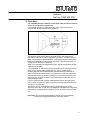
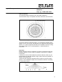
Light-Management
Standard presence
detector
Ref.-no. PMS 360 WW
Operating Instructions
Standard presence detector
1. Presence detector basics
Like a movement detector or an alarm system detector, the standard
presence detector , too, belongs to the family of PIR detectors.
At first glance, all three types are equivalent. Due to their different internal
design and different signal detection and treatment procedures, these
types are suitable for different applications:
•
Depending on brightness, a movement detector switches the light on
when movement is detected. It switches the light off independent of
brightness when no movement is detected anymore, at the latest,
however, after 90 minutes (forced shutoff).
•
An alarm system detector reports detected movements independent of
brightness to an alarm center. The number of pulses generated within
a fixed time span is often adjustable.
•
A presence detector is designed to switch on the light depending on
brightness when presence is detected and then to switch it off again
when it is no longer needed, i.e. when it is already too bright or when
there is no one in the room anymore.
What the detector does therefore is to detect the presence of persons
depending on a preset brightness.
The differences between these PIR detectors lie essentially in the design
of the Fresnel lense, the adaptation to ambient conditions, the type of
fitting and the type of movement or brightness signal transmitted.
Stand: Dez-08 82534303
Light-Management
Standard presence
detector
Ref.-no. PMS 360 WW
2. Function
The standard presence detector is therefore used to monitor internal
rooms for the presence of persons.
It is installed exclusively under the ceiling of the room from where it
monitors the working surface below (figure A).
A
The detector works with a passive infrared sensor (PIR sensor) and
responds to thermal movement triggered by persons, animals or objects.
When movements are detected below a presettable brightness threshold,
the detector switches on an electrical consumer. The device remains on
as long as movements are detected.
When no movements are detected anymore, the device switches off after
a preset shut-off delay.
If the brightness on the surface under supervision is permanently at least
twice as high as the preset brightness (e.g. due to supplementary
daylight), the test LED flashes and the presence detector switches off
after 10 minutes at the latest even if movements are still being detected.
The standard presence detector is designed for switching purposes only
and is used in combination with a Light- Management insert (for 60 mm
flushmounting boxes).
It can be combined with all Light- Management inserts. Dimmer inserts
can be used as switching inserts. The insert must be selected depending
on load to be connected.
The device can be used together with a Light-Management „3-wire“
extension unit insert. In this case, the detection and treatment of signals is
independent of brightness (see chapter “Use of extension units” on page
37).
Important: The load rating specifications are set out in the operating
instructions of the individual flush-mounting inserts.
2
Light-Management
Standard presence
detector
Ref.-no. PMS 360 WW
3. Safety instructions
Attention: Electrical equipment must be installed and fitted by
qualified electricians only.
The device is not suitable for safety disconnection.
Depending on the type of flush-mounting insert used, the
deactivation of the device does not isolate the load electrically from
the power mains. When working on the load or on the device, the
device must be safely disconnected from the power mains
Non-observation of the installation instructions may cause fire or
other hazards.
Installation
The standard presence detector is installed exclusively under the ceiling.
Select a flush-mounting insert in accordance with the load to be used,
install in the ceiling and connect to the power supply and/or load (see
connection diagrams, page 48).
Plug the presence detector standard into the insert without exerting
pressure on the lens. The electrical contact is established through the
connector pins.
Sources of interference:
Do not install in the direct vicinity of heat sources such as lamps (figure
B). The cooling lamp may be interpreted by the PIR sensors as a thermal
change and lead to repeated switching. If necessary, restrict the detection
field with the supplied snap-on mask (see chapter “Snap-on mask” on
page 19). Do not install close to fans, radiators or ventilation ducts.
Moving air (e.g. draught through open windows) might be detected and
lead to repeated switching. Select the best suited place for the installation.
B
The field of detection should not be restricted by furniture, columns,
etc.
Avoid direct sunlight into the sensor window.
The sensors can be irreparably damaged by the high thermal energy.
3
Light-Management
Standard presence
detector
Ref.-no. PMS 360 WW
The brightness sensor should be installed away from windows to avoid
the undesirable influence of scattered light. Install the presence detector
standard free from vibrations to avoid switching triggered by sensor
movements
Adjustments (figure C)
To adjust the brightness or the shut-off delay, withdraw the trimming ring
from the presence detector standard. The controls are then accessible.
c Shut-off delay: 1 second (test operation). The time potentiometer
permits adjusting the time intervals in fine steps between ca. 10 seconds
and 30 minutes.
d Brightness: adjustable between 10 lux (moon symbol) and 1000 lux
(sun symbol) and manual setting “0”.
C
Important: In the “0” setting, the presence detector standard can
only be switched on from an extension unit.
The shut-off brightness in this case is approximately 400 lux. This setting
permits to deactivate the automatic detection mode. Typical application:
orientation lighting in residential rooms.
Snap trimming ring back onto the detector after the adjustment. The nose
of the brightness sensor must engage in the corresponding notch in
trimming ring (3).
The test LED (4) is useful for diagnosis and adjustment (see chapter “Test
LED functions” on page 27) and is visible only after removal of the
trimming ring.
4
Light-Management
Standard presence
detector
Ref.-no. PMS 360 WW
Installation and test mode
•
Install the insert.
•
Connect the lamps (e.g. workplace illumination) and the power supply
•
Snap the presence detector onto the insert.
•
Set the time potentiometer to the shortest interval (test 1 sec.) (see
figure D).
•
Set the lux potentiometer to daytime operation (sun symbol) (see
figure D).
•
Switch on the power supply.
D
The lamps connected are switched on by the presence detector for a
measuring cycle of abt. 1 minute. During the measuring cycle no
operation is possible. After this time, the device switches off and is then in
the test mode.
Each movement now detected switches on the device for at least 1
second (with retriggering function ). A walking test to check the field of
detection can now be performed. If necessary, the snap-on mask must be
used (see chapter “Snap-on mask” on page 19).
5
Light-Management
Standard presence
detector
Ref.-no. PMS 360 WW
Snap-on mask
The snap-on mask supplied with the detector can be used to blank out
undesired zones or sources of interference (see chapter “Installation sources of interference on pages 11 – 13) by restricting the detection
range of the device.
Important: The device is delivered with the transparent snap-on mask for
protection of the lens system. Remove the mask to obtain the
maximum field of detection.
E
The mask is snap-fitted on the lens system (figure E).
The removed mask is cut out with scissors along the marked lines (figure
F).
F
Bereiche I bis III
Cutting out the mask changes the diameter of the detection field on the
floor as follows:
Sectors I through III see figure F.
cut-outs, sector I:
∅ approx. 2.20 m
Sector II cut out:
∅ approx. 4.00 m
Sectors II and III cut out: ∅ approx. 6.00 m
Without mask:
∅ approx. 8.00 m
The figures are based on a fitting height of approx. 2.50 m.
Adaptation of sensor to the lighting conditions of the monitored
surface
To prevent the presence detector from being switched out again by the
lamp it has just activated (brightness exceeded), the detector must be
adjusted to the actual lighting conditions.
6
Light-Management
Standard presence
detector
Ref.-no. PMS 360 WW
The adjustment must therefore be made under those lighting conditions
that are required for minimum brightness at the place of work, i.e. lamps
switched on with as little scattered light as possible.
Procedure:
•
Set the time potentiometer to maximum interval (30 minutes) (figure
G).
•
Set the lux potentiometer to daytime operation (sun) (figure G), the
LED must be off.
•
Activate the device by making a movement inside the field of
detection.
G
Some lamps such as fluorescent lamps, for instance, need a certain time
to reach full brightness.
Therefore:
•
Observe the starting time of the lamps.
Important: Avoid scattered light (e.g. from additional daylight or from
nearby lamps).
•
Then, turn the lux potentiometer in the direction of the moon symbol
(figure G) until the test LED (4) (figure H) lights up.
Important: Do not shade the light sensor (5) (figure H) during this
adjustment. The sensor must be able to measure the light reflected from
the full monitored surface.
The standard presence detector is then adjusted to the actual brightness
prevailing at the monitored surface.
7
Light-Management
Standard presence
detector
Ref.-no. PMS 360 WW
•
Set the time potentiometer to the desired shut-off delay.
•
Leave the field of detection and wait until the presence detector
switches off after the time interval just set.
Important: If the first setting is not fully satisfactory, please observe the
instructions in the chapters: “Standard setting”, “Test LED
function” and “Setting guidelines” on pages 25 – 35.
Standard setting
If it is not possible to simulate the desired lighting conditions with the
means available (room has no darkening facility), a standard setting can
be selected. For this setting, the lux potentiometer must be adjusted as
shown in figure I.
I
Any readjustments can be made with the help of the test LED and the
setting guidelines (see pages 27 - 35).
There is no response to movements inside the field of detection when the
preset brightness (load switched off) is exceeded by additional light such
as daylight or light from nearby lamps. In this case, the test LED is lit up or
flashes and the lighting remains off.
Functions of the test LED
When the first attempt to adjust the brightness was not satisfactory, the
setting can be verified and the brightness be readjusted with the help of
the test LED and the setting guidelines (page 31 -35).
States of the test LED and their meaning (load disconnected):
LED OFF
Æ monitored surface too dark: load switched on after detection of
movements.
LED ON or LED flashing:
Æ monitored surface bright enough: load remains off even after detection
of movements
States of the test LED and their meaning (load connected):
LED OFF
Æ monitored surface too dark:
The load remains on after detection of movement and the retriggering
function is active. If no movement is detected, the device switches off after
the preset shut-off delay.
LED ON
Æ monitored surface sufficiently illuminated by the activated lights:.
The load remains on after detection of movement and the retriggering
function is active. If no movement is detected, the device switches off
after the preset shut-off delay.
8
Light-Management
Standard presence
detector
Ref.-no. PMS 360 WW
LED flashing
Æ monitored surface very bright due to the light from burning lamps and
external light:
The load is switched off after 10 minutes at the latest with or without
detection of movements, since the brightness at the working surface
even without lighting is higher than the preset brightness.
Important:In the first seconds after shutoff, this brightness may seem to
be insufficient.
Einstellhilfe
Load remains on even at high levels of external light.
Cause:
Preset brightness value too high
Remedy: Turn lux potentiometer towards moon symbol.
Load is not activated despite insufficient brightness and movement
detection.
Cause 1:
Preset brightness value too low
Remedy: Turn lux potentiometer towards sun symbol.
Cause 2:
Device deactivated from extension unit (e.g. pushbutton).
Remedy:
Re-activate from extension unit.
Cause 3:
Remedy:
Device set to “0” (chapter “Settings” on page 15).
Re-activate from extension unit.
Load switches off in spite of the presence of persons and
insufficient lighting levels.
Cause:
Preset shut-off delay too short.
Remedy: Prolong delay with time potentiometer.
Cause:
Remedy:
Detection problem: surface to be monitored not completely in
the detector’s field of view. View obstructed by furniture or
columns.
If needed, use another presence detector extension unit to
enlarge the field of detection (see chapter “Use of extension
units” on page 37).
Load switched on without any noticeable movement detected.
Cause:
Sources of disturbance in the field of detection
Remedy: see chapter “Installation” on page 11
Load switches off briefly and then on again
Cause:
After shut-off, the ambient brightness falls below the preset
minimum brightness level so that the device switches on again
immediately when movement is detected.
Remedy: Increase the shut-off threshold by turning the lux
potentiometer a little bit towards the sun symbol.
9
Light-Management
Standard presence
detector
Ref.-no. PMS 360 WW
Tip: With fewer movements expected in the monitored area, the shut-off
delay should be selected longer to prevent premature switching off
of the lights.
Use of extension units
The standard presence detector on a Light-Management “3-wire“
extension unit insert for presence detectors enlarges the detection field of
the main unit.
Important:
• The extension unit is not suitable for direct switching of loads
and merely transmits movement detection signals independent of
brightness to the main unit.
•
The standard presence detector cannot be used on an extension
unit insert designed for two-wire operation.
If the main unit and the extension unit are each equipped with a standard
presence detector, switching is performed dependent on the brightness
value detected by the main unit. When used in this configuration, the
setting controls of the attachment on the extension unit are not
operational. The adjustment is performed only at the main unit. When the
standard presence detector is used in combination with the LightManagement “3-wire“ extension unit insert, the detection system is locked
for about 3 seconds after the lights have been shut off before they can be
switched on again from the extension unit.
Activation through extension input 1 of the insert:
If a flush-mounting insert with extension input 1 (e.g. relay insert) is used
under the main presence detector and switched off through extension
input 1, the reactivation, within the next 2 minutes is then only possible
through extension input 1.
Movements detected by the PIR sensors during this interval will not
reactivate the device. If movements are detected within this 2-minute
interval, the main unit will be locked again for another 2 minutes.
The automatic mode of the main unit will be reactivated only if the 2minute interval has elapsed without movements being detected. In this
case, all movements detected will again lead to switching on of the lamps
depending on prevailing brightness conditions.
This feature offers the possibility of deactivating the automatic mode on
pur-pose if, for instance, a room is to be darkened.
The lighting can be switched on via extension input 1 independent of
brightness. The brightness evaluation remains active. This means that the
lighting is switched off after 10 minutes if is not needed.
10
Light-Management
Standard presence
detector
Ref.-no. PMS 360 WW
Field of detection
The standard presence detector has a 360° field of detection.
The PIR sensor array is composed of 6 levels of detection and 80 lenses.
J
View from above: figure J
The field of detection measures approx. 5 m in diameter at desktop level
(approx. 80 cm). On the floor, the diameter of the detection field measures
approx. 8 m. These ranges are referred to an installation under the ceiling
and a fitting height of 2.5 m and tangential, i.e. lateral direction of
movement.
Important:
Range reductions must be expected if movement is directed towards the
presence detector. In such a case, a detection in the outer 4 m range is
not granted.
If a person moves too fast towards the presence detector, there may be
the impression of reduced detection range. Observe also the possible ondelays of the lamps used.
These facts are especially important when the device is used as ceiling
detector. If the installation heights are increased the detector’s sensitivity
to movements is lower.
K
Sideview: figure K
11
Light-Management
Standard presence
detector
Ref.-no. PMS 360 WW
4. Technical data
Angle of detection 360°
Nominal field of detection
at desktop level:
∅ approx. 5 m
Nominal field of detection
at floor level:
approx. 8 m
Height of installation for
nominal field of detection: approx. 2,5 m
The nominal field of detection varies with the height of installation.
Number of lenses /levels of detection:80 / 6
Nominal voltage:
AC 230 V~; 50 Hz
Switching capacity:see insert instructions
Shut-off delay: 1 sec. in test mode, approx. 10 sec. - 30 min.
Brightness:
approx. 10 – 1000 lux
Number of extensions connected to flushmounting insert:
passive (e.g. pushbuttons): unlimited
active :
see instructions for
3-wire“extension
nit insert
Length of extension unit
connection cable:
00 m max.
Technical specifications subject to change.
Application of inserts
The standard presence detector can be used exclusively for switching
applications. The detector is used in combination with the inserts of the
Light-Management series. Dimmerinserts can be used as switching
inserts:
- universal touch dimmer Art.-Nr. 1254 UDE (figure L)
- standard touch dimmer Art.-Nr. 1225 SDE (figure L)
- relay insert Art.-Nr. 1201 URE (figure M)
- Tronic switching insert Art.-Nr. 1254 TE (figure N)
- Triac switching insert Art.-Nr. 1244 TE (figure N)
- 2-channel relay insert Art.-Nr. 1202 URE (figure O)
- Pushbutton control unit Art.-Nr. 1240 STE (figure P)
- “3-wire“extension unit insert Art.-Nr. 1223 NE (figure Q)
Important: Parallel connection of presence detector main units is not
allowed.
The device cannot be used in combination with the 2-wire extension unit
insert as active extension unit.
12
Light-Management
Standard presence
detector
Ref.-no. PMS 360 WW
The 2-wire extension unit insert can, however, be used in combination
with a pushbutton attachment as passive extension unit.
Further installation details are set out in the operating instructions of the
insert.
Connection diagrams
Combination of standard presence detector with universal touch dimmer
or standard touch dimmer (figure L )
L
The device can be controlled from a secondary unit only through
extension input terminal 1.
Combination of standard presence detector with relay insert (figure
M).
M
Pushbutton T (n.o. contact) can be used to trigger a brightnessindependent switching action.
Combination of standard presence detector with Tronic switching
insert or Triac switching insert (figure N).
13
Light-Management
Standard presence
detector
Ref.-no. PMS 360 WW
N
Pushbutton T (n.o. contact) can be used to trigger a brightnessindependent switching action.
Combination of standard presence detector with a 2-channel relay
insert (fig. O)
The device can be controlled from a secondary unit only through
extension input terminal 1.
O
Combination of standard presence detector with a pushbutton
control unit (fig. P)
The device can be controlled from a secondary unit only through
extension input terminal 1.
P
14
Light-Management
Standard presence
detector
Ref.-no. PMS 360 WW
Connection of “3-wire“extension unit insert (1) main unit (2).g.
Tronic switching insert) (figure Q).
Q
e Connection of further extension units (3) hbutton T (n.o. contact) can be
used to trigger a brightness-independent switching action.
The maximum length of the cable connected to extension input 1 is 100 m.
Connection of mechanical pushbutton T
R
(n.o. contact) and/or extension unit insert for 2-wire operation (with
pushbutton attachment) (1) main unit (2).g. Tronic switching insert) (figure
R).
When controlling the standard presence detector through extension
input 1 of the insert, please observe the instructions set out in the
chapter “Use of extension units” on page 37.
15
Light-Management
Standard presence
detector
Ref.-no. PMS 360 WW
5. Acceptance of guarantee
We accept the guarantee in accordance with the corresponding legal
provisions.
Please return the unit postage paid to our central service department
giving note of a brief description of the defect.
ALBRECHT JUNG GMBH & CO. KG
Service-Center
Kupferstr. 17-19
D-44532 Lünen
Service-Line: 0 23 55 . 80 65 51
Telefax:
0 23 55 . 80 61 89
E-Mail:
[email protected]
General equipment
Service-Line: 0 23 55 . 80 65 55
Telefax:
0 23 55 . 80 62 55
E-Mail:
[email protected]
instabus EIB equipment
Service-Line: 0 23 55 . 80 65 56
Telefax:
0 23 55 . 80 62 55
E-Mail:
[email protected]
16