1
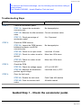
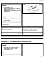
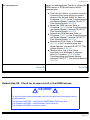
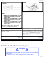
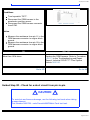
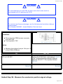
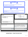
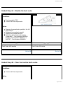
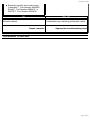
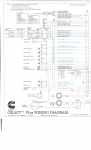
30/04/09 6:26 PM
FAULT CODE 432 (SSS)
Accelerator Pedal Circuit
Overview
CODE
Fault Code: 432
PID: P091
SPN: 91
FMI: 13
LAMP: Red
SRT: 00-612
REASON
EFFECT
No voltage detected at idle validation on-idle signal pin 6 of the
OEM harness when voltage at accelerator position signal pin 11 of
OEM harness indicates pedal is not at idle or no voltage detected
at idle validation off-idle signal pin 9 of the OEM harness when
voltage at accelerator position signal pin 11 of the OEM harness
indicates pedal is at rest.
Engine
will only
idle.
Accelerator Pedal Circuit
SMALL | MEDIUM | LARGE
Circuit Description
The accelerator pedal assembly relays the accelerator percentage needed to the electronic control
module (ECM).
Page 1 of 15
30/04/09 6:26 PM
Component Location
The accelerator position sensor is located on the accelerator pedal.
Shop Talk
Confirm that the idle validation switch (IVS) is properly calibrated. Refer to the manufacturer's
procedures for adjustment information.
Make sure there are no external circuits hooked into the accelerator position sensor circuit and
that there are no signs of tampering in the circuit.
If all the wiring and the sensor checks look good, replace the accelerator position sensor and
the idle validation switch circuit wires, between the accelerator pedal and ECM, with new
wires. Run the wires through or around the bulkhead without using the bulkhead connector.
Test the truck with the test wires in place. If the fault clears, replace the OEM harness. Seal
the openings in the bulkhead around the connector and the wires to prevent toxic and noxious
fumes from seeping into the cab. Verify that the three accelerator position sensor circuit wires
are twisted together. Check that the three idle validation switch circuit wires are twisted
together.
The ECM and accelerator pedal assembly must be electrically calibrated to each other for
proper engine response. The ECM and accelerator pedal assembly must be calibrated when
an accelerator pedal is initially installed, replaced, when an ECM is replaced, when a new
calibration is downloaded to the ECM, and when the accelerator pedal wiring is disconnected
while the vehicle keyswitch is “ON”.
With keyswitch “ON” gradually push the accelerator to the floor and release. Depress and
release the accelerator pedal three times. This procedure will recalibrate the ECM and
accelerator pedal.
Confirm with OEM that the throttle is within OEM specifications for TPS voltage or resistance
at idle to off-idle transition.
Depressing the throttle pedal while starting the engine is not necessary nor advised.
Additional fueling is not possible until the engine reaches idle, and in older versions of
software, depressing the throttle pedal could cause Fault Code 432 in some situations.
Cautions and Warnings
CAUTION
To avoid damaging a new ECM, all other active fault codes must be
investigated prior to replacing the ECM.
CAUTION
To avoid pin and harness damage, use the following test leads when taking
a measurement:
Part Number 3822758 - male Deutsch/AMP/Metri-Pack test lead
Page 2 of 15
30/04/09 6:26 PM
Part Number 3823995 - male Weather-Pack test lead
Part Number 3823996 - female Weather-Pack test lead
Part Number 3824892 - breakout cable.
CAUTION
To avoid pin and harness damage, use this test lead when taking a
measurement:
Part Number 3824892 - breakout cable.
CAUTION
To avoid pin and harness damage, use the following test leads when taking
a measurement:
Part Number 3822758 - male Deutsch/AMP/Metri-Pack test lead
Part Number 3823995 - male Weather-Pack test lead
Part Number 3824892 - breakout cable.
CAUTION
To avoid pin and harness damage, use the following test lead when taking a
measurement:
Part Number 3822758 - male Deutsch/AMP/Metri-Pack test lead.
CAUTION
To avoid pin and harness damage, use the following test leads when taking
a measurement:
Part Number 3822758 - male Deustch/AMP/Metri-Pack test lead.
CAUTION
Page 3 of 15
30/04/09 6:26 PM
To avoid pin and harness damage, use the following test lead when taking a
measurement:
Part Number 3823996 - female Weather-Pack test lead.
Troubleshooting Steps
STEPS
STEP 1.
SPECIFICATIONS
Check the accelerator pedal.
STEP 1A. Inspect the accelerator
connector pins.
No damaged pins
STEP 1B. Measure the idle resistance Correct resistance value
value.
STEP 1C. Check percentage of
accelerator pedal.
STEP 2.
STEP 3.
STEP 4.
3 to 10 percent
Check the OEM harness.
STEP 2A. Inspect the OEM harness,
bulkhead connector, and ECM
connector pins.
No damaged pins
STEP 2B. Check for an open circuit.
Less than 10 ohms
STEP 2C. Check for a short circuit to
ground.
More than 100k ohms
STEP 2D. Check for a short circuit
from pin-to-pin.
More than 100k ohms
Check the ECM.
STEP 3A. Check the voltage supply.
4.75 to 5.25 VDC
STEP 3B. Measure the accelerator
position signal voltage.
Less than one (1) VDC
Clear the fault code.
STEP 4A. Disable the fault code.
Fault Code 432 inactive
STEP 4B. Clear the inactive fault
codes.
All faults cleared
Guided Step 1 - Check the accelerator pedal.
Page 4 of 15
30/04/09 6:26 PM
Guided Step 1A - Inspect the accelerator connector pins.
Conditions
Turn keyswitch “OFF”.
Disconnect the accelerator from the OEM
harness.
Flush and clean the connector pins using
electronic contact cleaner, Part Number
3824510.
Action
bent or broken pins
pushed back or expanded pins
corroded pins
moisture in or on the connector
missing or damaged seals
dirt or debris in or on the connector pins.
OK
NOT OK
No damaged pins
Repair or replace the accelerator pedal
assembly. Refer to the OEM Troubleshooting
and Repair Manual.
Go to 1B
Go to 4A
Guided Step 1B - Measure the idle resistance value.
CAUTION
To avoid pin and harness damage, use this test lead when taking a
measurement:
Part Number 3824892 - breakout cable.
Page 5 of 15
30/04/09 6:26 PM
Conditions
Turn keyswitch “OFF”.
Install the breakout cable, Part Number
3824892, to the SSS.
Do not connect the breakout cable to the
OEM harness.
SMALL | MEDIUM | LARGE
Action
With the accelerator pedal released (onidle), measure the resistance from pin 3
(APS signal) to pin 4 (APS return) on the
breakout cable.
Note: Resistance value can be the same as the
Idle Resistance Value stamped on the SSS
cover, ±20 ohms.
OK
NOT OK
Correct resistance value
Replace the SSS. Refer to the OEM
Troubleshooting and Repair Manual.
Go to 2A
Go to 4A
Guided Step 1C - Check percentage of accelerator pedal.
Conditions
Disconnect the accelerator position
sensor at the accelerator pedal.
Turn keyswitch “ON”.
Action
Refer to Procedure 019-086 for method
Page 6 of 15
30/04/09 6:26 PM
to check the pedal.
OK
NOT OK
3 to 10 percent
Does not meet specifications. Replace
accelerator pedal assembly. Refer to OEM
manufacturer for procedure.
Go to 2A
Go to 4A
Guided Step 2 - Check the OEM harness.
Guided Step 2A - Inspect the OEM harness, bulkhead connector, and ECM
connector pins.
Conditions
Turn keyswitch "OFF".
Disconnect the OEM harness connector
from the ECM.
Flush and clean the connectors using
electronic contact cleaner, Part Number
3824510.
Action
bent or broken pins
pushed back or expanded pins
corroded pins
moisture in or on the connector
missing or damaged seals
dirt or debris in or on the connector pins.
OK
NOT OK
Page 7 of 15
30/04/09 6:26 PM
No damaged pins
Repair the damaged pins. Repair or replace the
OEM harness or ECM, whichever has the
damaged pins.
Flush the dirt, debris, or moisture from the
connector pins using electronic contact
cleaner, Part Number 3824510. Refer to
Procedure 019-203 in the Troubleshooting
and Repair Manual, Industrial CELECT™
Plus System Bulletin 3666130.
Repair the OEM harness. Refer to
Procedure 019-203 in the Troubleshooting
and Repair Manual, Industrial CELECT™
Plus System Bulletin 3666130.
Replace the OEM harness. Refer to
Procedure 019-071 in the Troubleshooting
and Repair Manual, Industrial CELECT™
Plus System Bulletin 3666130.
Replace the ECM. Refer to Procedure
019-031 in the Troubleshooting and
Repair Manual, Industrial CELECT™ Plus
System Bulletin 3666130.
Replace the o-ring on the 28-pin
connector if it is damaged or missing.
Refer to Procedure 019-203 in the
Troubleshooting and Repair Manual,
Industrial CELECT™ Plus System Bulletin
3666130.
Go to 2B
Go to 4A
Guided Step 2B - Check for an open circuit in the OEM harness.
CAUTION
To avoid pin and harness damage, use the following test leads when taking
a measurement:
Part Number 3822758 - male Deutsch/AMP/Metri-Pack test lead
Part Number 3823995 - male Weather-Pack test lead
Part Number 3824892 - breakout cable.
Page 8 of 15
30/04/09 6:26 PM
Conditions
Turn keyswitch "OFF".
Disconnect the OEM harness connector
from the ECM.
Disconnect the OEM harness from the
accelerator position sensor.
SMALL | MEDIUM | LARGE
Action
Measure the resistance from pin 18 of the
OEM harness connector to pin 5 of the
breakout cable.
Measure the resistance from pin 11 of the
OEM harness connector to pin 3 of the
breakout cable.
Measure the resistance from pin 19 of the
OEM harness connector to pin 1 of the
breakout cable.
Note: Install breakout cable, Part Number
3824892, for SSS accelerator pedals.
OK
NOT OK
Less than 10 ohms
Replace the OEM harness. Refer to Procedure
019-071 in the Troubleshooting and Repair
Manual, Industrial CELECT™ Plus System
Bulletin 3666130.
Go to 2C
Go to 4A
Guided Step 2C - Check for a short circuit to ground.
CAUTION
To avoid pin and harness damage, use the following test lead when taking a
measurement:
Part Number 3822758 - male Deutsch/AMP/Metri-Pack test lead.
Page 9 of 15
30/04/09 6:26 PM
Conditions
Turn keyswitch "OFF".
Disconnect the OEM harness to the
accelerator position sensor.
Disconnect the OEM harness connector
from ECM.
SMALL | MEDIUM | LARGE
Action
Measure the resistance from pin 11 in the
OEM harness connector to engine block
ground.
Measure the resistance from pin 18 in the
OEM harness connector to engine block
ground.
OK
NOT OK
More than 100k ohms
Replace the OEM harness. Refer to Procedure
019-071 in the Troubleshooting and Repair
Manual, Industrial CELECT™ Plus System
Bulletin 3666130.
Go to 2D
Go to 4A
Guided Step 2D - Check for a short circuit from pin-to-pin.
CAUTION
To avoid pin and harness damage, use the following test leads when taking
a measurement:
Part Number 3822758 - male Deustch/AMP/Metri-Pack test lead.
Page 10 of 15
30/04/09 6:26 PM
Conditions
Turn keyswitch "OFF".
Disconnect the OEM harness from the
accelerator position sensor.
Disconnect the OEM harness connector
from the ECM.
Set all switches in cab to “OFF” or
“NEUTRAL” position - open service brake
switch, AC pressure switch, and clutch
switch, or unplug them.
Diagnostic switch not in diagnostic mode.
SMALL | MEDIUM | LARGE
Action
Measure the resistance from pin 18 in the
OEM harness to all other pins in the
connector.
Measure the resistance from pin 11 in the
OEM harness to all other pins in the
connector.
Measure the resistance from pin 19 in the
OEM harness to all other pins in the
connector.
OK
NOT OK
More than 100k ohms
Replace the OEM harness. Refer to Procedure
019-071 in the Troubleshooting and Repair
Manual, Industrial CELECT™ Plus System
Bulletin 3666130.
Go to 3A
Go to 4A
Guided Step 3 - Check the ECM.
Guided Step 3A - Check the voltage supply.
Page 11 of 15
30/04/09 6:26 PM
CAUTION
To avoid damaging a new ECM, all other active fault codes must be
investigated prior to replacing the ECM.
CAUTION
To avoid pin and harness damage, use the following test lead when taking a
measurement:
Part Number 3823996 - female Weather-Pack test lead.
Conditions
Disconnect the OEM harness connector
from the ECM.
Turn keyswitch “ON”.
SMALL | MEDIUM | LARGE
Action
Measure the voltage from pin 18 to pin 19
of the ECM's OEM port.
OK
NOT OK
4.75 to 5.25 VDC
Replace the ECM. Refer to Procedure 019-031
in the Troubleshooting and Repair Manual,
Industrial CELECT™ Plus System Bulletin
3666130.
Go to 3B
Go to 4A
Guided Step 3B - Measure the accelerator position signal voltage.
Page 12 of 15
30/04/09 6:26 PM
CAUTION
To avoid damaging a new ECM, all other active fault codes must be
investigated prior to replacing the ECM.
CAUTION
To avoid pin and harness damage, use the following test lead when taking a
measurement:
Part Number 3823996 - female Weather-Pack test lead.
Conditions
Disconnect the OEM harness connector
from the ECM.
Turn keyswitch “ON”.
SMALL | MEDIUM | LARGE
Action
Measure the voltage from pin 11 to pin 19
of the ECM OEM port.
OK
NOT OK
Less than one (1) VDC
Replace the ECM. Refer to Procedure 019-031
in the Troubleshooting and Repair Manual,
Industrial CELECT™ Plus System Bulletin
3666130.
Go to 4A
Go to 4A
Guided Step 4 - Clear the fault code.
Page 13 of 15
30/04/09 6:26 PM
Guided Step 4A - Disable the fault code.
Conditions
Turn keyswitch “ON”.
Connect all the components.
SMALL | MEDIUM | LARGE
Action
Depress the accelerator pedal to the full
fuel position.
Release the accelerator pedal.
Repeat this procedure twice.
Read the active fault codes using
Compulink™, Part Number 3823549,
Echek™, Part Number 3824437, or
INSITE™, Part Number 3824638.
OK
NOT OK
Fault Code 432 inactive
Fault Code 432 active.
Go to 4B
Go to 1A
Guided Step 4B - Clear the inactive fault codes.
Conditions
Connect all the components.
Action
Page 14 of 15
30/04/09 6:26 PM
Erase the inactive fault codes using
Compulink™, Part Number 3823549,
Echek™, Part Number 3824437, or
INSITE™, Part Number 3824638.
OK
NOT OK
All faults cleared
Troubleshoot any remaining active fault codes.
Repair complete
Appropriate troubleshooting chart
Last Modified: 03-Nov-2003
Page 15 of 15