1
SENSOR 0.7
VISION-BASED NAVIGATION SOFTWARE:
TECHNICAL MANUAL
By
Stephen D. Fleischer
September 2000
Copyright c 2000 by Stephen D. Fleischer
All Rights Reserved.
ii
Contents
1 User's Guide
1.1
1.2
1.3
1.4
Overview . . . . . . . . . . . .
Application Startup . . . . . .
Application Execution: Modes
Graphical User Interface . . . .
1.4.1 Mosaic File Type . . . .
1.4.2 DIB File Type . . . . .
1.4.3 Menus . . . . . . . . . .
1.4.4 Dialog Boxes . . . . . .
1.4.5 Toolbar . . . . . . . . .
1.5 Initialization File . . . . . . . .
1.6 Stethoscope . . . . . . . . . . .
.
.
.
.
.
.
.
.
.
.
.
.
.
.
.
.
.
.
.
.
.
.
.
.
.
.
.
.
.
.
.
.
.
2 Software Architecture Overview
.
.
.
.
.
.
.
.
.
.
.
.
.
.
.
.
.
.
.
.
.
.
.
.
.
.
.
.
.
.
.
.
.
.
.
.
.
.
.
.
.
.
.
.
2.1 Introduction . . . . . . . . . . . . . . . . . .
2.2 Advanced Vision Processor (AVP) Library .
2.3 Sensor 0.7 Application . . . . . . . . . . . .
2.3.1 AVP Engine Thread . . . . . . . . .
2.3.2 GUI Thread . . . . . . . . . . . . . .
2.3.3 Communications Link Threads . . .
2.3.4 Data Logger Thread . . . . . . . . .
iii
.
.
.
.
.
.
.
.
.
.
.
.
.
.
.
.
.
.
.
.
.
.
.
.
.
.
.
.
.
.
.
.
.
.
.
.
.
.
.
.
.
.
.
.
.
.
.
.
.
.
.
.
.
.
.
.
.
.
.
.
.
.
.
.
.
.
.
.
.
.
.
.
.
.
.
.
.
.
.
.
.
.
.
.
.
.
.
.
.
.
.
.
.
.
.
.
.
.
.
.
.
.
.
.
.
.
.
.
.
.
.
.
.
.
.
.
.
.
.
.
.
.
.
.
.
.
.
.
.
.
.
.
.
.
.
.
.
.
.
.
.
.
.
.
.
.
.
.
.
.
.
.
.
.
.
.
.
.
.
.
.
.
.
.
.
.
.
.
.
.
.
.
.
.
.
.
.
.
.
.
.
.
.
.
.
.
.
.
.
.
.
.
.
.
.
.
.
.
.
.
.
.
.
.
.
.
.
.
.
.
.
.
.
.
.
.
.
.
.
.
.
.
.
.
.
.
.
.
.
.
.
.
.
.
.
.
.
.
.
.
.
.
.
.
.
.
.
.
.
.
.
.
.
.
.
.
.
.
.
.
.
.
.
.
.
.
.
.
.
.
.
.
.
.
.
.
.
.
.
.
.
.
.
.
.
.
.
.
.
.
.
.
.
.
.
.
.
.
.
.
.
.
.
.
.
.
.
.
.
.
.
.
.
.
.
.
.
.
.
.
.
.
.
.
1
1
2
3
5
5
6
7
12
20
21
28
29
29
30
30
31
32
33
34
3 AVP Library
3.1 Assumptions and Constraints . . . . . . . . . .
3.2 Solution . . . . . . . . . . . . . . . . . . . . . .
3.2.1 Sub-Image Texture-Based Registration .
3.2.2 Image Processing Pipeline . . . . . . . .
3.2.3 Mosaicking Process . . . . . . . . . . . .
.
.
.
.
.
4 AVP Engine Thread
4.1 Data Flow Design and Implementation . . . . . .
4.1.1 Components . . . . . . . . . . . . . . . .
4.1.2 Signals . . . . . . . . . . . . . . . . . . . .
4.1.3 Parameters . . . . . . . . . . . . . . . . .
4.1.4 Adding Components/Signals/Parameters
4.2 System Geometry/Frame Descriptions . . . . . .
4.3 Signal Descriptions . . . . . . . . . . . . . . . . .
4.4 Parameter Descriptions . . . . . . . . . . . . . .
4.5 Component Descriptions . . . . . . . . . . . . . .
4.6 Inter-Thread Communication . . . . . . . . . . .
4.6.1 Thread Messaging . . . . . . . . . . . . .
4.6.2 External Access for Signals . . . . . . . .
4.6.3 External Access for Parameters . . . . . .
4.7 Stethoscope . . . . . . . . . . . . . . . . . . . . .
5 GUI Thread
5.1 Documents . . . . . . . .
5.1.1 DIB Document . .
5.1.2 Mosaic Document
5.2 Views . . . . . . . . . . .
5.3 Dialog Boxes . . . . . . .
.
.
.
.
.
.
.
.
.
.
.
.
.
.
.
.
.
.
.
.
.
.
.
.
.
.
.
.
.
.
iv
.
.
.
.
.
.
.
.
.
.
.
.
.
.
.
.
.
.
.
.
.
.
.
.
.
.
.
.
.
.
.
.
.
.
.
.
.
.
.
.
.
.
.
.
.
.
.
.
.
.
.
.
.
.
.
.
.
.
.
.
.
.
.
.
.
.
.
.
.
.
.
.
.
.
.
.
.
.
.
.
.
.
.
.
.
.
.
.
.
.
.
.
.
.
.
.
.
.
.
.
.
.
.
.
.
.
.
.
.
.
.
.
.
.
.
.
.
.
.
.
.
.
.
.
.
.
.
.
.
.
.
.
.
.
.
.
.
.
.
.
.
.
.
.
.
.
.
.
.
.
.
.
.
.
.
.
.
.
.
.
.
.
.
.
.
.
.
.
.
.
.
.
.
.
.
.
.
.
.
.
.
.
.
.
.
.
.
.
.
.
.
.
.
.
.
.
.
.
.
.
.
.
.
.
.
.
.
.
.
.
.
.
.
.
.
.
.
.
.
.
.
.
.
.
.
.
.
.
.
.
.
.
.
.
.
.
.
.
.
.
.
.
.
.
.
.
.
.
.
.
.
.
.
.
.
.
.
.
.
.
.
.
.
.
.
.
.
.
.
.
.
.
.
.
.
.
.
.
.
.
.
.
.
.
.
.
.
.
.
.
.
.
.
.
.
.
.
.
.
.
.
.
.
.
.
.
.
.
.
.
.
.
.
.
.
.
.
.
.
.
.
.
.
.
.
.
.
.
.
.
.
.
.
.
.
.
.
.
.
.
.
.
.
.
.
.
.
.
.
.
.
.
.
.
.
.
.
.
.
.
.
.
.
.
.
.
.
.
.
.
.
.
.
.
.
.
.
.
.
.
.
.
.
.
.
.
.
.
.
.
.
.
.
.
.
35
35
37
37
40
41
43
43
44
45
46
46
48
50
55
57
63
65
66
68
70
71
72
72
72
73
74
6 Communications Link Threads
6.1
6.2
6.3
6.4
6.5
AVPNet . . . . . . . . . . . . . . .
ComputeServerLink . . . . . . . .
SpaceFrameLink (FlightTableLink)
OtterLink . . . . . . . . . . . . . .
VentanaSerialLink . . . . . . . . .
.
.
.
.
.
.
.
.
.
.
.
.
.
.
.
.
.
.
.
.
.
.
.
.
.
.
.
.
.
.
.
.
.
.
.
.
.
.
.
.
.
.
.
.
.
.
.
.
.
.
.
.
.
.
.
.
.
.
.
.
.
.
.
.
.
.
.
.
.
.
.
.
.
.
.
.
.
.
.
.
.
.
.
.
.
.
.
.
.
.
.
.
.
.
.
.
.
.
.
.
.
.
.
.
.
.
.
.
.
.
.
.
.
.
.
75
75
76
77
78
79
7 Data Logger Thread
80
8 Distributed Software Components
84
Bibliography
99
7.1 Synchronous Data Log . . . . . . . . . . . . . . . . . . . . . . . . . . . . . .
7.2 Asynchronous Data Log . . . . . . . . . . . . . . . . . . . . . . . . . . . . .
8.1 Smoother . . . . . . . . . . . . . . . . . . . . . . . . . . . . . . . . . . . . .
8.2 Space Frame Network Node . . . . . . . . . . . . . . . . . . . . . . . . . . .
8.3 OTTER Network Node . . . . . . . . . . . . . . . . . . . . . . . . . . . . .
v
81
82
84
91
98
Chapter 1
User's Guide
This technical manual serves two purposes: it is designed to be both a user's guide and
a programmer's manual for the Sensor (version 0.7) application. This rst chapter serves
as the user's guide, and it explains how to start and run the application, load and store
mosaics, and use the graphical user interface. The remaining chapters provide an in-depth
discussion of the software implementation details, for those who wish to modify the code
for future experiments and demonstrations.
The user's guide (Chapter 1) assumes the reader has a basic knowledge of Windows concepts, such as windows and window management, mouse actions, application execution, les
and directories, etc. In addition to these requirements, the programmer's manual (Chapters 2{8) assumes familiarity with the Microsoft Visual Studio development environment,
the Microsoft Visual C++ compiler, the MFC (Microsoft Foundation Classes) framework,
and multi-threaded programming concepts.
1.1 Overview
The Sensor application performs real-time video mosaicking and visual map-based navigation for mobile robots, including real-time vehicle state estimation and control. This
software runs on any PC with Windows NT 4.0 and a Matrox Meteor digitizer board. To
interface with external hardware, the application requires a live video input and either an
1
CHAPTER 1. USER'S GUIDE
2
ethernet or serial connection for bi-directional communications. In its current conguration (without code modication), Sensor is capable of interfacing with the following three
experimental hardware systems: the Space Frame, the OTTER AUV, and the Ventana
ROV.
1.2 Application Startup
To start the Sensor application, double-click on the Sensor.exe le within the Release/
subdirectory of the source code, or execute it from with Visual Studio. Be sure that the
parameters.ini is located either in the same directory as the Sensor.exe executable (for standalone execution), in the working directory (if a shortcut to the executable has been dened,
such as on the Start Menu or desktop), or within the source code hierarchy (for execution
from within Visual Studio). Otherwise, default values for the parameters.ini entries will be
used. (See Section 1.5 for more information on the parameters.ini initialization le.)
Upon successful startup, a Conguration dialog box will pop-up requesting the user to
specify the intended application. Choose the radio button that corresponds to the target
hardware: Flight Table (= Space Frame), OTTER, or Ventana. The Sensor application
can be executed for testing in the absence of actual hardware in this case, be aware that
the inputs expected from the robotic system may be undened.
In addition to the radio buttons, there is an \Enable smoother" checkbox. If this box
is checked, an optimal re-alignment procedure will be enabled during mosaic creation. This
procedure detects when the mosaic crosses back upon itself, aligns the overlapping images
at the crossover point, and re-aligns all other images in the mosaic to maintain the internal
consistency of the mosaic map. Note that only the crossover detection and correlation
(i.e. alignment) is performed automatically when this box is checked to perform the nal
smoothing (i.e. re-alignment), an external compute server must be running (see Section 8.1).
Note that in its current state, the mosaicking procedure is more robust without the smoother
enabled (and thus probably more useful unless the user is quite familiar with the internal
CHAPTER 1. USER'S GUIDE
3
workings of the mosaicking/smoothing procedure). For more details on the smoother, refer
to Steve Fleischer's thesis. 1].
After clicking OK to nish the Conguration dialog box, a New dialog box appears
with two options: Mosaic and Dib. This determines what type of new le will be created
automatically within the Sensor application (see Sections 1.4.1 and 1.4.2 for more information on le types). Clicking on OK will automatically create a new le of whatever type
was highlighted. Clicking on Cancel will start the application without opening any new
les. For most purposes, it is easiest to just click OK to create a new Mosaic le, so new
mosaics can be created immediately. (New les always can be created once the application
is running.)
At this point, the main application window should open, and a few seconds later, the
long rectangular Output Display dialog box will open. Due to a timing bug among the
multiple threads that I believe is contained within Windows code (not the Sensor code), I
recommend that you do not click on any buttons or menus or try to move either window
until numbers show up in the small edit boxes on the right side of the Output Display dialog
box. (The only detrimental eect I've seen so far is that some of the graphic overlays do
not display properly, but there may be other unpredictable side eects.)
1.3 Application Execution: Modes
Once the application is running, two dierent sets of tasks can be performed: online video
mosaicking and navigation and oine retrieval, viewing, and storage of Mosaic and DIB
les. The second set of tasks will be described in Sections 1.4.1 and 1.4.2 within the context
of le types and their manipulation. The rst set of tasks (which are the primary goal of
the Sensor application) are dened and controlled by several modes of execution.
Currently, the application can be executing in one of ve dierent modes. Each mode is
a superset of the previous one in other words, every mode performs the same computations
and produces the same outputs as the previous mode, plus additional computations and
outputs. Here are descriptions of the ve modes:
CHAPTER 1. USER'S GUIDE
4
Idle In this mode, all sample loops are running, but SLoG ltering of the live video image is
the only computation performed. Thus, the sample rates for every loop in the system
can be displayed on the right side of the Output Display dialog box.
Image Tracker When this mode is started (or reset), a single reference image is taken from
the live video stream. All subsequent live images are correlated with this reference
image to calculate an image displacement that is output by the main computation
thread for display in the GUI.
Position Sensor This mode creates a video mosaic by snapping a new reference image
whenever the vehicle moves beyond the eld of view (FOV) of the previous reference
image. This new reference image is already aligned with the previous reference image,
so it is added to the evolving mosaic. Through this mosaic creation process, the
current global state (i.e. position + orientation) of the vehicle (relative to the center
of the initial image in the mosaic) is estimated and displayed in the GUI. (In the Space
Frame conguration, this global state is sent directly to the hardware to control the
Space Frame.) Also, if the smoother is enabled, crossover detection and correlation
of loops in the mosaic is attempted.
Error Sensor The vehicle state error is determined by calculating the dierence between
the desired vehicle state (which can be user-specied within the GUI) and the current
vehicle state. (In the OTTER conguration, the vehicle state error is sent directly to
OTTER's on-board controllers.)
Controller A control signal is generated for the three translational degrees-of-freedom
(DOF) by using the vehicle state error as input to any of several pre-dened controllers,
whose gains can be modied online from the GUI. (In the Ventana conguration, the
control signals are sent to Ventana to control its thrusters directly.)
The current mode of execution can be changed from either the Modes menu or one of
the ve mode buttons on the toolbar. One can go from any mode to any other mode in
CHAPTER 1. USER'S GUIDE
5
addition, the current mode can be reset by clicking on the same mode again (for instance,
to complete the current mosaic and start a new one).
1.4 Graphical User Interface
This section describes the graphical user interface (GUI) that allows user intervention and
modication of the real-time computation loops within the Sensor application. It includes
detailed descriptions of the le types, menus, and dialog boxes that control the Sensor
application. However, it is recommended that the user read Chapters 2 and 3 to gain a full
understanding of the relevance of each of the GUI controls.
1.4.1 Mosaic File Type
The Mosaic le type was dened specically for this application. It is a format for storing on
disk the mosaics created during online execution. The Mosaic format is not actually a single
le it is a set of les consisting of a single .mos le, and a .dib le for every image contained
within the mosaic. The .mos le is a binary data le that describes to the application how
to re-construct the mosaic from the series of .dib image les.
Mosaic Creation
Although several Mosaic les may be open within Sensor at once, exactly one of these les is
designated by the application to be the \active" Mosaic le. (If no Mosaic les are open, a
new one must be created and automatically made active before a new mosaic can be created
online.) Any mosaic updates received from the main computation thread are always added
to the active mosaic. When changing or resetting modes, the currently active mosaic is set
to inactive, a new mosaic le is opened, and it is set to active.
Mosaic Storage and Retrieval
Just like any other \le", a Mosaic can be saved to disk by using either the Save or Save
As... menu items or the Save toolbar button. However, since the Mosaic is actually a set of
CHAPTER 1. USER'S GUIDE
6
les, it is recommended that each Mosaic be saved in its own dedicated subdirectory. When
the Save dialog box pops up, it asks for a lename, that corresponds to the name of the
.mos le. The .dib les are then named image0.dib, image1.dib, ... and stored in the same
directory as the .mos le. Note that upon exiting Sensor, it will ask to save every unsaved
Mosaic le.
To retrieve a Mosaic, use the Open... menu item or toolbar button to open the .mos
le, selecting the *.mos File Type in the Open dialog box if necessary. Note that all of the
proper .dib les must be in the same directory as the .mos le for retrieval to be successful.
As explained later in this Section under the description of Sensor's menus, it is also
possible to export a Mosaic as a single .dib image le. This is a more compact representation
of the mosaic, useful for importing the mosaic as a gure into other applications, such as
PowerPoint or LaTex.
1.4.2 DIB File Type
The DIB (Device-Independent Bitmap) le type is a standard Windows image le format.
It has been chosen as the format in which to store individual images of the mosaic.
DIB Creation
DIB les cannot be directly created by the user through the Sensor application. They are
created indirectly whenever a mosaic is saved to disk: each of the individual images is saved
in a .dib le. Also, a .dib le is created when an entire mosaic is exported as a single image
le.
DIB Storage and Retrieval
While DIB les cannot be directly created, existing DIB les can be retrieved and stored by
the Sensor application. These actions can be accomplished through the standard Open...,
Save, and Save As... menu items/toolbar buttons, by selecting *.dib as the desired le type.
CHAPTER 1. USER'S GUIDE
7
1.4.3 Menus
The menu bar at the top of the main Sensor window permits the user to control the functionality of the application. Depending on whether no individual DIB or Mosaic windows are
open, a DIB window is open and highlighted, or a Mosaic window is open and highlighted,
the menu bar changes to re ect the functionality available for that particular situation.
This section explains each of the menu options in the menu bar hierarchy.
File
This menu contains options for le manipulation, including storage, retrieval, and printing.
New This is a standard Windows menu option. It opens a new le: after clicking on New,
a dialog box opens so the user can specify the type of le to open (Mosaic or DIB).
Open... This is a standard Windows option. It opens an existing le: after clicking on
Open..., a dialog box opens so the user can specify the lename, using the standard Windows
exploring and ltering capabilities.
Close This is a standard Windows option. It closes the le window that is currently
highlighted. If the le has never been saved to disk, a dialog box will open to ask if you
want to save the le rst. Note: if the \active" Mosaic window (in the sense that it will
be the one to receive new images from the online mosaicking process) is highlighted, it
cannot be closed, and a pop-up message will indicate that if the user attempts to close it.
Remember that there is always an \active" Mosaic window, unless the application has just
started and there are no Mosaic windows open.
Save This is a standard Windows option. It saves a le to the same location under which
it was last previously saved. If the le has never been saved, this option will behave as if
the Save As... menu item was selected.
CHAPTER 1. USER'S GUIDE
8
Save As... This is a standard Windows option. It allows the user to save a le to a
specied location, regardless of whether the le has never been saved previously or has
been saved previously to a dierent location. When this menu item is selected, a dialog box
opens that allows the user to specify the lename, using the standard Windows exploring
and ltering capabilities.
Import This submenu provides an option for importing data into the Sensor application.
It is present only if a le window of type Mosaic is highlighted.
Mosaic Data... This menu item allows the user to import a set of data from a le that
modies the alignment of the currently highlighted Mosaic. When this menu item
is selected, a dialog box opens that allows the user to select the lename containing
the new alignment data. This le must have exactly the following format (little or
no error-checking is performed): it must be a plain text le there must be exactly
one line for every image in the highlighted Mosaic each line consists of two decimal
numbers, namely, the and global position of the center of the relevant image, in
meters. The Sensor application reads in this data and uses existing data within the
Mosaic to align the mosaic images according to the new image positions.
x
y
Export This submenu provides options for exporting data from the Sensor application in
formats other than the standard .mos le. It is present only if a le window of type Mosaic
is highlighted.
Corrected mosaic as DIB... This allows the user to export the currently highlighted
Mosaic as a single DIB image le. When this menu item is selected, a dialog box
opens that allows the user to select the location and lename for the new DIB le.
The mosaic is \corrected" in the sense that the conversion to global coordinates and
units (meters) has been taken into account, and if the smoother is enabled, crossover
detection/correlation and smoothing (if the external compute server is running) has
been performed. It is the same mosaic that appears in the Mosaic window. Of all
CHAPTER 1. USER'S GUIDE
9
the import and export functions, this one will be most useful to ordinary users of the
Sensor application.
Corrected mosaic data... This allows the user to export the mosaic alignment data for
the currently highlighted Mosaic into a text le. When this menu item is selected, a
dialog box opens that allows the user to select the location and lename for the new
text le. The text le format is as follows: there is one line in the le for each image
in the mosaic each line contains the following numbers: the 2-D local displacement
between this image and the previous one (m ImageLocalDisp.x, .y), the variances of
these measurements (m ImageLocalDispVar.x, .y), the
location of the camera in
global coordinates that are aligned with the terrain (m CameraState TF.x, .y), and
the variances of these measurements (m CameraState TFVar.pp0]0], .pp1]1]). The
denition of \corrected" is explained above.
x y
Uncorrected mosaic as DIB... This is identical to \Corrected mosaic as DIB...", except
that mosaic is uncorrected, i.e. the data obtained before any conversion to global
coordinates or smoothing is used to create the mosaic.
Uncorrected mosaic data... This is identical to \Corrected mosaic data...", except that
the data exported is uncorrected, as explained above.
Print... This is a standard Windows option. It allows the user to print the highlighted
le window (either Mosaic or DIB) as an image to the selected printer. When this menu
item is selected, the standard Windows Print dialog box appears.
Print Preview This is a standard Windows option. When this menu item is selected, a
preview of the le as it would look printed is displayed. BUG WARNING: I don't think
this works correctly for either Mosaic or DIB les.
Print Setup... This is a standard Windows option. When this menu item is selected, the
standard Windows Print Setup dialog box appears.
CHAPTER 1. USER'S GUIDE
10
Recent Files This is a standard Windows option. These items provide a list of the most
recently opened les. This list can be used to quickly access common les by selecting the
desired le from the list.
Exit This is a standard Windows option. Selecting this menu item will exit the entire
Sensor application, closing all open windows and asking if any unsaved les should be saved
to disk.
Edit
This menu is present only if there is a Mosaic or DIB window open. It is used to perform
the standard Windows Cut, Copy, Paste, and Undo operations to and from the Windows
Clipboard. However, I don't think any of these have been implemented for either DIB's or
Mosaic's: feel free to try it and see if anything happens.
View
This menu is a standard Windows option that controls whether the Toolbar on the top of
the main window and/or the Status Bar on the bottom of the main window is displayed.
Selecting the Toolbar or Status Bar menu item will toggle a check mark next to that item,
indicating whether to show or hide that item in the Sensor application's main window.
Window
This menu allows the user to manipulate the le windows within the main Sensor application
window. It is available only if there are one or more windows open (either Mosaic or DIB).
New Window This is a standard Windows option. This menu item creates a new window
that displays the same le as the currently highlighted window.
Cascade This is a standard Windows option. This menu item arranges all currently open
windows in an overlapping (i.e. cascading) format.
CHAPTER 1. USER'S GUIDE
11
Tile This is a standard Windows option. This menu item arranges all currently open
windows such that there is no window overlap and all windows cover an equal portion of
the available viewing area.
Arrange Icons This is a standard Windows option. This menu item arranges any iconied windows along a regular grid pattern.
Split This is a standard Windows option. This menu item is only available when a Mosaic
window is highlighted, and it splits the window into four sub-window that view the same
Mosaic le.
Refresh active mosaic This menu item forces a redraw of all windows that view the
currently active mosaic, in case new updates are not properly shown. I think this is now
obsolete, as all previous problems with automatic refresh of the mosaics seem to have been
xed.
Modes
This menu enables the user to switch between the ve execution modes of the Sensor
application, as described in Section 1.3. In this menu, a bullet appears next to the currently
active mode. To change modes, click on the new desired mode. Also, it is possible to reset
the current mode either by clicking on the active mode (the one with the bullet) or by
clicking on the \Reset current mode" menu item.
Controls
This menu enables the user to access the seven dialog boxes that control specic aspects
of the Sensor application. To open any of the dialog boxes, click on the appropriate menu
item within this menu. Each of the dialog boxes are described in detail in Section 1.4.4.
CHAPTER 1. USER'S GUIDE
12
Help
The items on this menu provide the standard Windows help functionality. While the help
functionality has been built in, no specic help for the Sensor application has been implemented. Feel free to try the menu items and see if you can nd any useful information (e.g.
help for the standard Windows options).
Data Log
This menu is only available if a Mosaic window is currently highlighted. It implements the
data logging functionality of the Sensor application. To start recording data, click on the
\Open" menu item. A dialog box will open to ask the location and lename to store the
data. The data is actually written into two text les. The rst le, whose name is specied
in the dialog box, receives synchronous data, i.e. data from every time step in the main
computation loop. The second le, whose name is the same as the rst with a \ param"
appended, receives asynchronous data when the data logging starts, the mode changes, or
new measurement lter/control values are set, the relevant parameters are written to this
le. To stop recording data, click on the \Close" menu item. Note that it is important to
remember to close the data le, since the size of the synchronous data le grows rapidly,
since data is recorded at 10{30 Hz.
The data log provides a level of detail that may not be useful for the common user. As
such, no attempt will be made to explain in this section the items that are stored in the
data logs interested users are referred to Chapter 7.
1.4.4 Dialog Boxes
All of the items that control or display the execution of the main computation thread and
peripheral threads have been grouped functionally into seven dialog boxes. This section
provides descriptions of the controls inside each of these dialog boxes. Note that many of
these controls get their default values from the parameters.ini initialization le (Section 1.5).
Thus, the initialization le enables modication of the default application behavior without
CHAPTER 1. USER'S GUIDE
13
recompilation, and the dialog boxes enables modication of the default behavior as the
application is running.
Image Acquisition
This dialog box controls the acquisition parameters of the image digitization process.
Brightness This slider bar controls the brightness of the digitized image. Its eect can
be seen in real-time if live image display is enabled in the Output Display dialog box and
the Sensor application is in Image Tracker (or greater) mode.
Contrast This slider bar controls the contrast of the digitized image. Its eect can be
seen in real-time if live image display is enabled in the Output Display dialog box and the
Sensor application is in Image Tracker (or greater) mode.
Image Processing
This dialog box controls the image ltering and correlation process.
Threshold This slider bar sets the threshold that determines whether the image correla-
tion data is valid or invalid. When the image processing pipeline compares the live image
with the reference image at every time step, it outputs both a relative displacement between
images and a condence value. This condence value is in the range 50{100%, where 50%
represents the correlation between two random images, and 100% is a perfect match. The
displacement data is considered invalid if the associated value falls below the threshold. In
Steve Fleischer's thesis, it was determined experimentally that 63% is approximately the
cuto between accurate and spurious data, so it is recommended that the threshold stay
set at this level. However, if it looks like (in the Output Display dialog box) the image
correlation is matching regions well, but the data is invalid, or vice versa, this value can be
changed.
CHAPTER 1. USER'S GUIDE
14
AVP Desired Sample Rate This edit box sets the desired execution rate for the lowest
level of computation, the AVP image processing library. Since images are digitized at 30
Hz, this low-level loop can run up to this speed. However, if the Sensor application is
running on a computer with limited computation power, the AVP loop may consume too
many resources, nearly starving the other threads of execution time. This eect can be seen
by the sample rates displayed in the Output Display dialog box, and it can be adjusted by
this control. Note: Because of the timing of this loop, the actual sample rate is slightly
lower than the desired sample rate that is specied in this edit box. Some trial-and-error
may be required to get exactly the desired sample rate. Also note: Since I attempt to
read in a number whenever something is typed into the edit box, you may nd it behaves
strangely - I should have added an \Apply" button. If you have trouble, just set this in the
parameters.ini le, since it is rarely necessary to change this value online anyway.
Mapping/Navigation
This dialog box controls the parameters relevant to the mosaicking process.
Manual Snap When creating a mosaic, the application automatically adds a new image
to the mosaic whenever the vehicle has moved far enough such that a specied minimum
overlap between images has been reached, or whenever the image correlation data remains
invalid for too long. This button allows the user to specify that a new image should be
snapped and added to the mosaic immediately, regardless of the criteria for automated
image snap.
Allowable Dropouts This parameter quanties the statement in the previous paragraph
that a new image is snapped if the image correlation data remains invalid for too long. If the
image correlation data at the current time step is determined to be invalid, the application
has no idea how far the vehicle has moved since the last time valid data is received, so it
assumes the vehicle has not moved at all, and it increments a counter. If the counter value
exceeds the allowable number of dropouts, as specied by this slider bar, the application
CHAPTER 1. USER'S GUIDE
15
decides to snap a new reference image in an attempt to restart the correlation process. The
tradeo is that minor dropouts can be ignored if the correlation process can re-acquire after
a dropout occurs, but signicant dropouts should be immediately corrected by resetting the
correlation process with a new reference image.
Serial Port Data
This dialog box displays the data received from Ventana via the serial port in real-time.
Thus, it is only relevant when physically connected to Ventana. The meaning of each of
the read-only edit boxes is either self-explanatory or unknown to the author, in which case
T.C. Dawe of MBARI can provide an explanation for each of these signals. If the signals
do not seem to be changing, a refresh button has been provided however, this button is
most likely obsolete, as bugs in the automatic refresh of the data at every time step seem
to have been xed.
Measurement Filter Parameters
Before using external input signals in computations, they are conditioned by various lters
to improve their smoothness and eliminate spurious data. This dialog box is used to modify
the parameters that control the input lters.
Sonar Altimeter Oset On Ventana, the sonar altimeter signal is multiplied by a scale
factor and then added to an oset value so that the nal result represents the range in
meters from the ocean oor to an appropriate point on the vehicle (usually the center of
the main camera upon which the altimeter is mounted). This edit box allows the user to
set the altimeter oset.
Sonar Altimeter Scale As explained above, this edit box allows the user to set the sonar
altimeter scaling factor.
CHAPTER 1. USER'S GUIDE
16
Vision X,Y Deadband Width In order to eliminate chatter on the image displacement
due to pixel-based quantization of the measurement, the raw measurements are ltered with
a type of deadband. Any measurements that are smaller than the width of the deadband
are set to zero larger measurements are unaected. This edit box sets the width of the
deadband.
Velocity Filter Cuto Frequency Both the vision and altimeter signals are used to
derive a velocity measurement through a process that includes a low-pass lter on the
velocity. This edit box sets the cuto frequency of that lter, that determines the tradeo
between signal latency and signal smoothness.
Use New Measurement Filter Parameters Whenever any of the above parameters
are changed through the edit boxes, this button must be pressed in order to apply the
changes.
Controller Parameters
This dialog box sets the parameters that are relevant to the vehicle controllers for each
degree of freedom. The user is able to set both the control mode and the control gains
through this dialog box.
The control mode for each DOF can be set independently. First, the user should choose
the X, Y, or Z radio button along the top row that corresponds to the desired DOF. Then,
the desired control mode can be specied by clicking on one of the six radio buttons on the
left. Note that if the user clicks on another DOF, the control mode radio buttons change
to re ect the current mode for that DOF.
The control gains are set independently of the radio buttons. Control gains for every
degree of freedom and/or every control mode can be set by typing in the desired values into
the appropriate edit boxes, then clicking on the \Apply New Control Parameters" button
to apply the new values, even if the controllers are currently active.
CHAPTER 1. USER'S GUIDE
17
No Control This control mode sets the control signal to zero at every time step for the
specied DOF. This enables independent testing of each DOF.
Constant Control This control mode sets the control signal to a constant value at every
time step (corresponding to a voltage in the 10 V range for Ventana). The output value
is equal to the value of p for the corresponding degree of freedom.
K
PD Control This control mode performs standard proportional-derivative control, using
the values of p and d for the proportional and derivative gain values, respectively.
K
K
PID Control This control mode performs standard proportional-derivative-integral con-
trol. It uses the same proportional and derivative gain values, p and d , as the PD
controller, and it also uses an integral control gain, i .
K
K
K
Lead Control This control mode implements a rst-order lead controller, and the dialog
box enables the user to specify the pole and zero placement, and the overall gain, l .
K
Sliding Mode Control This mode implements a sliding mode controller, using the four
parameters , , , and .
M
K
Slew Rate The control signals for every DOF are ltered with identical slew rate lters
before output, in order to minimize spiked signals that could result in thruster breakage.
The maximum rate of change of any control signal is dened by this slew rate parameter,
and its units are volts/sec for the case of Ventana.
Saturator Limit All of the control signals are ltered with identical saturators before
output, to guarantee that the signals do not exceed the thruster input voltages. This
parameter sets the upper and lower bound of the control signal.
Deadband Width To eliminate thruster propellers from constantly changing direction
due to noise around the origin, identical deadband lters have been implemented for each
CHAPTER 1. USER'S GUIDE
18
DOF control signal. All control values smaller than the deadband are set to zero, and this
parameter controls the size of the deadband.
Apply New Control Parameters Whenever any of the control parameters are changed
through the edit boxes, this button must be pressed to apply the new values.
Output Display
This dialog box is designed to display the status for all major components of the Sensor
application. Currently, it is automatically displayed upon application startup. The controls
in this dialog box can be divided into three main functions: sample rates for executing
threads, application message updates, and live display of image processing. Each of these
controls are described below.
Sample Rates As part of the execution of the Sensor application, several dierent threads
of execution are running independently (similar to the way multiple applications can be executing simultaneously in Windows). Since one of the primary functions of this application
is real-time control of mobile robots, it is important to be aware how fast the control loop
is running. The four edit boxes on the right side of the Output Display dialog box indicate
the sample rates for four dierent threads:
AVP This is the low-level library that performs digitization, ltering, and correlation of
the live images. Its maximum sample rate is 30 Hz, but it often runs at slower rates
(either by design or by necessity) if computational power is limited.
Engine The Engine is the main computation loop within the Sensor application. It takes
image correlation results from AVP and outputs vehicle state and control signals.
Since every iteration through the Engine loop waits for measurement results from
AVP, the maximum Engine sample rate is equal to the current AVP sample rate.
If at all possible, the Engine sample rate should match the AVP sample rate, both
to avoid skipping AVP measurements and to maximize the control loop sample rate
(since Engine is responsible for calculating the control values).
CHAPTER 1. USER'S GUIDE
19
GUI This sample rate indicates how fast the GUI is running. Since the GUI waits for
new results from the Engine thread for display at every iteration, the maximum GUI
sample rate is usually the current Engine sample rate (although the GUI could timeout
while waiting for Engine data and end up running faster). However, although a
faster GUI sample rate results in a more interactive interface to the user, the GUI is
considered less important than the other threads, since it is not involved in real-time
computation and control. Thus, if computational power is limited, the GUI should
be the rst thread to slow its sample rate.
CommLink The CommLink edit box displays the sample rate of the VentanaSerialLink,
OTTERLink, or SpaceFrameLink communications loop, depending on which conguration was chosen on application startup. Since each of these communication threads
wait for new results from the Engine thread at every iteration before sending data to
the connected hardware, the maximum CommLink sample rate is equal to the current
Engine sample rate. Since vehicle control is accomplished through this communications link, it is important for this sample rate to be as fast possible, although the
speed is often limited by the vehicle side (e.g. the Ventana serial link has a maximum
speed of 10 Hz). If the Sensor application is not connected to actual vehicle hardware,
the CommLink sample rate edit box may be empty or zero, indicating that no serial
or ethernet connection is established.
Message Box The large read-only edit box is used by all parts of the system to display
important messages to the user. Its scrollbar can be used to review previous messages.
Enable Live Video Display This checkbox enables live display of the following four
images as a mosaic is being created, depending on the current application mode and conguration: live image, reference image, crossover live image, and crossover reference image.
Live Image If the current mode is Image Tracker (or greater), the live image from the
camera input is displayed to the left of the Message Box. In addition, there is a graphic
CHAPTER 1. USER'S GUIDE
20
overlay depicting the center of the image and the correlation window. In order to determine
the relative displacement between the live and reference images, an attempt is made to
match a sub-region centered in the live image, known as the correlation window, with a
corresponding region in the reference image.
Reference Image If the current mode is Position Sensor (or greater), the latest reference
image is displayed to the left of the live image. The reference image includes several graphic
overlays depicting the current image correlation results. During the image correlation process, the correlation window from the live image is slid around a search region dened in
the reference image to nd the best possible match location. Both the search region and the
best possible match location of the correlation window are shown in the reference image.
Thus, the user can visualize the image correlation process and determine if the application
is performing adequately.
Crossover Live and Reference Images If the smoother conguration was enabled on
startup and the mode is Position Sensor (or greater), the most recent crossover live and
reference images will be displayed to the left of the other images. Whenever a crossover has
been detected, the live image (i.e. the crossover live image) is correlated with an existing
image in the mosaic (i.e. the crossover reference image) to determine the best re-alignment.
These two images, along with the graphic overlays that display the correlation results, are
updated in the Output Display dialog box whenever a new crossover is detected.
1.4.5 Toolbar
The Sensor toolbar contains several standard Windows toolbar buttons that correspond
to the standard Windows menu items. In addition, the seven buttons on the right side
of the toolbar are specic to the Sensor application. The rst button resets the current
mode, while the next ve buttons switch among the ve available modes. These six buttons
are identical to the menu items under the Modes menu. The last button refreshes the
active mosaic, so it corresponds to the menu item under the Window menu. All toolbar
CHAPTER 1. USER'S GUIDE
21
buttons have ToolTips: holding the mouse over the button will result in both a brief pop-up
description of the button and a description in the status bar at the bottom of the main
Sensor window.
1.5 Initialization File
The initialization le, parameters.ini, allows the user to modify the default values assumed
by the application upon startup. If no parameters.ini le exists (or it is not found in one of
the directories searched), the application uses values hardcoded into the software. (These
values correspond to global variables that are initialized near the top of Sensor.cpp and are
declared for global use in Defaults.h.) Furthermore, the GUI enables the user to change
some of these values online during application execution (as explained in Section 1.4).
Typical users will be concerned only with those parameters in the following groups:
Speed/Resolution/Robustness Performance Tuning Changing these values can af-
fect signicantly online performance. Specically, the sample rates for the various
threads of execution can be aected.
AVP DESIRED CALC RATE
SCREEN UPDATE TIME
ROI X, Y, W, H
CORR WIN SIZE W, H
SEARCH REGION SIZE W, H
GAUSS SIGMA
COLOR
ENABLE AVP DRAW WINDOW
Geometry Settings These values should be changed to match the characteristics of the
specic camera and vehicle used during experiments.
CHAPTER 1. USER'S GUIDE
22
FOV X, Y
CAMERA VEHICLE OFFSET X, Y, Z
MAX VEHICLE VEL X, Y
Mosaic Quality Adjustment These values alter the mosaicking process to control the
visual quality of the mosaics.
DESIRED OVERLAP
CROP SIZE
Measurement Filter/Control Parameters These values are used to lter incoming
sensor data and compute control output data when connected to external vehicle
hardware. (The list of parameters is evident from the comments in the parameters.ini
le.)
A sample parameters.ini le (the one used at the time of this writing) is listed below.
The comments within the le provide explanations for the entries.
#
PARAMETERS.INI
#
This file is read upon startup of the Sensor application, in order to set
#
the relevant global parameters to proper defaults.
#
Format:
#
- For comment lines, the first non-whitespace character must be a #
#
- Blank lines are ignored
#
- For data lines, the format is:
#
- Everything on the same line after the key-value pair is ignored
key
value
# number of milliseconds to wait for measurements
# these can be used to set the minimum sample rates for the thread loops
# (i.e. a timeout of 200 msec means the waiting thread will loop at 5 Hz minimum)
AVP_MEASUREMENT_WAIT
0
# msec (0 blocks forever)
AVPENGINE_MEASUREMENT_WAIT
1000
# msec (INFINITE blocks forever)
CHAPTER 1. USER'S GUIDE
23
# AVP desired calculation rate: this sets how fast the innermost image processing
# computation loop runs
# NOTE:
this may need to be set slightly higher than the true desired rate,
# due to the method for timing each loop
#AVP_DESIRED_CALC_RATE
10.8
# Hz
# runs 10 Hz on banff
AVP_DESIRED_CALC_RATE
60
# Hz
# runs at frame rate max. (30 Hz) on corona
# number of seconds over which to calculate running average for
# AVP, AVP Engine, and GUI sample rates
RUNNING_AVG_TIME
2000.0
# msec
# time between screen updates (live image, local/global position, etc.) in GUI
#SCREEN_UPDATE_TIME
250
SCREEN_UPDATE_TIME
33
# msec (for banff)
# msec (for corona)
# number of lines the message box can hold before contents are erased
MESSAGE_BOX_LENGTH
500
# number of simultaneous Stethoscope connections that will be supported
SCOPE_CONNECTIONS
2
# size of correlation window in live image - pixels
# these must be multiples of 8
# a larger window size increases robustness (by comparing a larger area
# of pixels) and computation
CORR_WIN_SIZE_W
64
CORR_WIN_SIZE_H
64
# size of search region in reference image - pixels
# these must be multiples of 8
# a larger search region size increases robustness (by allowing
larger vehicle motions between samples) and computation
#SEARCH_REGION_SIZE_W
32
#SEARCH_REGION_SIZE_H
32
SEARCH_REGION_SIZE_W
64
# for banff
# for corona
CHAPTER 1. USER'S GUIDE
SEARCH_REGION_SIZE_H
64
# size of Gaussian kernel (sigma) - pixels # range: 0 - 10 # a
larger value increase robustness (by averaging neighboring pixels)
# and computation, reduces accuracy slightly GAUSS_SIGMA
10
# initial image mode (color:TRUE or grayscale:FALSE)
COLOR
1
# 0 = FALSE, 1 = TRUE
# horizontal and vertical fields of view (FOV) - degrees
# these are relative to the camera frame, using the original full
# image, NOT the ROI sub-image
# Space Frame:
#FOV_X
81
#FOV_Y
64
# OTTER (underwater):
#FOV_X
35
#FOV_Y
35
# Ventana (full zoom out):
#FOV_X
60
#FOV_Y
45
# Ventana (new HDTV camera, zoom in) : note that new camera provides FOV
FOV_X
20
FOV_Y
20
# size of full image (i.e. original digitized image) - pixels
FULL_IMAGE_W
512
FULL_IMAGE_H
480
# location, size of region of interest (ROI) for image (i.e. area to zoom in on)
# recommended settings for avp256:
# ROI(x, y, w, h):
(128, 120, 256, 240)
# desired_overlap:
85%
# crop size:
50%
24
CHAPTER 1. USER'S GUIDE
25
# recommended settings for avp128:
# ROI(x, y, w, h):
(192, 180, 128, 120)
# desired_overlap:
97%
# crop size:
100%
#
avp256:
avp128:
full scale (either avp):
ROI_X
128
#
128
192
0
ROI_Y
120
#
120
180
0
ROI_W
256
#
256
128
512
ROI_H
240
#
240
120
480
# threshold value (percentage) for the measurement confidence
# on the image local displacement
# 63% is the value Steve Fleischer determined in his thesis to be the optimal average
# across all uncontrolled variables for the given controlled variables:
# sub-image:
256x240 (avp256)
# ROI(x, y, w, h):
(128, 120, 256, 240)
# correlation window:
# search region:
64x64
32x32
# gaussian kernel width:
THRESHOLD
10
63.0
# number of dropouts allowed before a new image is snapped and
# no motion is assumed between the snapped image and the last valid location
ALLOWABLE_DROPOUTS
0
# desired overlap between adjacent images in mosaic
# Note:
this is the overlap if the full 512x480 images were used,
# expressed as a percentage of image width or height (depending on
# the direction of minimum overlap
# range:
(> 50%) - 100% ==> finite image overlap between image 1 edge
# and image 2 center needed
DESIRED_OVERLAP
85.0
# percentage amount to crop each image before display
# (100% = full sub-image: no cropping performed)
CHAPTER 1. USER'S GUIDE
# this determines the cropped image width and height as a percentage
# of the original image width and height
# minimum crop to avoid gaps in mosaic = 100% - DESIRED_OVERLAP
CROP_SIZE
50.0
# controls the display of the AVP Draw Window
# the Draw Window is useful for displaying the SLoG filtered
# image, but requires significant computation time
ENABLE_AVP_DRAW_WINDOW
0
# 0 = FALSE, 1 = TRUE
# controls live video update in Output Display dialog box
# IGNORED AT THIS TIME - this variable is already set before this file is read
ENABLE_LIVE_VIDEO
0
# 0 = FALSE, 1 = TRUE
# number of standard deviations for uncertainty ellipsoid during crossover detection
# (3sigma = 98.9% confidence in detection)
NUM_SIGMA
1
# delay between any successful crossover detection (not necessarily a successful
# crossover correlation) and the next attempt (AVPEngine time samples)
CROSSOVER_SAMPLE_DELAY
20
# when checking for crossover, ignore this number of previous images in the image chain
SKIP_PROXIMAL_IMAGES
7
# maximum vehicle drift rate used to determine variance after lost lock
# units:
meters/sec
MAX_VEHICLE_VEL_X
0.1
MAX_VEHICLE_VEL_Y
0.1
# displacement of the camera from the vehicle center of gravity, in the vehicle frame
# (+x forward, +y right, +z down) (meters)
CAMERA_VEHICLE_OFFSET_X
0
CAMERA_VEHICLE_OFFSET_Y
0
CAMERA_VEHICLE_OFFSET_Z
0
26
CHAPTER 1. USER'S GUIDE
27
# measurement filter parameters
ALTITUDE_OFFSET
0.0
#offset to make measurement 0 at the origin
ALTITUDE_SCALE
1.0
#scale to transform measurement into meters
DEADZONE_SIZE
5.0
#size of the deadzone in pixels.
This should be
#bigger than 2 vision quantums (e.g., 2*2 pixels=4pixels)
#so that the value can drift up/down by one step while
#still remaining in the deadzone.
VEL_FILTER_CUTOFF
5.0
# rad/sec
# controller parameters
CONTROL_MODE
0
# 0 = ZERO
# 1 = CONSTANT
# 2 = PD
# 3 = PID
# 4 = LEAD
# 5 = SLIDINGMODE
SLEW_RATE
10.0
# volts/sec
SAT_LIMIT
10.0
# volts
0.1
# volts
DEADBAND
# x direction (+x forward)
KP_X
10.0
KD_X
10.0
KL_X
0.0
LEAD_ZERO_X
0.9
LEAD_POLE_X
-0.8
M_SM_X
20.0
K_SM_X
10.0
LAMBDA_SM_X
0.5
PHI_SM_X
0.5
KI_X
0.05
# y direction (+y right)
KP_Y
1.0
KD_Y
2.0
KL_Y
0.0
CHAPTER 1. USER'S GUIDE
LEAD_ZERO_Y
0.9
LEAD_POLE_Y
-0.8
M_SM_Y
20.0
K_SM_Y
10.0
LAMBDA_SM_Y
0.5
PHI_SM_Y
0.5
KI_Y
0.05
28
# z direction (+z down)
KP_Z
20.0
KD_Z
10.0
KL_Z
0.0
LEAD_ZERO_Z
0.9
LEAD_POLE_Z
-0.8
M_SM_Z
20.0
K_SM_Z
10.0
LAMBDA_SM_Z
0.5
PHI_SM_Z
0.5
KI_Z
0.0
1.6 Stethoscope
Stethoscope is an external program written by RTI that can be used for real-time display
of important variables within the main computation thread of the Sensor application. The
Sensor application has been compiled to automatically export several relevant variables.
Thus, the Stethoscope application can be started on a remote machine (or the local machine)
and connected to the PC running Sensor. For more information on Stethoscope, see its user
manual. The variables available to Stethoscope are a subset of the signals in the AVPEngine
main computation thread. For an explanation of these signals, see Chapter 4.
Chapter 2
Software Architecture Overview
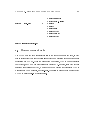
2.1 Introduction
The navigation software is a hierarchical implementation of the algorithms and functionality required to perform the tasks of vision sensing and robot navigation. It is designed
to be a highly exible and re-congurable component that can be integrated into several
dierent types of hardware platforms. To enforce both the external interfaces to hardware
and internal interfaces among sub-components, and to enable simultaneous execution of
multiple functional blocks, this software was written as an object-oriented, multi-threaded
application. The entire application was designed to work within the distributed computing
environments of several target experimental systems.
Specically, the code was written in Microsoft Visual C++ 6.0 using the Microsoft
Foundation Classes (MFC) library, under the Windows NT 4.0 operating system. The host
hardware for this sensing and navigation application is a dual Pentium PC, running at 133
MHz. Live video from a camera input is captured using a Matrox Meteor digitizer board, at
frame rates of up to 30 Hz and 24-bit color image resolutions of up to 512 x 480 pixels. In
addition, the PC has ethernet and serial communication ports to exchange data with other
computers. The video input and bi-directional network ports are the only connections to
external hardware.
29
CHAPTER 2. SOFTWARE ARCHITECTURE OVERVIEW
30
The software hierarchy is divided into two levels. The lower level is responsible for creating and executing the image processing pipeline to perform real-time image correlations.
These local image displacement measurements are then passed to the higher level of the
hierarchy. The role of the higher level is to perform the simultaneous tasks of mapping, vehicle state estimation, and navigation. The following sections describe the implementation
of each of these levels in the hierarchy.
2.2 Advanced Vision Processor (AVP) Library
The lower level of the software hierarchy is implemented as a software library known as
AVP. The AVP library was written by Rick Marks while an engineer at Teleos Research.
While AVP can perform many functions, including object tracking and stereo ranging, its
role within the navigation software is to provide the image registration capabilities described
in Chapter 3. Thus, AVP creates an image processing pipeline that is capable of correlating
the live camera image with a stored reference image. In addition, the reference image can
be stored in a buer for later retrieval and comparison. Essentially, AVP is a software
implementation of the work originally performed by Marks on specialized hardware for
his thesis research 2]. To reduce the computational requirements and satisfy the realtime constraints of the vision sensor, the maximum resolution of the digitizer board is not
utilized: the AVP input images are 8-bit grayscale, with a resolution of 256 x 240 pixels.
2.3 Sensor 0.7 Application
The higher level of the hierarchy takes the form of a multi-threaded application called
Sensor (the latest version is 0.7).1 Each thread in the application performs a distinct, welldened task that can execute at a sample rate that is independent of the other threads.
Thread synchronization and data exchange are performed through shared memory guarded
This application is called Sensor because it was originally designed as the vision sensing system. Since
then, the application has grown around this core functionality to include additional capabilities required for
robot navigation.
1
CHAPTER 2. SOFTWARE ARCHITECTURE OVERVIEW
31
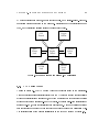
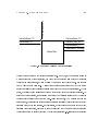
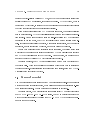
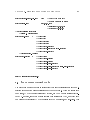
by mutual exclusion semaphores, remote procedure calls, and message-passing. Figure 2.1
graphically depicts all threads in the Sensor 0.7 application and the interactions among
them, and the following sections explain the role of each thread.
Data
Logger
Thread
GUI
Thread
Space
Frame
Link
AVP
Engine
Thread
Compute
Server
Link
AVP
OTTER
Link
Ventana
Serial
Link
Figure 2.1: Thread Diagram for Sensor 0.7 Application
2.3.1 AVP Engine Thread
As seen in Figure 2.1, the AVP Engine Thread is the central thread in the application.
This computation engine interfaces directly with the AVP library through function calls to
obtain image registration measurements, and it communicates with other threads to receive
external updates from sensors on-board the vehicle. It performs real-time calculations at
speeds of 10{30 Hz, where the digitization frame rate is 30 Hz. The computations are divided
into functional components that are executed in sequence during every calculation cycle.
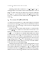
The interconnection of components is illustrated in the data ow diagram of Figure 2.2.
CHAPTER 2. SOFTWARE ARCHITECTURE OVERVIEW
CLocal
Disp
CMeas
Filter
CError
Model
CRates
CTruth
Data
CSnap
Check
32
CGlobal
Disp
CState
Filter
CError
Calc
CController
CCrossover
Detection
CCrossover
Correlation
Figure 2.2: Data Flow Diagram for AVP Engine Thread
The AVP Engine Thread is an implementation of the vision sensing system, and it can be
interfaced with other threads to create new applications. For this particular research it was
combined with interface and communication threads to enable a navigation application, but
it is an independent entity whose utility is not limited to AUV navigation. Additional components were implemented within this thread to perform navigation functions in addition
to vision sensing, as shown in the block diagram of Figure 2.2.
2.3.2 GUI Thread
The GUI Thread provides an image-based interface for the purpose of vehicle navigation.
Specically, it presents the dynamic mosaic to the user in a scrollable window, with an
`x' overlay to indicate the estimated current vehicle position within the mosaic, and an `o'
overlay to indicate the goal position. The user is able to point-and-click at a new location
within (or outside of) the mosaic to specify a new goal location. These data are then sent
to the AVP Engine Thread to control the vehicle to its new desired location.
In addition to the mosaic interface, the GUI thread provides a series of menus and dialog
boxes to manage both application execution and mosaic le storage. One of these menus
enables the user to switch the application among idle, passive sensing, and active navigation
CHAPTER 2. SOFTWARE ARCHITECTURE OVERVIEW
33
modes. Within each dialog box, graphical controls exist to modify relevant parameters for
a specic aspect of the navigation application.
Since the GUI is not as time-critical a task as real-time vehicle sensing and control,
the GUI Thread is run at a lower priority than the core AVP Engine Thread. Since each
thread executes at an independent sample rate, the GUI Thread can slow down to yield
computational power to more urgent tasks if the processor becomes overloaded.
2.3.3 Communications Link Threads
The communications link threads are a set of threads responsible for exchanging data with
external hardware or software systems. For a particular experimental setup, each of these
threads may be active or inactive, depending on whether a link to the given device is
utilized. The roles of the various communications link threads are discussed in the following
paragraphs.
ComputeServerLink This thread is enabled whenever bounded-error navigation is re-
quired. It connects via AVPNet to a MATLAB-based smoother program that performs the
optimal estimation computations for mosaic re-alignment. The smoother program executes
a MATLAB engine remotely on a Solaris UNIX compute server. AVPNet is a simple library
written to create a two-way point-to-point connection between two programs over ethernet
using the Windows Sockets API (Applications Programming Interface).
SpaceFrameLink (FlightTableLink)2 When experiments are performed on the Space
Frame, this thread connects to a network node running on a UNIX machine via AVPNet.
This network node then passes the data along to the Space Frame processor using the Network Data Delivery Service (NDDS), a low-level, high-bandwidth, peer-to-peer networking
service developed by Real-Time Innovations (RTI) for real-time communications. Sensor
The Flight Table was a previous name for the experimental apparatus now known as the Space Frame.
In the actual Sensor 0.7 code, all references are made to the Flight Table, not the Space Frame.
2
CHAPTER 2. SOFTWARE ARCHITECTURE OVERVIEW
34
data and truth measurements are received from the Space Frame, and desired position data
are sent by the application through the SpaceFrameLink.
OtterLink For experiments on OTTER, the OtterLink connects to a network node run-
ning on a UNIX machine via AVPNet, which passes the data to OTTER's on-board processor using NDDS. Since OTTER is an AUV, an automatic control system is executed by
the on-board processor. Thus, data from on-board sensors are received by the application,
and both vision sensor data and desired position data are sent back to the OTTER vehicle.
VentanaSerialLink Since no ethernet connection is available to the Ventana ROV, net-
work communication is accomplished over a serial line. The role of the VentanaSerialLink
is to provide a bi-directional serial connection directly to the Ventana ship-side processor.
Since Ventana is an ROV, it is not equipped with a complete automatic control system.
Thus, control computations are performed within the Sensor 0.7 application. Sensor data
are received from Ventana over the serial connection, and thruster commands are sent back
to the vehicle.
2.3.4 Data Logger Thread
The role of this thread is to record any relevant data in real-time for later analysis. During
each cycle of this thread, data are accessed from AVPEngineThread and saved to disk. The
Data Logger Thread has the capability to record both synchronous and asynchronous data
in real-time. Since the data logging facility is an independent thread from the primary
computations, it can run at a dierent sample rate so AVPEngineThread can maintain a
constant time interval between cycles. However, if possible, these two threads run at the
same rate, so every iteration of the computations is collected.
Chapter 3
AVP Library
This chapter presents the theoretical basis for the design decisions made in implementing
the AVP image processing library. The problem that AVP has chosen to solve is posed
in Section 3.1, while the solution AVP has chosen to implement is described in detail in
Secton 3.2. For detailed information on the actual functions contained within the AVP
library and how to integrate them into an application, refer to the AVP Manual.
3.1 Assumptions and Constraints
In deciding on the best approach for determining camera motion and scene geometry for
real-time vision-based navigation of underwater vehicles, it is necessary to discriminate
among several options based on how well they perform under the particular constraints
of this problem. For image correspondence, the specic nature of the scene determines
which method is most applicable for nding correspondence points. To extract the desired
geometric information, a simplied transformation model can be used if certain assumptions
can be made about the scene geometry and camera motion.
In order to constrain the problem and enable computationally e#cient methods for
vision sensing, the following assumptions have been made, based on the scene properties
and the capabilities of underwater vehicles:
35
CHAPTER 3. AVP LIBRARY
36
The region of operation is the near-bottom ocean oor environment. The underwater
environment has several rather unique properties, and the next section will explain
how these properties determine the proper image correspondence scheme to use.
The scene is mostly static, and it consists entirely of an approximately 2-D planar
surface within 3-D space. This assumption precludes the existence of large moving
objects or a non-stationary background, although motion of very small objects relative
to the eld of view generally are ignored by the vision sensor. Furthermore, it reduces
the required number of correspondence-pairs needed to solve for the transformation
model parameters, since the computations can take advantage of the fact that all
scene points are co-planar. The eect on the image registration of small 3-D terrain
variations around the nominal 2-D plane will be discussed in the next section.
Sequential images from a single camera are utilized for processing. This choice con-
strains the possible images sources and resultant geometric information that can be
extracted. In other words, stereo vision techniques are not used as part of this research, so only optical ow or optical displacement information may be determined.
Large motions of the underwater vehicle are only permitted in the two translational
degrees of freedom corresponding to a single plane parallel to the terrain. This assumption is justied for any vehicle using an active control system to maintain its
position and orientation. The image correlation assumes that rotations and range
changes around the nominal operating point are approximately zero. The eect of
small rotations and range changes on the image registration will be discussed in the
next section.
The vision sensor is required to perform in real-time, on hardware with limited com-
putational power.1 As a result, computational e#ciency is an important factor in
determining which methods to use for image registration.
The computational engine currently used is a dual-processor Pentium 133-Mhz system. Upgrades to
this hardware would allow more complex algorithms to be utilized, thereby increasing the measurement
accuracies and/or robustness.
1
CHAPTER 3. AVP LIBRARY
37
3.2 Solution
After considering the constraints particular to the problem of underwater vehicle navigation
along ocean oor terrain, a set of methods has been chosen to handle the process of geometric
image information extraction. The details of the texture-based image registration method
using a translational transformation model are described in this section. In addition, an
e#cient pipeline-based implementation to perform these computations on every sampled
image will be described. Finally, the process by which a mosaic is created in real-time using
these methods will be explained in detail, since this provides the basis for our advances in
mapping and state estimation.
3.2.1 Sub-Image Texture-Based Registration
In order to maximize the robustness of the measurements under arbitrary scene conditions,
a texture-based registration method is utilized. Furthermore, in order to minimize computation, subsections of each image-pair are compared. The details of this registration method
are presented in this section.
Correspondence
In the texture-based correspondence method, the images are rst convolved with a signum
of Laplacian-of-Gaussian (SLoG) lter. The Laplacian-of-Gaussian (LoG) operator, also
known as the Marr-Hildreth operator, recognizes rapid intensity variations and was originally used as part of ltering schemes for edge detection 3]. In conjunction with the signum
operator, it has several unique properties that make it ideal for use in the underwater environment.
The Gaussian lter replaces each pixel in an image with a weighted average of it and
its surrounding pixels. Convolution with the Gaussian kernel acts as a low-pass lter to
smooth the images, thus reducing the eect of noise on the image. This is particularly
useful for ocean oor imagery, since small particulate matter in the water, known as marine
snow, often adds a signicant noise component to each image.
CHAPTER 3. AVP LIBRARY
38
The next phase is the Laplacian operator, which performs a spatial second derivative
in two dimensions. It acts as a high-pass lter and has the eect of separating the image
into regions of similar texture. When taken together, the LoG acts as a band-pass lter to
reject image noise. The band frequency can be moved by adjusting the standard deviation
parameter, , of the Gaussian lter.
The nal stage of the lter is a signum function that thresholds the intensity values. Thus, it transforms the image from grayscale to black-and-white, greatly reducing
the amount of information contained within the image. Furthermore, by thresholding the
intensity, the image correspondence becomes largely insensitive to lighting variations, such
as spotlight eects or shadows. These lighting variations are quite common underwater,
since lighting must be provided articially by spotlights on-board the vehicle.
CC($ $ ) x
SC($ $ ) x
y
y
Xm Xn
i=1 j =1
Xm Xn XOR(sgnr
2
i=1 j =1
( ) ( ;$
I0 i j I1 i
x j
;$ )
] 0 ( ) sgnr2 ] 1 ( ; $
G
I
i j G
(3.1)
y
I
i
x j
; $ ))
y
(3.2)
Once each image has been ltered, the two images are correlated to establish a correspondence. Since the output of the SLoG lter contains binary pixel values, cross correlations
(Equation 3.1) become sign correlations (Equation 3.2), signicantly improving the computational e#ciency of the image correspondence. To reduce the required computation further,
the correlation stage does not compare the entire two images. Instead, a correlation window
is chosen in one image, and a search region is chosen in the second image. The correlation
window is located at the center of the live image, and the search region is located within
the reference image (see below for an explanation of the live and reference images). The
image correspondence algorithm performs the sign correlation for every possible location
of the correlation window within the search region. This produces a correlation surface,
where every point on the surface corresponds to the sign correlation value at a particular
CHAPTER 3. AVP LIBRARY
39
location of the correlation window within the search region. The highest peak on this
surface is chosen as the best match location, and the , location of this peak represents
the relative image motion.
x y
x
y
Transformation Model
Based on the fact that the robot is actively controlled to remain within a plane parallel to
the image scene, a 2-DOF translational transformation model is used to extract the relative
geometry from the image correspondence measurements. Thus, the
pixel displacement
measurements are converted simply to meters, based on the camera elds of view and the
range.
Since the robot controller is not perfect and the ocean oor not perfectly at, the rotation
and range change of the vehicle will not be identically zero. Thus, the assumptions of the
translational transformation model are violated routinely in practice, so it is important to
understand the eects of small rotations or range changes on the image correspondence.
For a non-zero yaw, range change, or 3-D terrain variation away from the nominal, the
correspondence location is shifted and the measurement condence degrades. However, the
shift in location can be removed if the correlation window in the live image is taken to be at
the center of the image. Even if there are yaw and range changes in the presence of image
translation, the correspondence of the center of the live image with the reference image will
yield an accurate measurement, since rotation and scaling of an image shift every point in
the image except the center.
The eect of non-zero roll or pitch can be handled dierently. Since roll and pitch are
equivalent to x,y translations to rst order, they oset the correspondence location without
degrading the measurement condence. This oset can be taken into account by measuring
roll and pitch with an external sensor (e.g. inclinometer) and backing out the actual x,y
translations when solving for camera position.
x y
CHAPTER 3. AVP LIBRARY
40
3.2.2 Image Processing Pipeline
For the purpose of vehicle navigation, the goal of this vision sensor is to measure image
motion while minimizing measurement drift. Therefore, an optical displacement method
will be used, which dictates the two image sources to be the live image and a previously
stored reference image. To be able to compare non-adjacent images in the mosaic, it is also
required that any image stored in the mosaic may be used as the new reference image for
future computations.
(δx, δy)
XOR
SLoG
SLoG
buffer of
stored images
reference
image
memory
live
image
memory
video
Figure 3.1: Image Processing Pipeline
To satisfy these constraints while performing the image registration computations e#ciently, an image processing pipeline has been created, as depicted graphically in Figure 3.1.
To start a cycle, the camera video is digitized and fed into the live image memory. The
image registration is then performed on the live and reference images, and the extracted
displacement sent to the next stage of the vision sensor. This entire cycle is performed at
CHAPTER 3. AVP LIBRARY
41
the frame rate of the digitizer board, subject to computational constraints. For this research, the digitizer frame rate is 30 Hz, and the computational hardware allows the image
processing pipeline to run at 10{30 Hz.
At any arbitrary time determined by the mosaicking process, a snapshot can be taken.
First, the live image is copied into the reference image memory. As soon as this transfer
occurs, this same image (now the new reference image) is copied into one of the empty slots
in the buer of stored images. Simultaneously, the image is added to the evolving mosaic
by copying it over to mosaic storage. If a loop in the vehicle path occurs, any image from
the buer may be transferred back into the reference image memory and compared to the
live image.
3.2.3 Mosaicking Process
Once the image processing pipeline has been established, the mosaicking process is relatively straightforward (Figure 3.2). Whenever a new reference image is snapped, it is added
to the evolving mosaic. By using the last registration measurement, which compared the
new reference (then live) image to the old reference image, the new snapshot can be precisely aligned in the mosaic. A new snapshot is taken whenever the overlap between the
live image and reference image reaches a pre-specied minimum area. This ensures that
there will always be su#cient overlap for image correspondence, and it produces a mosaic
whose images are taken at regular spatial intervals. On the occasion that a correspondence
measurement is deemed invalid because it falls below a given condence threshold, a new
snapshot is taken and the last valid measurement is used for alignment.
The advantage of this mosaicking process is that it enables dynamic mapping of the environment. New snapshots are added to the mosaic as they are received, thus enabling the
mosaic to grow over time as more terrain is explored. Also, it is possible to incorporate redundant measurements to improve the map accuracy. If new alignment information between
any two images in the mosaic is received, the images can easily be shifted to accommodate
the change.
CHAPTER 3. AVP LIBRARY
42
(δx, δy)
current (live)
image
reference
image
snapshots
Figure 3.2: Mosaicking Process
Chapter 4
AVP Engine Thread
The AVP Engine Thread is the main computation thread in the Sensor application. It has
the highest priority of all threads, and it is designed to run at the same sample rate as the
AVP image processing pipeline (if possible given processor constraints). The next section
describes the computational framework, followed by sections describing the functionality of
each piece in the framework. Finally, the protocol for communicating with other threads in
the application and the external Stethoscope program is described in Sections 4.6 and 4.7.
4.1 Data Flow Design and Implementation
As discussed previously in Chapter 2, the architecture for the AVP Engine Thread is described by the component-based data ow diagram of Figure 4.1. The diagram is simplied
greatly for clarity of the overall design it is decomposed into several fully detailed subdiagrams in Section 4.5. This open, modular design enables programmers to make changes
as needed to t future applications, simply by adding/deleting components and signals to
connect to the existing data ow diagram.
The data ow structure is enforced rigorously in the C++ code implementation. As
described in more detail in the following sections, the components, signals, and parameters
of the data ow diagram are implemented as class objects with the AVP Engine Thread,
and each of the components are executed in order during every iteration of the thread
43
CHAPTER 4. AVP ENGINE THREAD
CLocal
Disp
CMeas
Filter
CError
Model
CRates
CTruth
Data
CSnap
Check
44
CGlobal
Disp
CState
Filter
CError
Calc
CController
CCrossover
Detection
CCrossover
Correlation
Figure 4.1: Data Flow Diagram for AVP Engine Thread
sample loop. The AVP Engine Thread is actually an instance of the CAVPEngineThread
class, which is derived from the CWinThread class. CAVPEngineThread has messaging
capabilities that are used for inter-thread communication (Section 4.6). During every iteration of the thread's message-handling loop, the thread checks for received messages and
calls the appropriate callback function for the rst message in the queue. If the queue is
empty, the OnIdle() method is called. This OnIdle() method serves as the sample loop for
CAVPEngineThread (and all other threads in the application).
During every iteration, the OnIdle() method checks for the availability of new external
signal or parameter data that must be input into the data ow diagram. After the external
signals and parameters are updated, this method blocks until a ag is set indicating that
new measurement data is available from the AVP image processing pipeline. The Execute()
method is then called this method steps through an array that denes the order of execution
of each of the components in the data ow design, and it executes each component. Finally,
OnIdle() creates a copy of the data for buered communication with other threads.
4.1.1 Components
The boxes in the data ow diagram (Figure 4.1 represent components, each of which performs a particular computation using its input data and outputs its results for use by other
CHAPTER 4. AVP ENGINE THREAD
45
components. As stated above, the components are executed in a pre-dened order during
every iteration of the CAVPEngineThread loop. The array of components that denes the
execution order is a member variable of AVPEngineThread. All of the various components
are dierent class objects derived from the common base class CComponent. This base class
enforces the functionality required of every component: a Reset() method and an Execute()
method.
Whenever the application switches between modes, CAVPEngineThread receives a message to indicate this switch, and the OnModeChange() method is called. This method
enables and disables the appropriate components to modify the data ow diagram online
according to the desired mode. It then calls the CAVPEngineThread::Reset() method, that
in turn calls the Reset() methods of each enabled component (in execution order). The Reset() method allows each component to initialize itself and its output signals into a known
state.
The Execute() method contains code that implements the component's functionality
be perform a specic computation. The Execute() method is called once during every
iteration of the CAVPEngineThread loop. It can rely on the fact that previous components
(or external data) have supplied valid input data, and it is required to set its output data
at every iteration.
In order to strictly enforce the data ow structure, every component may only access
input/output signals and parameters that have been explicitly passed to it through its constructor. Thus, while this makes adding or modifying components more time-consuming for
the programmer, it is in a sense self-documenting, since it is possible to look at the component denition and determine which signals and parameters are used by the component
without searching through the implementation code.
4.1.2 Signals
The signals of the data ow diagram are dened as the input/output data (shown as arrows
in Figure 4.1) that are updated every iteration (i.e. synchronous data). To implement this
in code, all of the signals that appear in the data ow diagrams are grouped into a single
CHAPTER 4. AVP ENGINE THREAD
46
class, CSignals. m Signals is the CAVPEngineThread member variable of this type, which
is used as the working copy of the signals for the component computations. However,
m Signals is not used as a \global" variable within the context of CAVPEngineThread and
the CComponent-derived classes. Instead, individual signal elements within m Signals are
passed by reference to each component through its constructor when it is created on the heap
(using new ) and added to the m ComponentArray in CAVPEngineThread::InitInstance().
In this fashion, each component can use particular input signals and modify particular
output signals as needed, while CAVPEngineThread maintains a single common copy of
the data as each component modies it.
The m BueredSignals member variable of CAVPEngineThread is also of type CSignals
it is used to store a copy of the most recent signals to enable buered communication with
other threads.
4.1.3 Parameters
Parameters are dened as the input/output data (not shown in Figure 4.1) that are only
updated as needed (i.e. asynchronous data). In the more detailed diagrams of Section 4.5,
the parameters are the arrows going into or out of the top of the component boxes. Parameters are often used as reference values (e.g. the current Gaussian lter size) or event
ags (e.g. crossover detected), and thus they do not generally change after every iteration.
The parameters are implemented in code in the same fashion as signals: they are grouped
together into a single class, CParameters. m Parameters is a CAVPEngineThread member
variable, and individual parameters within m Parameters are passed by reference to the
components through their constructors.
4.1.4 Adding Components/Signals/Parameters
The code has been implemented in such a way that changes to the data ow design should
be easily transferred to code modications. Specically, components and their associated
signals and parameters can be modied or removed by changing m Component Array in
CHAPTER 4. AVP ENGINE THREAD
47
CAVPEngineThread::InitInstance(). To add a new component (or signal or parameter) to
the application code, the following procedure should prove useful. This procedure is in the
le AddingComponents.txt within the C++ source code directory.
To add new components to AVPEngine:
-----------------------------------
1)
If any input/output signals do not yet exist, add them to the CSignals class.
Also, if any of the input signals are external (i.e. they are not also output
signals of any other component): add them to the CExternalSignals class
initialize them in ExternalSignals::Initialize() add a member function to
AVPEngineThread to set them copy them from m_ExternalSignals to
m_Signals in AVPEngineThread::CheckForExternalSignalsUpdate.
2)
If any parameters do not yet exist, add them to the CParameters class.
Also,
initialize them in the CParameters constructor, CParameters::CParameters.
3)
Derive a new component class from CComponent.
4)
Declare the input/output signals and parameters by reference as member variables.
5)
Delete the existing default constructor and define a constructor with all signals
and parameters as function parameters, and initialize the member variables with
these (by reference) values in the member initialization list.
6)
In AVPEngineThread::InitInstance(), create an object of your derived CComponent class
using the new operator.
Pass to the constructor the required m_Parameters... and
m_Signals... that the component will need.
Change the call to
ComponentArray.SetSize() to reflect the new number of components.
Finally, add the
new component to the relevant modes in AVPEngineThread::OnModeChange().
7)
Override the Reset() member function of your derived CComponent class.
In this
member function, be sure to initialize all output signals and internal member
variables.
CHAPTER 4. AVP ENGINE THREAD
8)
48
Override the Execute() member function of your derived CComponent class.
In this
member function, write the code that will be executed every iteration.
4.2 System Geometry/Frame Descriptions
Before describing in detail the functionality of each of the components in the data ow diagram, the system geometry is explained in this section. The signals are named based on the
frame descriptions and the component computations are often centered around frame transformations. Therefore, this section will bridge the gap between the theoretical derivation
described in Steve Fleischer's thesis 1] and the source code implementation of the Sensor
application. While the names of variables dier between the theory and the code, there
should still be a one-to-one correspondence between many of the variables. An attempt
was made to convey the same frame information in the naming of variables in code, as is
done through subscripts and superscripts in the thesis. The following discussion on system
geometry also assumes knowledge of the mosaicking process, as described in Chapter 3 of
this manual.
Based on the mechanics of the video mosaicking process, the two fundamental frames
used to describe the system geometry are attached to the most recently stored snapshot
image and the current image. These two frames are depicted in Figure 4.2 as and ,
respectively. More precisely, the frame could be written as ( ), since it is the th
snapshot in the image chain that forms the mosaic. However, for the sake of simplicity, this
parameter is not explicitly written every time. In essence, frame represents the relevant
section of the mosaic map that is used to localize the vehicle within the map. The origin of
each frame coincides with the center of the corresponding image, and the axes are aligned
with the camera orientation. The image correlator measures the local
displacements of
the center of image (i.e. the origin of frame ) with respect to frame .
The frames in Figure 4.2 are closely related to the evolving mosaic. Figure 3.2 illustrates
the dynamic mosaic creation process, including the current image that may or may not
become a new snapshot in the image chain that forms the mosaic. Frame is attached
I
I
I k
k
I
x y
I
0
I
0
I
I
I
0
CHAPTER 4. AVP ENGINE THREAD
49
C’x
V’y
V’x
V’z
C’y
C’z
I’x
Tx
Ix
Wy
I’y
Wx
Ty
Wz
I’z
Iy
Tz
Iz
Figure 4.2: System Geometry
to the most recent snapshot, and frame is attached to the current image. When a new
image is digitized and becomes the current image, two possibilities can occur. If the current
image did not become a snapshot image in the mosaic, the frame attaches to the new
current image and the frame does not change. On the other hand, if the current image
does become part of the mosaic, the frame becomes the new frame (since the current
image has become the most recent snapshot), and the frame moves to the new current
image as before.
Two more frames are used to describe the ocean oor environment. Frame is xed in
inertial space, its origin coincides with the center of the initial image in the mosaic (i.e. the
origin of frame (0)), and its axes are aligned with the sloping ocean oor terrain. Frame
I
0
I
0
I
I
0
I
I
0
T
I
CHAPTER 4. AVP ENGINE THREAD
50
is also xed in inertial space, its origin also coincides with the center of the initial image
in the mosaic, but its axes are aligned with gravity.
To describe the vehicle and its components, two frames have been added to Figure 4.2.
Frame is aligned with the on-board camera, and it represents the camera state when
image was taken. The altimeter measures the range from the origin of (i.e. the center
of the camera) to the origin of (i.e. the center of the image). Frame , also taken at
the time corresponding to image , coincides with the vehicle center of mass and is aligned
with the vehicle body. The compass and inclinometer measure the orientation of the vehicle
frame relative to the world frame , and the pan/tilt sensors measure the orientation
of relative to .
For the descriptions to follow, all orientations are expressed in Z:Y:X ( = , , =
yaw, pitch, roll) body-xed Euler angles. To perform intermediate computations, the Euler
angles are often converted to rotation matrices.
W
C
I
0
0
C
I
0
I
V
C
0
0
V
0
0
0
W
V
0
4.3 Signal Descriptions
This section provides a brief description of every signal that appears in the AVP Engine
Thread data ow diagram. These signals are dened as member variables of the CSignals
class, which can be found in the les Signals.h and Signals.cpp. Each signal in the following
list is written in the form type name, exactly as it would appear in a variable declaration.
Any type that is not a basic type is either a class dened by MFC or a class written especially
for the purposes of this application.
CTimestamps m Timestamps The tick and calculation counts that will be used to com-
pute the sample rates for several sample loops in the system: the digitization frame
rate, the AVP calculation rate, and the AVP Engine sample rate. Units: msec
CRates m Rates The digitization frame rate, the AVP calculation rate, and the AVP
Engine sample rate after these are computed from m Timestamps. Units: Hz
CImage m LiveImage The intensity and color data for the current digitized image.
CHAPTER 4. AVP ENGINE THREAD
51
CRect m SearchRegion The region of pixels in the reference image to search for a match
with the center of the live image. The search region is centered around the point that
was the maximum likelihood match estimate in the previous iteration. Units: pixels
CRect m TrueSearchRegion m SearchRegion expanded by the size of the correlation
window (i.e. the correlation window centered around the maximum likelihood match
estimate is fully enclosed in this region). Units: pixels
CDoublePoint m ImageLocalDisp The 2-D displacement vector from the center of the
reference image ( frame) to the match location in the reference image ( frame). In
addition, spurious data has been removed from this signal in the CMeasurementFilter
component. Units: pixels
I
I
0
CDoublePoint m ImageLocalDispRaw Same as m ImageLocalDisp, except that no
measurement ltering has been performed this is the raw result from the correlation measurement. Units: pixels
double m ImageLocalDispConf The condence value of the current correlation measurement (m ImageLocalDisp), falling within the range 50%{100%. Units: percentage
CDoublePoint m ImageLocalDispVar The variances of the and components of
x
y
m ImageLocalDisp, the image local displacement vector. Units: pixels2
BOOL m DataValid A Boolean ag that is set to TRUE if the image local displace-
ment condence (m ImageLocalDispConf) is greater than the threshold value, and
otherwise set to FALSE.
BOOL m CurrentImageSnapped A Boolean ag that is set to TRUE if the current image should be taken as a \snapshot" and added to the evolving mosaic, and otherwise
set to FALSE.
double m Altimeter The latest data received directly from the altimeter (aligned with
the camera axis) on-board the vehicle. Although there is a lter to transform these
CHAPTER 4. AVP ENGINE THREAD
52
altimeter units into meters, for the case of Ventana, this raw signal is in units of
meters.
double m AltimeterVar The variance of the above data. Units: m Altimeter2
double m LOSRange CF The range from the camera ( frame) to the imaged terrain
C
0
( frame) along the optical axis of the camera ( -axis of frame). This is essentially
m Altimeter after the measurement lter has transformed units and removed spurious
data. Units: meters
I
0
z
C
0
double m LOSRange CFVar The variance of m LOSrange CF. Units: meters2
double m LOSRangeVel CF The rate of change of the range vector, m LOSRange CF.
Units: meters/sec
CPoint3D m PanTilt For Ventana, the orientation of the camera ( frame) relative to
C
0
the vehicle ( frame). Since Ventana's camera is articulated in 2-DOF in the tilt
direction, m PanTilt.x = pan angle, m PanTilt.y = shoulder angle, and m PanTilt.z
= wrist angle. To calculate the actual tilt angle for Ventana: tilt angle = m PanTilt.y
+ m PanTilt.z + 2 . This data is received directly from Ventana. Units: radians
V
0
CPoint3D m PanTiltVar The variances of each component measurement in m PanTilt.
Units: radians2
CPoint3D m VehicleAngles WF The orientation of the vehicle ( frame) relative to
V
0
the world frame, . m VehicleAngles WF.x = roll, m VehicleAngles WF.y = pitch,
m VehicleAngles WF.z = yaw. This data is received directly from the attached hardware (OTTER, Ventana, or Space Frame). Units: radians
W
CPoint3D m VehicleAngles WFVar The variances of each component measurement
in m VehicleAngles WF. Units: radians2
CPoint3D m VehicleAnglesVel WF The rate of change of each component measurement in m VehicleAngles WF. Units: radians/sec
CHAPTER 4. AVP ENGINE THREAD
53
CDoublePoint m FOV The horizontal (x) and vertical (y) elds of view of the camera
on-board the vehicle. This eld of view is measured according to the original image,
not the sub-sampled image used by AVP. Units: radians
CState m CameraState VF The 6-DOF state vector ( , , position, and roll, pitch,
x
y
z
yaw orientation in body-xed Z:Y:X Euler angles) describing the location of the camera ( frame) relative to the vehicle ( frame). Units: meters, radians
C
0
V
0
CState m CameraState VFVar The variances of the component measurements in the
vector m CameraState VF. Units: meters2 , radians2
CDoublePoint m ImageLocalDispTruth For the Space Frame, the baseline truth (ac-
cording to the Space Frame) measurement of the displacement vector from the center
of the reference image to the match location in the reference image. Units: pixels
CState m ImageState TFTruth For the Space Frame, the baseline truth 6-DOF state
of the image ( frame) relative to the terrain ( frame). Units: meters, radians
I
0
T
CState m VehicleState WFTruth For the Space Frame, the baseline truth 6-DOF state
of the vehicle ( frame) relative to the terrain ( frame). Units: meters, radians
V
0
T
CImageDeltaXY TF m ImageDeltaXY TF The local image displacement vector (
I
frame to frame) and the associated variances, expressed in terms of the terrain
frame . Units: meters, meters2
I
0
T
CState m ImageState TF The 6-DOF state of the image ( frame) relative to the terI
0
rain ( frame). Units: meters, radians
T
CStateVar m ImageState TFVar The covariance matrix of the 6-DOF state vector
m ImageState TF. Since this 6x6 matrix is symmetric, it is expressed in terms of
the upper-left (pp), upper-right(pq), and lower-right (qq) quadrants. Units: meters2 ,
meters*radians, radians2
CState m CameraState TF The 6-DOF state of the camera ( frame) relative to the
C
terrain ( frame). Units: meters, radians
T
0
CHAPTER 4. AVP ENGINE THREAD
54
CStateVar m CameraState TFVar The covariance matrix of the 6-DOF state vector
m CameraState TF. Since this 6x6 matrix is symmetric, it is expressed in terms of
the upper-left (pp), upper-right(pq), and lower-right (qq) quadrants. Units: meters2 ,
meters*radians, radians2
CState m VehicleState TF The 6-DOF state of the vehicle ( frame) relative to the
V
0
terrain ( frame). This data has also been ltered in the CStateFilter component.
Units: meters, radians
T
CState m VehicleState TFRaw The 6-DOF state of the vehicle ( frame) relative to
V
0
the terrain ( frame). Units: meters, radians
T
CDoublePoint m ImageLocalVel The rate of change of the image local displacement
vector, m ImageLocalDisp. Units: pixels/sec
CState m VehicleVel VF The 6-DOF vehicle velocity vector, expressed in terms of its
own frame, . This data has also been ltered in the CStateFilter component. Units
meters/sec, radians/sec
V
0
CState m VehicleVel VFRaw The 6-DOF vehicle velocity vector, expressed in terms
of its own frame, . Units: meters/sec, radians/sec
V
0
CDoublePoint m DesiredCameraXYPos TF The , desired position of the camera,
x
y
expressed relative to the terrain frame, . Units: meters
T
CState m DesiredVehicleState TF The 6-DOF desired state of the vehicle, expressed
relative to the terrain frame, . Units: meters, radians
T
CState m DesiredVehicleVel VF The 6-DOF desired vehicle velocity, expressed in its
own frame, . Units: meters/sec, radians/sec
V
0
CState m VehicleStateError VF The 6-DOF error vector between the desired vehicle
state (m DesiredVehicleState TF) and the actual vehicle state (m VehicleState TF),
expressed in terms of its own frame, . Units: meters, radians
V
0
CHAPTER 4. AVP ENGINE THREAD
55
CState m VehicleVelError VF The 6-DOF error vector between the desired vehicle
state (m DesiredVehicleVel VF) and the actual vehicle velocity (m VehicleVel VF),
expressed in terms of its own frame, . Units: meters/sec, radians/sec
V
0
CState m Control The 6-DOF control vector that is sent to the vehicle. The range and
units of each component are determined by the CController component. For Ventana,
CController maintains a range of 10 volts. These signals have also been ltered
through slew-rate, saturation, and deadband lters.
CState m ControlRaw The 6-DOF control vector that is output directly from the linear
controllers implemented in the CController component. The range and units of each
component are determined by the CController component. For Ventana, CController
maintains a range of 10 volts.
4.4 Parameter Descriptions
This section provides a brief description of every parameter that appears in the AVP Engine Thread data ow diagram. These parameters are dened as member variables of the
CParameters class, which can be found in the les Parameters.h and Parameters.cpp. Each
parameter in the following list is written in the form type name, exactly as it would appear
in a variable declaration. Any type that is not a basic type is either a class dened by MFC
or a class written especially for the purposes of this application.
CSize m SubImageSize The width ( ) and height ( ) of the subsampled image that is
x
y
used by AVP in its image processing pipeline and provided to the GUI. Units: pixels
CSize m FullImageSize The width ( ) and height ( ) of the original digitized image that
x
y
is used to dene a \reference" pixel, regardless of the region-of-interest (ROI) used in
subsampling. Units: pixels
CRect m CorrelationWindow The region of pixels in the live image that is compared
to all possible locations within the search region in the reference image. Units: pixels
CHAPTER 4. AVP ENGINE THREAD
56
int m GaussSigma The width of the Gaussian kernel used to smooth the images in the
ltering phase of the AVP image processing pipeline. It ranges from 0 (no smoothing)
to 10. Units: pixels
BOOL m Color A Boolean ag set to TRUE if the color data of the digitized images
should be saved for use in the mosaic and GUI, and otherwise set to FALSE for
grayscale images. The image ltering and correlation computations are only intensitybased, regardless of the value of this ag.
CMosaicData m MosaicData This parameter contains all of the image data, relative
image alignment data, and associated node graph representations of the current mosaic.
double m Threshold The threshold below which the image local displacement measure-
ments are considered invalid. This parameter is compared to m ImageLocalDispConf
at every iteration to determine the validity of the vision measurements. Units: percentage
int m AllowableDropouts The number of consecutive invalid vision measurements that
is allowed before the vehicle is assumed to be \lost" and a new reference image is
snapped. If this happens, the mosaicking process assumes the vehicle has not moved
since the last valid measurement. Since this is clearly not accurate, this severely
degrades the quality of the mosaic.
BOOL m ManualSnap A Boolean ag that is set to TRUE if the user or the application
has specied that a new image be snapped for the mosaic immediately (before reaching
the desired overlap with the reference image), and otherwise set to FALSE.
double m DesiredOverlap The desired percentage overlap in either the horizontal or
vertical directions for consecutive images in the evolving mosaic. Since the center of
the live image (and the surrounding correlation window) must lie within the reference
image for correlation to be possible, the range is between 50% (depending on
correlation window size) and 100%. Units: percentage
>
CHAPTER 4. AVP ENGINE THREAD
57
BOOL m CrossoverDetected A Boolean ag that is set to TRUE if the CCrossoverDe-
tection component has detected a possible loop in the mosaic, and otherwise set to
FALSE.
int m CrossoverImage The index of the image that is suspected of overlapping with the
current live image. The range is 0{255, given the image storage capacity allowed by
AVP.
CRect m CrossoverSearchRegion The region in the crossover image that must be
searched to match the center of the live image. The size of this region is computed
from the variances of individual image displacement measurements, in order to nd a
crossover match with probabilistic certainty. Units: pixels
BOOL m CrossoverCorrelation A Boolean ag that is set to TRUE if a successful
crossover correlation has occurred, and otherwise set to FALSE.
CMeasurementFilterParams m MeasurementFilterParams This parameter has all
of the relevant parameters for the CMeasurementFilterParams component. These
values aect the measurement lters on incoming sensor data.
CStateFilterParams m StateFilterParams This parameter contains all of the relevant
parameters for the CStateFilter component. These values aect the state lter on the
estimate of vehicle state relative to the terrain frame.
CControllerParams m ControllerParams This parameters contains all of the relevant
parameters for the CController component. These values aect the controllers and
slew-rate, saturator, and deadband lters on the control output to the vehicle.
4.5 Component Descriptions
This section provides a brief description of every component that appears in the AVP
Engine Thread data ow diagram. These component classes are all derived from the
CHAPTER 4. AVP ENGINE THREAD
58
CComponent class, and they all can be found in the les CComponents.h and CComponents.cpp. Only one instance of each component class exists in the m ComponentArray
of CAVPEngineThread, so the descriptions below are labeled according to class name.
Timestamps
Rates
RateCalculation
Figure 4.3: Data Flow Diagram for CRateCalculation
CRateCalculation This component is responsible for collecting tick counts, computing
sample times, and calculating the following rates: the AVP Digitizer frame rate, the
AVP sample rate, and the AVPEngine loop sample rate.
CLocalDisp This component interfaces directly with the AVP image processing pipeline.
After retrieving the live image, it sets up the variables required for the correlation
measurement. The image local displacement vector and its condence are then determined based on the output of the AVP function call to perform the correlation. The
component handles the cases where the previous correlation was valid or invalid, the
previous live image was a snapshot added to the mosaic, and a possible crossover was
detected during the previous iteration of the AVPEngine sample loop.
CErrorModel This component determines the data validity of the vision correlation measurement and calculates the measurement variances. To calculate the data validity, it
checks whether the vision measurement condence is above or below a given threshold. The optimal threshold to use was determined experimentally in Steve Fleischer's
CHAPTER 4. AVP ENGINE THREAD
MosaicData
CrossoverCorrelation
Color
CorrelationWindow
SubImageSize
CurrentImageSnapped
DataValid
LocalDisp
59
SearchRegion
LiveImage
TrueSearchRegion
ImageLocalDisp
ImageLocalDispConf
Figure 4.4: Data Flow Diagram for CLocalDisp
thesis to be about 63% dierent values may work better under radically dierent
conditions. Independent of the data validity, the measurement variance is calculated
using an empirical model determined through experiments on the Space Frame. The
input to this model is the measurement condence, and the outputs are the variances
on the and image local displacements.
x
y
CMeasurementFilter The measurement lter performs validity checks and removes spu-
rious data from the vision-based and altimeter measurements. (Although not implemented, lters could be added for other sensors, such as the compass and inclinometers.) In addition, this component calculates ltered velocities for these three degrees
of freedom, based on the input sensor data. This component is only enabled if the
Sensor application is connected to Ventana.
CHAPTER 4. AVP ENGINE THREAD
CrossoverCorrelation
FullImageSize
ManualSnap
AllowableDropouts
Threshold
CorrelationWindow
GaussSigma
ImageLocalDisp
ImageLocalDispConf
60
ImageLocalDispVar
DataValid
Timestamps
LOSRange_CF
FOV
ErrorModel
Figure 4.5: Data Flow Diagram for CErrorModel
CTruthData Using baseline truth measurements (m VehicleState WFTruth) from the
Space Frame, this component calculates derived quantities (m ImageState TFTruth
and m ImageLocalDispTruth) that are used as truth for comparison with corresponding measurements derived from the vision data and other sensor data. This component
is only enabled if connected to the Space Frame.
CGlobalDisplacement This component performs the frame transformation that combine
the input sensor data into estimates of the image, camera, and vehicle states. For
information on the derivation of these equations, refer to Steve Fleischer's thesis 1].
CStateFilter This state lter has the ability to modify the estimate of vehicle state relative
to the terrain frame, m VehicleState TF, and the estimate of vehicle velocity relative
to the vehicle frame, m VehicleVel VF. Currently, no ltering is performed in this
component.
CHAPTER 4. AVP ENGINE THREAD
ImageLocalDisp
PanTilt
PanTiltVar
VehicleAngles_WF
VehicleAngles_WFVar
MeasurementFilterParams
Altimeter
AltimeterVar
61
MeasurementFilter
ImageLocalDisp
ImageLocalDispRaw
LOSRange_CF
LOSRange_CFVar
ImageLocalVel
Timestamps
DataValid
LOSRangeVel_CF
VehicleAnglesVel_WF
CurrentImageSnapped
CameraState_VF
CameraState_VFVar
Figure 4.6: Data Flow Diagram for CMeasurementFilter
CCrossoverDetection The responsibility of this component is to determine if it is prob-
able that the mosaic has just crossed over itself. First, the minimum measurement
variance between the live image and all other images in the mosaic are computed,
since this is needed for the detection algorithm. Then, the location of the live image is compared to the locations of all other images in the mosaic to determine if a
crossover may have occurred. Only previous image displacement measurements and
variances are used no new (computationally expensive) correlations occur.
CSnapCheck This component checks to see if a snapshot of the live image should be
taken and added to the evolving mosaic. If the minimum desired overlap between
the live and reference images has been reached, or a manual snap has been ordered by either the CErrorModel component (due to data validity problems), the
CCrossoverDetection component (due to possible crossover), or the user, the CMosaicData::SnapNewImage() method is called to snap the live image and record all of
the relevant data.
CHAPTER 4. AVP ENGINE THREAD
CameraState_VF
MosaicData
CrossoverImage
CrossoverCorrelation
FullImageSize
VehicleState_WFTruth
62
ImageState_TFTruth
ImageLocalDispTruth
TruthData
Figure 4.7: Data Flow Diagram for CTruthData
CCrossoverCorrelation If the CCrossoverDetection component indicates that a loop in
the mosaic may have occurred, this component modies the image processing pipeline
to compare the live image with the crossover image. In the next iteration, this component interprets and records the results of the crossover correlation, and restores the
pipeline to normal operation.
CErrorCalculation This component produces a vehicle state error vector by calculating
the dierence between the desired and actual vehicle states. Similarly, it produces
a vehicle velocity error vector by calculating the dierence between the desired and
actual vehicle velocities.
CController This component calculates the control values that are sent to the vehicle actuators to perform the station-keeping, mosaicking, and navigation tasks. Specically,
it implements a dierent controller for each DOF, using the vehicle state and velocity
CHAPTER 4. AVP ENGINE THREAD
LOSRange_CF
LOSRange_CFVar
FOV
CameraState_VF
CameraState_VFVar
CrossoverImage
VehicleAngles_WF
VehicleAngles_WFVar
CrossoverCorrelation
MosaicData
FullImagesize
ImageLocalDisp
ImageLocalDispVar
63
ImageDeltaXY_TF
ImageState_TF
ImageState_TFVar
CameraState_TF
GlobalDisplacement
ImageLocalVel
LOSRangeVel_CF
CameraState_TFVar
VehicleState_TF
VehicleVel_VF
VehicleAnglesVel_WF
Figure 4.8: Data Flow Diagram for CGlobalDisplacement
error vectors as inputs. Currently, only the , , and translational DOF are used.
Each independent control signal is sent through a slew-rate, saturator, and deadband
lter before it is sent to the vehicle actuators.
x
y
z
4.6 Inter-Thread Communication
As evidenced by the structure of Figure 2.1, the CAVPEngineThread is the central thread
in the Sensor application. It is the repository for all data, and all other threads require
access to this data. Two dierent strategies are used to communicate among threads:
message-passing, and remote function calls.
Message-passing enables the reliable, asynchronous ow of data between threads. All
messages that are sent are received (even two dierent messages of the same message type to
the same thread), but it is not guaranteed that they will arrive at the destination at a given
time (i.e. before the next iterations have completed). It is described in Section 4.6.1.
Remote function calls are used for idempotent synchronous data ow between threads.
Given a pointer to an external thread, it is possible to call one of the thread's methods,
n
CHAPTER 4. AVP ENGINE THREAD
StateFilterParams
VehicleState_TF
VehicleVel_VF
64
VehicleState_TF
Vehicle_Vel_VF
VehicleState_TF
VEhicleVel_VFRaw
StateFilter
Figure 4.9: Data Flow Diagram for CStateFilter
thereby giving access to the external thread's data. However, if the external thread is
modifying its data at every iteration, the data must be protected from reading by external
threads at improper times, and from writing by more than one thread at once. Semaphores
can be used to accomplish this. A client thread calls a server thread method that blocks
until the external thread triggers a certain event (such as the end of an iteration). At this
point, the client thread calls server thread methods that get or set certain variables. To
enforce mutual exclusion, these access methods lock the variables against use by the server
thread until the client has get/set the data. Using this model, CAVPEngineThread is the
server thread, while all other threads in the application are client threads that pend on every
iteration through the sample loop. In this fashion, other threads can get/set data at every
iteration (synchronously), although it is not guaranteed that the other threads will nish
their tasks in time to receive data from the very next iteration (i.e. reliable communication
CHAPTER 4. AVP ENGINE THREAD
65
ImageDeltaXY_TF
ImageState_TF
Timestamps
CrossoverSearchRegion
CrossoverImage
CrossoverDetected
FOV
ManualSnap
MosaicData
CorrelationWindow
SubImageSize
FullImageSize
LOSRange_CF
CrossoverDetection
Figure 4.10: Data Flow Diagram for CCrossoverDetection
is not guaranteed). Sections 4.6.2 and 4.6.3 describe how to access signal and parameter
data from CAVPEngineThread.
4.6.1 Thread Messaging
Message-passing is accomplished using the existing Windows messaging scheme that is inherited from the CWinThread class. Under Windows messaging, given a pointer to an external thread, a message can be sent to that thread using CWinThread::PostThreadMessage().
As part of a thread's message-handling loop, received messages are dispatched to the appropriate callback function based on message tables dened during compile time. Many
user-dened message have been created for this purpose. In addition, new messages (and
message handler functions) can be created the following procedure may prove useful to
programmers who wish to add messages:
To add new thread message handler functions to one of the CWinThread-derived classes:
CHAPTER 4. AVP ENGINE THREAD
66
ImageState_TF
ImageState_TFVar
ImageLocalDispTruth
ImageLocalDisp
LOSRange_CF
LOSRange_CFVar
ImageLocalDispVar
FOV
ImageDeltaXY_TF
ImageState_TFTruth
VehicleState_WFTruth
CameraState_TF
MosaicData
FullImageSize
ManualSnap
DesiredOverlap
LiveImage
Timestamps
CurrentImageSnapped
SnapCheck
CameraState_TFVar
Figure 4.11: Data Flow Diagram for CSnapCheck
-------------------------------------------------------------------------------------
1)
If not already defined, define the thread message in Defaults.h
2)
Add the ON_THREAD_MESSAGE macro to the thread's message map in *.cpp.
3) Add the afx_msg function declaration within the class declaration in *.h.
4)
Define the function in *.cpp.
4.6.2 External Access for Signals
If an external thread wishes to get signal data from CAVPEngineThread, the rst step
is to call the WaitForUpdatedSignals() method. This call will block until the current
CAVPEngineThread iteration has completed. At this point, the working copy of the signals, m Signals, is copied into m BueredSignals, so that external threads have a static
access point until the next iteration. Once the WaitForUpdatedSignals() method returns,
the external thread can call the appropriate Get*() method to retrieve the latest signal
CHAPTER 4. AVP ENGINE THREAD
ImageLocalDisp
ImgeLocalDispVar
ImageLocalDispConf
ImageDeltaXY_TF
CrossoverCorrelation
CrossoverSearchRegion
CrossoverImage
CrossoverDetected
CorrrelationWindow
MosaicData
SearchRegion
TrueSearchRegion
67
SearchRegion
TrueSearchRegion
CrossoverCorrelation
DataValid
Figure 4.12: Data Flow Diagram for CCrossoverCorrelation
values from CAVPEngineThread, and this method takes care of resource locking to ensure
mutual exclusion.
Within CAVPEngineThread, signals that may be set from an external thread are part
of the CExternalSignals class. To set any of these signals, an external thread simply calls
the appropriate Set*() method, and this method takes care of resource locking to ensure
mutual exclusion. At the beginning of every CAVPEngineThread iteration, a check is made
to determine if any of these external signals have been set since the last iteration. If so, all
of the external signals (m ExternalSignals) are copied into their counterparts in the working
copy of all signals, m Signals. The following procedure explains how to add new external
signals as needed:
To add a new external signal to AVPEngineThread:
---------------------------------------------------
CHAPTER 4. AVP ENGINE THREAD
68
DesiredCameraXYPos_TF
DesiredVehicleState_TF
VehicleState_TF
DesiredVehicleVel_VF
VehicleStateError_VF
VehicleVelError_VF
VehicleVel_VF
CameraState_TF
ErrorCalculation
CameraState_VF
Figure 4.13: Data Flow Diagram for CErrorCalculation
1)
Follow procedure to add new member variable to CSignals, if not already present.
2)
Add new member variable to CExternalSignals.
3)
Initialize the member variable in CExternalSignals::Initialize().
4)
Copy external signal into appropriate signal or do required processing in
CAVPEngineThread::CheckForExternalSignalsUpdate().
5)
Add a Get*() method to set the new member variables
4.6.3 External Access for Parameters
Within CAVPEngineThread, parameters that may be accessed (read or write) from an
external thread are part of the CExternalParameters class. To set any of these external parameters, an external thread sends a message to CAVPEngineThread. A userdened message has been created for each external parameter. At the beginning of every CAVPEngineThread iteration, a check is made to determine if any of these external
parameters have been set since the last iteration. If so, all of the external parameters
CHAPTER 4. AVP ENGINE THREAD
69
ControllerParams
VehicleStateError_VF
VehicleVelError_VF
Control
ControlRaw
Timestamps
Controller
Figure 4.14: Data Flow Diagram for CController
(m ExternalParameters) are copied into their counterparts in the working copy of all parameters, m Parameters. Thus, parameter changes are reliable, but not necessarily synchronous.
The following procedure explains how to add new external parameters as needed:
To add a new external parameter to AVPEngineThread:
---------------------------------------------------
1)
Follow procedure to add new member variable to CParameters, if not already present.
2)
Add new member variable to CExternalParameters.
3)
Initialize the member variable in CExternalParameters::Initialize().
4)
Copy external parameter into appropriate parameter or do required processing in
CAVPEngineThread::CheckForExternalParametersUpdate().
CHAPTER 4. AVP ENGINE THREAD
5)
Add thread messages to get/set the new member variables
6)
Add thread message post to CAVPEngineThread::OnGetAllParams()
7)
Add thread message handler to CAVPEngineThread to set values sent from GUI
8)
Add thread message handler to CSensorApp to get current values and show in GUI
70
4.7 Stethoscope
As explained in Section 1.6, the external Stethoscope program can be used to view real-time
plots of internal variables from CAVPEngineThread. Upon initialization, the InstallSignalsForScope() method is called to export all of the necessary variables for Stethoscope access.
At the end of every iteration in the OnIdle() loop, the ScopeCollectSignals() library function
is called to take a snapshot of all of the installed variables and send them to any connected
Stethoscope clients. To export any member variable in CAVPEngineThread to Stethoscope, one only needs to add new lines to the CAVPEngineThread::InstallSignalsForScope()
method for the additional variables the data collection mechanism is already in place.
Chapter 5
GUI Thread
The GUI thread, which is actually an instance of the CSensorApp class, is the original
thread created upon application startup. During the CSensorApp initialization, all other
threads are spawned from this one. For the most part, the GUI has been described fully in
the User's Guide (Chapter 1). This chapter explains how CSensorApp follows the Microsoft
Foundation Classes (MFC) philosophy for creating applications. Once a solid understanding
of MFC is achieved, it will become evident how the CSensorApp code ts into the MFC
framework.
As with CAVPEngineThread, CSensorApp execution consists of a message-handling
loop that dispatches messages and calls the OnIdle() method when no messages are present
in the queue. The goal of the CSensorApp::OnIdle() method is to access data from every
iteration of CAVPEngineThread (if possible) and provide that data to the appropriate documents and dialog boxes. Specically, the CAVPEngineThread::WaitForUpdatedSignals()
method is called to block until new data is ready. Upon return, the CSensorApp thread calls
several CAVPEngineThread::Get*() methods are called, and the returned data is stored in
the active mosaic document and in the output display dialog class (COutputDisplayDlg).
The data storage, data display, and user input functions for CSensorApp are accomplished
by various documents, views, and dialog boxes. These will be discussed in the following
sections.
71
CHAPTER 5. GUI THREAD
72
5.1 Documents
Within the MFC framework, all application data is stored in the form of documents. The
Sensor GUI has a multiple document interface (MDI) in other words, there is more than
one type of document (data) that it can handle. The following sections describe the two
types of documents: DIB and Mosaic.
5.1.1 DIB Document
The DIB document stores images in the form of Device-Independent Bitmaps (DIB). The
DIB document is actually a model document for the Mosaic document that was taken from
an example in the MFC documentation. This example application was used as a baseline for
building the Sensor application with Mosaic document support, so DIB document support
is actually a by-product of the baseline code. However, it does provide the ability to view
individual images within the mosaic, or a mosaic exported into a single DIB image, without
resorting to external programs.
5.1.2 Mosaic Document
The Mosaic document (CMosaicDoc) reproduces the evolving mosaic that is created during
execution of CAVPEngineThread. Snapshot images are received from CAVPEngineThread
and stored as DIB's within the Mosaic document, along with relevant image alignment
data. The image alignment data is actually stored in two dierent versions: uncorrected
and corrected. The uncorrected data is purely pixel-based it represents the state-of-the-art
in mosaics before Steve Fleischer's thesis. The corrected data has incorporated both data
from sensors other than vision and knowledge of the relationships between various frames of
reference, in order to provide a more accurate (and global) mosaic alignment. Furthermore,
the corrected data is updated when a successful crossover correlation occurs and when a
mosaic re-alignment is completed, while the uncorrected data never changes from the initial
image local displacement measurements. (Warning: There are several bugs in storing and
CHAPTER 5. GUI THREAD
73
exporting uncorrected data and mosaics created from uncorrected data. Some of these bugs
have been xed, some have not, so it is recommended these be used with caution.)
The Mosaic document data can also be stored to disk via an archive (CArchive), consisting of a series of DIB les and a binary *.mos le that contains all of the non-image
data from the document. Both storage and retrieval of a Mosaic document from disk is
achieved through the CMosaicDoc::Serialize() method for more information, see the MFC
documentation on archives and serialization.
As mentioned in Chapter 1, both the uncorrected and corrected data from the Mosaic
document can be exported. The data can either be exported as an ASCII le containing
a line of data for each image, or the mosaic corresponding to the data can be exported
into a single DIB le. For details on this process, see the CMosaicDoc methods: OnExportUncorrectedMosaic(), OnExportUncorrectedData(), OnExportCorrectedMosaic(), and
OnExportCorrectedData().
5.2 Views
Within the MFC framework, each document class has an associated view class. The view
class is responsible for displaying the document's data within the GUI. For the case of
the Sensor application, the classes CDIBView and CMosaicView correspond to the CDIBDoc and CMosaicDoc classes, respectively. Within these two view classes, the OnDraw()
method is responsible for drawing in the document window. In CMosaicView::OnDraw(),
each individual image is painted on-screen in its proper location to form the mosaic, and if
the Mosaic document is currently active, graphic overlays are drawn indicating the desired
vehicle position, current vehicle position, and uncertainty in the current position. Displaying graphics under Windows and MFC is a complex proposition in addition to the
standard documentation, the le NotesOnDrawing.txt in the Sensor source code directory
may provide useful hints on various aspects of this process.
CHAPTER 5. GUI THREAD
74
5.3 Dialog Boxes
The following dialog box classes are used to implement the dialog boxes that can be called
from the Sensor GUI menus:
CImageAcquisitionDlg
CImageProcessingDlg
CMappingNavigationDlg
CSerialPortDataDlg
CMeasurementFilterParametersDlg
CControllerParametersDlg
COutputDisplayDlg
The class denitions and implementations can be found in the les Dialogs.h and Dialogs.cpp. As part of the dialog box creation process, each one of these classes is instanced
in CSensorApp::InitInstance(). The graphical dialog boxes were implemented using the Microsoft Visual Studio resource editor and then connected to their associated classes using
the Class Wizard. The transfer of data between the on-screen dialog box and the class
object is accomplished using dialog data exchange (DDX) concepts from MFC for more
information, see the MFC documentation. Complete explanations of the purpose of every
control within every dialog box has already been given in the User's Manual (Chapter 1).
Chapter 6
Communications Link Threads
To communicate with both external programs (i.e. a compute server) and external hardware
(i.e. Space Frame, OTTER, Ventana) without interrupting the main CAVPEngineThread
computation loop, several threads have been created, each of which is dedicated to providing
a communications link to a remote resource. Since these threads are concerned primarily
with exchanging data with CAVPEngineThread, as shown in Figure 2.1, they will either
call the blocking method CAVPEngineThread::WaitForUpdatedSignals() or simply remain
idle until a message is received from CAVPEngineThread.
This chapter describes the operation of each of these communication link threads. Three
of these threads, ComputeServerLink, SpaceFrameLink (FlightTableLink), and OTTERLink, communicate over ethernet using the Windows sockets protocol, and they are all
derived from the base class AVPNet. The fourth thread, VentanaSerialLink, communicates via serial link. The following sections describe the AVPNet base class and all four
communication link threads.
6.1 AVPNet
The CAVPNetThread class is an object-oriented implementation of the AVPNet socket
communications library originally created as an add-on to AVP by Rick Marks. For more
information, see the AVP/AVPNet documentation. The les AVPNet.h and AVPNet.cpp
75
CHAPTER 6. COMMUNICATIONS LINK THREADS
76
contain the object-oriented version of AVPNet, and they can be incorporated cleanly into
entirely dierent MFC applications, independent of Sensor. CAVPNetThread, which is
derived from CWinThread, is designed to be a base class for communication thread classes
that wish to inherit sockets communications functionality.
When a thread class derived from CAVPNetThread is spawned, the Sensor application
acts as a sockets server. CAVPNetThread::InitInstance() opens a port to listen for connection requests. When a remote program using the client-side version of AVPNet requests a
connection on the same port, the CAVPNetThread::Accept() method is called automatically. If there is no client already connected, a connection is established, and two archives
are created, one for reading from the socket, and one for writing to the socket.
To send data messages over the established socket connection, the derived thread class
must build up the message in the local buer using the CAVPNetThread::avpnetMsgStart()
and CAVPNetThread::avpnetMsgAdd*() methods. When complete, the message can be
sent over the socket by calling CAVPNetThread::avpnetMsgSend().
To receive messages, the CAVPNetThread::Receive() method must be overridden by
the derived class. This method is called automatically whenever new data is available on
the incoming socket. Its responsibility is to parse incoming messages, using the CAVPNetThread::avpnetMsgExtract*() methods.
6.2 ComputeServerLink
The ComputeServerLink is an instance of the CComputeServerLink class. It communicates
with the remote compute server program, which performs smoother computations to re-align
the mosaic after crossover. The compute server code is listed in Section 8.1.
To perform its task, CComputeServerLink remains idle until CAVPEngineThread sends
it a COMPUTE SERVER UPLOAD DATA message. The OnComputeServerUploadData()
method handles this message by building the DATA UPLOAD AVPNet message and sending it to the compute server.
CHAPTER 6. COMMUNICATIONS LINK THREADS
77
Concurrently, while this thread is waiting for COMPUTE SERVER UPLOAD DATA
messages, its Receive() method is called whenever a message is received from the compute
server. The Receive() method checks the message token to make sure the message token
is DATA DOWNLOAD, then extracts the improved mosaic re-alignment data and sends
it back to CAVPEngineThread via thread message to improve the self-consistency of the
mosaic map.
6.3 SpaceFrameLink (FlightTableLink)
The SpaceFrameLink is an instance of the CFlightTableLink class, and it communicates
with the Space Frame hardware. (The Flight Table is the former name of the piece of
equipment now known as the Space Frame. At the time this code was written, it was still
known as the Flight Table.)
To perform its task, CFlightTableLink remains idle until CAVPEngineThread sends
a DESIRED POS UPDATE message to move the endpoint of the Space Frame to a new
location. The OnDesiredPosUpdate() method handles this thread message by building the
MODE DATA AVPNet message with the appropriate desired position data and sending
it to the Space Frame network node. The Space Frame network node is an intermediary
program that converts AVPNet data from the Sensor application into NDDS data that is
sent directly to the Space Frame. Section 8.2 provides code for the Space Frame network
node. In addition, whenever a MODE CHANGE message is received, the OnModeChange()
handler function resets the perceived origin of the Space Frame to maintain consistency
between the Space Frame and Sensor reference frames.
Concurrently, while this thread is waiting for thread messages, its Receive() method is
called whenever a message is received from the Space Frame network node. The Receive()
method checks the message token to make sure it is a TRUTH DATA message, then extracts
the measurement data taken by the high-resolution motor encoders on the Space Frame, and
transforms them into the proper frame. These sensor data serve as truth measurements to
CHAPTER 6. COMMUNICATIONS LINK THREADS
78
evaluate the performance of the Sensor application, so they are sent to CAVPEngineThread
via the relevant Set*() methods to be stored and sent along to the GUI.
6.4 OtterLink
The OTTERLink is an instance of the COTTERLink class, and it communicates with the
OTTER AUV. To perform its task, COTTERLink retrieves the current vehicle state by calling CAVPEngineThread::GetVehicleState TF() from the OnIdle() method. The OnIdle()
method then builds the PSEUDO SHARPS DATA AVPNet message and sends it to the
OTTER network node. To use the vision-based vehicle state estimates from Sensor instead
of SHARPS positioning data, the vehicle state data masquerades as SHARPS data from
OTTER's perspective. The OTTER network node is an intermediary program that converts
AVPNet data from the Sensor application into NDDS data that is sent directly to OTTER.
Also, whenever a DESIRED POS UPDATE message is received from CAVPEngineThread
to move OTTER to a new location, the OnDesiredPosUpdate() method handles this message by building the DESIRED POS DATA AVPNet message with the appropriate desired position data and sending it to the OTTER network node. In addition, whenever a
MODE CHANGE message is received, the OnModeChange() handler function resets the
heading oset to maintain consistency between the OTTER and Sensor reference frames.
Concurrently, while this thread is waiting for thread messages, its Receive() method
is called whenever a message is received from the OTTER network node. The Receive()
method checks the message token to make sure it is a OTTER STATE DATA message,
then extracts the vehicle sensor measurements and sends them to CAVPEngineThread via
the relevant Set*() methods.
CHAPTER 6. COMMUNICATIONS LINK THREADS
79
6.5 VentanaSerialLink
The VentanaSerialLink is an instance of the CVentanaSerialLink class, and it communicates
with the Ventana ROV. CVentanaSerialLink is setup dierently than the other communication thread classes, because the network connection to Ventana is a serial line. The
InitInstance() method initialize the serial port and sets up CRC error-checking, since Ventana uses CRC.
In addition, the InitInstance() method starts a worker thread, ReadSerialPort(), to
continuously read the serial port. A worker thread is a single function running independently, which does not have any Windows messaging capabilities. The ReadSerialPort()
thread performs overlapped I/O to minimize the overhead of continuously reading the serial port. Whenever this thread reads a full record into its buer, it calls CVentanaSerialLink::ParseDataRecord() to extract the Ventana sensor data. This method extracts the
Ventana sensor data and sends it to CAVPEngineThread by calling the appropriate Set*()
methods. Also, whenever the MODE CHANGE message is received by the CVentanaSerialLink thread, the heading oset is reset to maintain consistency between the Ventana and
Sensor reference frames.
To access the control data for transmission to Ventana's thrusters, the remote method
CAVPEngineThread::WaitForUpdatedSignals() is called from within the OnIdle() method.
Once this blocking call returns, the control values are read using the remote method
CAVPEngineThread::GetControl() and the WriteSerialPort() method is called. The WriteSerialPort() method performs an overlapping write, including CRC, to optimize performance.
Chapter 7
Data Logger Thread
Data logging is accomplished by CDataLoggerThread, a relatively simple thread class derived from CWinThread. Data logging is enabled and disabled by the START DATA LOG
and STOP DATA LOG thread messages, which are sent from the GUI thread to CDataLoggerThread. The message handler methods OnStartDataLog() and OnStopDataLog()
open and close the data log les, respectively.
Every time a data log is opened, two les are actually opened for recording data. The
rst le is a synchronous data log. In the CDataLoggerThread::OnIdle() method, this
thread attempts to block on every iteration of CAVPEngineThread, and it collects data
using the CAVPEngineThread::Get*() methods and writes the data to the synchronous
data log. This thread is allowed to run at a slower sample rate than CAVPEngineThread,
although this would require the data logging to skip samples and thus lose some data.
Section 7.1 provides a list of all data recorded into the synchronous data log.
The second le opened is an asynchronous data log. This le records parameters
that change periodically, but at rates much slower than the CAVPEngineThread sample
rate. As part of the CDataLoggerThread::OnIdle() method, data is written to the asynchronous log only if the m WriteParamters ag is enabled. The following events cause the
m WriteParameters ag to be enabled: a data log is opened, a MODE CHANGE message
80
CHAPTER 7. DATA LOGGER THREAD
81
is received, a new MEASUREMENT FILTER PARAM message is received, or a new CONTROLLER PARAM message is received. Section 7.2 provides a list of all data recorded
periodically into the asynchronous data log.
7.1 Synchronous Data Log
Currently, the synchronous data log le records the following at every time step in the main
CAVPEngineThread computation loop:
pVentanaSerialLink; m TeleosON
>
timestamps.m TickCount
m SensorMode
current image snapped
image local disp conf
data valid
image local disp truth.x, .y
image local disp.x, .y
altitude
vehicle angles wf.x, .y, .z
image state tf truth.x, .y, .z
image state tf.x, .y, .z
image state tf var.pp0]0], .pp1]1]
vehicle state wf truth.x, .y, .z
vehicle state tf.x, .y, .z
CHAPTER 7. DATA LOGGER THREAD
desired vehicle state tf.x, .y, .z
vehicle state error vf.x, .y, .z
vehicle vel vf.x, .y, .z
vehicle vel error vf.x, .y, .z
control raw.x, .y, .z
control.x, .y, .z
slew rate enabledX AXIS], Y AXIS], Z AXIS]
saturator enabledX AXIS], Y AXIS], Z AXIS]
deadband enabledX AXIS], Y AXIS], Z AXIS]
pVentanaSerialLink; m Port/Stbd/Lateral/VerticalThrust
>
7.2 Asynchronous Data Log
Currently, the asynchronous data log records the following:
timestamps.m TickCount
m MeasurementFilterParams.m AltitudeScale, .m AltitudeOset
m MeasurementFilterParams.m DeadzoneSize
m MeasurementFilterParams.m VelFilterCuto
m ControllerParams.m ControlModeX AXIS], Y AXIS], Z AXIS]
m ControllerParams.m Kp.x, .y, .z
m ControllerParams.m Kd.x, .y, .z
m ControllerParams.m Ki.x, .y, .z
82
CHAPTER 7. DATA LOGGER THREAD
83
m ControllerParams.m Kl.x, .y, .z
m ControllerParams.m LeadPole.x, .y,.z
m ControllerParams.m LeadZero.x, .y, .z
m ControllerParams.m Ksm.x, .y,.z
m ControllerParams.m M.x, .y, .z
m ControllerParams.m Phi.x, .y, .z
m ControllerParams.m lambda.x, .y, .z
m ControllerParams.m SlewRate
m ControllerParams.m SatLimit
m ControllerParams.m DeadBand
pVentanaSerialLink; m SonyCameraTilt, ; m SonyCameraShoulder
>
>
Chapter 8
Distributed Software Components
This chapter provides brief descriptions and code listings for three external software components that are part of the distributed system used during experiments: the smoother, the
Space Frame network node, and the OTTER network node.
8.1 Smoother
The smoother, otherwise known as the compute server, is a C program that runs on a
Sun UNIX workstation. This software component performs the intensive computations
necessary to optimally re-align the mosaic after a crossover correlation has occurred. To
accomplish this, the program receives input via AVPNet from Sensor, calls a MATLAB
engine to perform the matrix manipulations, and returns the results via AVPNet. The
following is a le listing for the smoother program:
--- compute_server_link.cc ---
#include <stdio.h>
#include <stdlib.h>
#include "NDDS.h"
#include "nddstypes/CSMatNdds.h"
/* #include "CSMatNdds.h" */
#include "avpnetC.h"
84
CHAPTER 8. DISTRIBUTED SOFTWARE COMPONENTS
#include "ComputeServer.h"
#include "engine.h"
/* global definitions */
#define BUFFER_LENGTH
2000
/* global variables */
Engine *ep
char bufferBUFFER_LENGTH]
char command_string256]
/* forward function declarations */
void ReceiveMessages()
int main(int argc, char *argv])
{
/* Initialize MATLAB engine */
if (!(ep = engOpen("\0"))) {
printf("Can't start MATLAB engine\n")
exit(-1)
}
else {
printf("Started MATLAB engine successfully\n")
}
engOutputBuffer(ep, buffer, BUFFER_LENGTH)
/* Initialize AVPnet network interface to AVP PC */
avpnetCInitialize(SENSOR_HOST, COMPUTE_SERVER_LINK_PORT) /* client mode */
if (!avpnetCOpenConnection()) {
printf("Error in attempting connection to AVPnet server.\n")
return (1)
}
else {
85
CHAPTER 8. DISTRIBUTED SOFTWARE COMPONENTS
printf("Connection to AVPnet server successful.\n")
}
while (1) {
/* NddsConsumerPoll(itemConsumer) Only needed if NDDS_POLLED */
/* We sleep only to kill time.
Nothing need be done here
for an NDDS_IMMEDIATE consumer. */
/*printf("Sleeping for %f sec...\n", deadline)
NddsUtilitySleep(deadline)*/
NddsUtilitySleep(0.02)
ReceiveMessages()
}
engClose(ep)
return (0)
}
void ReceiveMessages()
{
int token, head, tail, i, crossover_update
unsigned int data
double delta_state2], delta_state_var2]2]
static int index, crossovers
int meas
mxArray *xhat = NULL, *Phat = NULL
double *x_data, *P_data
if (avpnetCMsgAvailable()) {
avpnetCMsgRead(&token)
switch (token) {
case DATA_UPLOAD:
printf("New DATA_UPLOAD received\n")
86
CHAPTER 8. DISTRIBUTED SOFTWARE COMPONENTS
data = avpnetCMsgExtractLong()
head = (int) data
data = avpnetCMsgExtractLong()
tail = (int) data
data = avpnetCMsgExtractLong()
delta_state0] = ((double) ((int) data)) / 1e4
data = avpnetCMsgExtractLong()
delta_state1] = ((double) ((int) data)) / 1e4
data = avpnetCMsgExtractLong()
delta_state_var0]0] = ((double) ((int) data)) / 1e8
data = avpnetCMsgExtractLong()
delta_state_var0]1] = ((double) ((int) data)) / 1e8
delta_state_var1]0] = delta_state_var0]1]
data = avpnetCMsgExtractLong()
delta_state_var1]1] = ((double) ((int) data)) / 1e8
if ((head == 0) && (tail == 0)) {
engEvalString(ep, "clear all")
index = 0
crossovers = 0
}
else {
if (tail == (index+1)) {
/* new image update */
printf("\tNew image update\n")
crossover_update = FALSE
if ((tail-head) != 1) {
printf("Problem: new image, but head and tail are not adjacent\n")
}
index++
meas = index + crossovers
if (index == 1) {
sprintf(command_string, "C = zeros(2,2)")
engEvalString(ep, command_string)
printf("%s\n", buffer)
}
else {
87
CHAPTER 8. DISTRIBUTED SOFTWARE COMPONENTS
sprintf(command_string, "C = C zeros(%i,2) zeros(2,%i)]",
2*(meas-1), 2*index)
engEvalString(ep, command_string)
printf("%s\n", buffer)
}
}
else {
/* crossover update */
printf("\tCrossover update\n")
crossover_update = TRUE
crossovers++
meas = index + crossovers
sprintf(command_string, "C = C zeros(2,%i)]",
2*index)
engEvalString(ep, command_string)
printf("%s\n", buffer)
}
sprintf(command_string, "C(%i:%i,%i:%i) = eye(2)",
2*meas-1, 2*meas, 2*tail-1, 2*tail)
engEvalString(ep, command_string)
printf("%s\n", buffer)
if (head != 0) {
/* if head = 0, no entries are needed */
sprintf(command_string, "C(%i:%i,%i:%i) = -eye(2)",
2*meas-1, 2*meas, 2*head-1, 2*head)
engEvalString(ep, command_string)
printf("%s\n", buffer)
}
if (index == 1) {
sprintf(command_string, "z = %f %f]",
delta_state0], delta_state1])
engEvalString(ep, command_string)
printf("%s\n", buffer)
sprintf(command_string, "V = zeros(2,2)")
engEvalString(ep, command_string)
printf("%s\n", buffer)
88
CHAPTER 8. DISTRIBUTED SOFTWARE COMPONENTS
}
else {
sprintf(command_string, "z = z %f %f]",
delta_state0], delta_state1])
engEvalString(ep, command_string)
printf("%s\n", buffer)
sprintf(command_string, "V = V zeros(%i,2) zeros(2,%i)]",
2*(meas-1), 2*meas)
engEvalString(ep, command_string)
printf("%s\n", buffer)
}
sprintf(command_string, "V(%i:%i,%i:%i) = %f %f %f %f]",
2*meas-1, 2*meas, 2*meas-1, 2*meas,
delta_state_var0]0], delta_state_var0]1],
delta_state_var1]0], delta_state_var1]1])
engEvalString(ep, command_string)
printf("%s\n", buffer)
if (crossover_update) {
/* crossover update - smooth data */
engEvalString(ep, "R = inv(V)")
printf("%s\n", buffer)
engEvalString(ep, "Phat = inv(C'*R*C)")
printf("%s\n", buffer)
engEvalString(ep, "K = Phat*C'*R")
printf("%s\n", buffer)
engEvalString(ep, "xhat = K*z")
printf("%s\n", buffer)
xhat = engGetArray(ep, "xhat")
Phat = engGetArray(ep, "Phat")
x_data = mxGetPr(xhat)
P_data = mxGetPr(Phat)
for (i = 0 i < index i++) {
avpnetCMsgStart(DATA_DOWNLOAD)
/* image 0 is the global origin (i.e. never smoothed) */
avpnetCMsgAddLong((unsigned int) (i+1))
avpnetCMsgAddLong((unsigned int) (x_data2*i] * 1e4))
89
CHAPTER 8. DISTRIBUTED SOFTWARE COMPONENTS
avpnetCMsgAddLong((unsigned int) (x_data2*i+1] * 1e4))
avpnetCMsgAddLong((unsigned int) (P_data(2*index)*(2*i)+(2*i)] * 1e8))
avpnetCMsgAddLong((unsigned int) (P_data(2*index)*(2*i)+(2*i+1)] * 1e8))
avpnetCMsgAddLong((unsigned int) (P_data(2*index)*(2*i+1)+(2*i+1)] * 1e8))
avpnetCMsgSend()
}
engEvalString(ep, "save smoother")
printf("%s\n", buffer)
printf("\tSmoothed data sent\n")
mxDestroyArray(xhat)
mxDestroyArray(Phat)
}
}
break
default:
printf("Error:
unknown message received.\n")
break
}
}
}
--- ComputeServer.h ---
#if !defined(COMPUTESERVER_H)
#define COMPUTESERVER_H
// definitions for network communications
// for port numbers, use any number above IPPORT_RESERVED,
// as defined in WINSOCK.H or WINSOCK2.H
90
CHAPTER 8. DISTRIBUTED SOFTWARE COMPONENTS
#define COMPUTE_SERVER_LINK_PORT
4369
91
// 0x1111 (1st & 2nd half
// of each byte must be equal)
#define SENSOR_HOST
"134.89.22.103"
// seasteps: 134.89.22.103
// atlantis: 134.89.1.22
// network message definitions
// Sensor -> Compute Server
#define DATA_UPLOAD
1
// (LONG) head
// (LONG) tail
// (LONG) deltax]
// (LONG) deltay]
// (LONG) delta_var0]0]
// (LONG) delta_var1]0] = delta_var0]1]
// (LONG) delta_var1]1]
// Compute Server -> Sensor
#define DATA_DOWNLOAD
2
// (LONG) index
// (LONG) image_statex]
// (LONG) image_statey]
// (LONG) image_state_var0]0]
// (LONG) image_state_var0]1] = image_state_var1]0]
// (LONG) image_state_var1]1]
#endif// !defined(COMPUTESERVER_H)
8.2 Space Frame Network Node
The Space Frame network node is an intermediary between the dissimilar network communication schemes of the Sensor application and the Space Frame. When the Sensor code
was written, AVPNet was not available for VxWorks, and NDDS was not available for Windows NT. However, since both of these services were available for UNIX, a network node
was written that translated AVPNet messages into NDDS messages, and vice-versa. This
CHAPTER 8. DISTRIBUTED SOFTWARE COMPONENTS
92
allowed Sensor to communicate with the Space Frame to achieve real-time control. The
following is a le listing for the Space Frame network node program:
--- flight_table_link.cc ---
#include <stdio.h>
#include <stdlib.h>
#include "NDDS.h"
#include "nddstypes/CSMatNdds.h"
/* #include "CSMatNdds.h" */
#include "avpnetC.h"
#include "FlightTable.h"
/* global variable declarations */
NDDSProducer SpaceFrameModeProducer = NULL
CSMat SpaceFrameMode = NULL
/* forward function declarations */
NDDSObjectInstance SpaceFramePositionCallback(NDDSUpdateInfo updateInfo)
void ReceiveMessages()
int main(int argc, char *argv])
{
int nddsDomain = 7401
NDDSConsumer SpaceFramePositionConsumer = NULL
CSMat SpaceFramePosition = NULL
NDDSProducerPropertiesStorage prod_properties
NDDSConsumerPropertiesStorage cons_properties
float deadline = 10.0f /* 999999.0f (seconds) */
float min_separation = 0.0f /* (seconds) */
float persistence = 5.0f /* (seconds) */
float strength = 1.0f /* (seconds) */
/* Initialize AVPnet network interface to AVP PC */
CHAPTER 8. DISTRIBUTED SOFTWARE COMPONENTS
93
avpnetCInitialize(SENSOR_HOST, FLIGHT_TABLE_LINK_PORT) /* client mode */
if (!avpnetCOpenConnection()) {
printf("Error in attempting connection to AVPnet server.\n")
return (1)
}
else {
printf("Connection to AVPnet server successful.\n")
}
/* Initialize NDDS */
if (argc >=2) {
nddsDomain = atoi(argv1])
}
NddsInit(nddsDomain, NULL)
NddsVerbositySet(1)
CSMatNddsRegister()
/* Initialize NDDS Producer */
SpaceFrameModeProducer =
NddsProducerCreate("SpaceFrameModeProducer", NDDS_SYNCHRONOUS,
persistence, strength)
NddsProducerPropertiesGet(SpaceFrameModeProducer, &prod_properties)
prod_properties.prodRefreshPeriod = 40
prod_properties.prodExpirationTime = 60
NddsProducerPropertiesSet(SpaceFrameModeProducer, &prod_properties)
/* Ensure that SpaceFrameMode is allocated (for CSMat, it must be */
/* allocated with proper size */
SpaceFrameMode = new CSRealMat("SpaceFrameMode", 7, 1)
/* Note:
the option parameter ('1') specifies that the matrix elements */
/* and sizes should be sent
*/
/* (see /home/kindel/nddsWish2.1/src/nddstypes_ext/CSMatNdds_nddstcl.cc)*/
NddsProducerProductionAdd(SpaceFrameModeProducer, "CSRealMat",
"SpaceFrameMode", SpaceFrameMode, 1,
CHAPTER 8. DISTRIBUTED SOFTWARE COMPONENTS
NULL, NULL)
/* Initialize NDDS Consumer */
SpaceFramePositionConsumer =
NddsConsumerCreate("SpaceFramePositionConsumer", NDDS_IMMEDIATE,
deadline, min_separation)
NddsConsumerPropertiesGet(SpaceFramePositionConsumer, &cons_properties)
cons_properties.subsRefreshPeriod = 40
cons_properties.subsExpirationTime = 60
NddsConsumerPropertiesSet(SpaceFramePositionConsumer, &cons_properties)
/* Ensure that SpaceFramePosition is either allocated or is NULL
(for CSMat, it must be allocated with proper size */
SpaceFramePosition = new CSRealMat("SpaceFramePosition", 6, 1)
NddsConsumerSubscriptionAdd(SpaceFramePositionConsumer,
"CSRealMat",
"SpaceFramePosition",
(NDDSObjectInstance) SpaceFramePosition,
SpaceFramePositionCallback, NULL)
while (1) {
/* NddsConsumerPoll(itemConsumer) Only needed if NDDS_POLLED */
/* We sleep only to kill time.
Nothing need be done here
for an NDDS_IMMEDIATE consumer. */
/*printf("Sleeping for %f sec...\n", deadline)
NddsUtilitySleep(deadline)*/
NddsUtilitySleep(0.02)
ReceiveMessages()
}
return (0)
}
94
CHAPTER 8. DISTRIBUTED SOFTWARE COMPONENTS
NDDSObjectInstance SpaceFramePositionCallback(NDDSUpdateInfo updateInfo)
{
double now
static double last_update_time
double dT
CSMat SpaceFramePosition = (CSMat) updateInfo->instance
now = NddsUtilityTimeGet()
#if 0
/* Remove the #if...#endif statements to print extensive status */
printf("SpaceFramePosition callback:] update packet arrived! "
"for \"%s\" of type \"%s\" STATUS: %s parameter is (%p)\n"
"data produced at time %f, received at %f, now is %f difference "
"is %f\n",
updateInfo->name, updateInfo->type,
nddsUpdateStatusupdateInfo->updateStatus],
updateInfo->callBackRtnParam,
updateInfo->remoteTimeWhenProduced,
updateInfo->localTimeWhenReceived, now,
now - updateInfo->remoteTimeWhenProduced)
#endif /* 0 */
if (!strcmp(nddsUpdateStatusupdateInfo->updateStatus], "NDDS_FRESH_DATA")) {
dT = now - last_update_time
last_update_time = now
/* CSMatPrint(SpaceFramePosition) */
avpnetCMsgStart(TRUTH_DATA)
avpnetCMsgAddLong((unsigned int) (1000*(*SpaceFramePosition)(0, 0)))
avpnetCMsgAddLong((unsigned int) (1000*(*SpaceFramePosition)(1, 0)))
avpnetCMsgAddLong((unsigned int) (1000*(*SpaceFramePosition)(2, 0)))
avpnetCMsgAddLong((unsigned int) (1000*(*SpaceFramePosition)(3, 0)))
avpnetCMsgAddLong((unsigned int) (1000*(*SpaceFramePosition)(4, 0)))
95
CHAPTER 8. DISTRIBUTED SOFTWARE COMPONENTS
avpnetCMsgAddLong((unsigned int) (1000*(*SpaceFramePosition)(5, 0)))
avpnetCMsgSend()
}
else {
printf("Message with status other than NDDS_FRESH_DATA received\n")
}
return updateInfo->instance
}
void ReceiveMessages()
{
int token
double xd, yd, zd, rolld, pitchd, yawd
if (avpnetCMsgAvailable()) {
avpnetCMsgRead(&token)
switch (token) {
case MODE_DATA:
xd = ((double) ((int) avpnetCMsgExtractLong())) / 1e4
yd = ((double) ((int) avpnetCMsgExtractLong())) / 1e4
zd = ((double) ((int) avpnetCMsgExtractLong())) / 1e4
rolld = ((double) ((int) avpnetCMsgExtractLong())) / 1e4
pitchd = ((double) ((int) avpnetCMsgExtractLong())) / 1e4
yawd = ((double) ((int) avpnetCMsgExtractLong())) / 1e4
(*SpaceFrameMode)(0) = 3
/* position mode */
(*SpaceFrameMode)(1) = xd
(*SpaceFrameMode)(2) = yd
(*SpaceFrameMode)(3) = zd
(*SpaceFrameMode)(4) = rolld
(*SpaceFrameMode)(5) = pitchd
(*SpaceFrameMode)(6) = yawd
printf("command: %f %f %f %f %f %f %f\n", (*SpaceFrameMode)(0),
(*SpaceFrameMode)(1), (*SpaceFrameMode)(2),
96
CHAPTER 8. DISTRIBUTED SOFTWARE COMPONENTS
(*SpaceFrameMode)(3), (*SpaceFrameMode)(4),
(*SpaceFrameMode)(5), (*SpaceFrameMode)(6))
NddsProducerSample(SpaceFrameModeProducer)
break
default:
printf("Error:
unknown message received.\n")
break
}
}
}
--- FlightTable.h ---
#if !defined(FLIGHTTABLE_H)
#define FLIGHTTABLE_H
// definitions for network communications
// for port numbers, use any number above IPPORT_RESERVED,
// as defined in WINSOCK.H or WINSOCK2.H
#define
FLIGHT_TABLE_LINK_PORT
4352
// 0x1100 (1st & 2nd half
// of each byte must be equal)
#define
SENSOR_HOST
"36.6.0.145"
// network message definitions
// Sensor -> Flight Table
#define
MODE_DATA
1
// (LONG) desired x
// (LONG) desired y
// (LONG) desired z
// (LONG) desired roll
// (LONG) desired pitch
97
CHAPTER 8. DISTRIBUTED SOFTWARE COMPONENTS
98
// (LONG) desired yaw
// Flight Table -> Sensor
#define
TRUTH_DATA
2
// (LONG) x
// (LONG) y
// (LONG) range
// (LONG) phi (x)
// (LONG) theta (y)
// (LONG) psi (z)
#endif// !defined(FLIGHTTABLE_H)
8.3 OTTER Network Node
The OTTER network node is entirely similar to the Space Frame network node, in that
it is an intermediary between the dissimilar network communication schemes of the Sensor
application and OTTER. When the Sensor code was written, AVPNet was not available
for VxWorks, and NDDS was not available for Windows NT. However, since both of these
services were available for UNIX, a network node was written that translated AVPNet
messages into NDDS messages, and vice-versa. This allowed Sensor to communicate with
OTTER to achieve real-time vehicle control.
Bibliography
1] Stephen D. Fleischer. Bounded-Error Vision-Based Navigation of Autonomous Underwater Vehicles. PhD thesis, Stanford University, Stanford, CA 94305, May 2000.
2] Richard L. Marks. Experiments in Visual Sensing for Automatic Control of an Underwater Robot. PhD thesis, Stanford University, Stanford, CA 94305, June 1995. Also
published as SUDAAR 681.
3] D. Marr and E. Hildreth. Theory of edge detection. Proc. of the Royal Society of
London, pages 187{217, 1980.
99