1
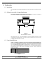
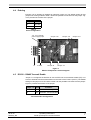
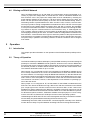
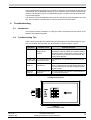
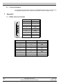
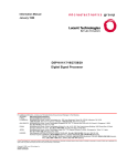
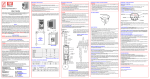
Operating Instructions
Serial Input/Output Converter
SIOC03
Table of Contents
Table of Contents
1
Introduction . . . . . . . . . . . . . . . . . . . . . . . . . . . . . . . . . . . . . . . . . . . . . . . . . . . . . . . . . . . . . . . . . . . . . . . . . . . 2
1.1 Product Overview . . . . . . . . . . . . . . . . . . . . . . . . . . . . . . . . . . . . . . . . . . . . . . . . . . . . . . . . . . . . . . . . . . . 2
1.2 Manual Overview . . . . . . . . . . . . . . . . . . . . . . . . . . . . . . . . . . . . . . . . . . . . . . . . . . . . . . . . . . . . . . . . . . . 2
2
Receiving and Installation . . . . . . . . . . . . . . . . . . . . . . . . . . . . . . . . . . . . . . . . . . . . . . . . . . . . . . . . . . . . . . . 2
2.1 Initial Inspection . . . . . . . . . . . . . . . . . . . . . . . . . . . . . . . . . . . . . . . . . . . . . . . . . . . . . . . . . . . . . . . . . . . . 2
2.2 Product Features & Specifications . . . . . . . . . . . . . . . . . . . . . . . . . . . . . . . . . . . . . . . . . . . . . . . . . . . . . . 2
3
Connections . . . . . . . . . . . . . . . . . . . . . . . . . . . . . . . . . . . . . . . . . . . . . . . . . . . . . . . . . . . . . . . . . . . . . . . . . . 3
3.1 Introduction . . . . . . . . . . . . . . . . . . . . . . . . . . . . . . . . . . . . . . . . . . . . . . . . . . . . . . . . . . . . . . . . . . . . . . . . 3
3.2 General Wiring Information . . . . . . . . . . . . . . . . . . . . . . . . . . . . . . . . . . . . . . . . . . . . . . . . . . . . . . . . . . . . 3
3.2.1 Wiring Practices . . . . . . . . . . . . . . . . . . . . . . . . . . . . . . . . . . . . . . . . . . . . . . . . . . . . . . . . . . . . . . . 3
3.2.2 Considerations for Control Wiring . . . . . . . . . . . . . . . . . . . . . . . . . . . . . . . . . . . . . . . . . . . . . . . . . . 3
3.2.3 RS232 Communication Cable. . . . . . . . . . . . . . . . . . . . . . . . . . . . . . . . . . . . . . . . . . . . . . . . . . . . . 3
3.3 Terminals Found on the SIOC03 . . . . . . . . . . . . . . . . . . . . . . . . . . . . . . . . . . . . . . . . . . . . . . . . . . . . . . . 3
3.3.1 Power Supply Connections . . . . . . . . . . . . . . . . . . . . . . . . . . . . . . . . . . . . . . . . . . . . . . . . . . . . . . . 4
3.3.2 RS233 Input Connections . . . . . . . . . . . . . . . . . . . . . . . . . . . . . . . . . . . . . . . . . . . . . . . . . . . . . . . . 5
3.3.3 RS485 Output Connections . . . . . . . . . . . . . . . . . . . . . . . . . . . . . . . . . . . . . . . . . . . . . . . . . . . . . . 5
4
Configuration . . . . . . . . . . . . . . . . . . . . . . . . . . . . . . . . . . . . . . . . . . . . . . . . . . . . . . . . . . . . . . . . . . . . . . . . . 6
4.1 Introduction . . . . . . . . . . . . . . . . . . . . . . . . . . . . . . . . . . . . . . . . . . . . . . . . . . . . . . . . . . . . . . . . . . . . . . . . 6
4.2 Gaining Access to the Configuration Jumpers . . . . . . . . . . . . . . . . . . . . . . . . . . . . . . . . . . . . . . . . . . . . . 6
4.3 Power Supply Selection . . . . . . . . . . . . . . . . . . . . . . . . . . . . . . . . . . . . . . . . . . . . . . . . . . . . . . . . . . . . . . 6
4.4 Echoing . . . . . . . . . . . . . . . . . . . . . . . . . . . . . . . . . . . . . . . . . . . . . . . . . . . . . . . . . . . . . . . . . . . . . . . . . . . 7
4.5 RS232 – RS485 Transmit Enable . . . . . . . . . . . . . . . . . . . . . . . . . . . . . . . . . . . . . . . . . . . . . . . . . . . . . . . 7
4.6 Biasing an RS-485 Network . . . . . . . . . . . . . . . . . . . . . . . . . . . . . . . . . . . . . . . . . . . . . . . . . . . . . . . . . . . 8
5
Operation . . . . . . . . . . . . . . . . . . . . . . . . . . . . . . . . . . . . . . . . . . . . . . . . . . . . . . . . . . . . . . . . . . . . . . . . . . . . . 8
5.1 Introduction . . . . . . . . . . . . . . . . . . . . . . . . . . . . . . . . . . . . . . . . . . . . . . . . . . . . . . . . . . . . . . . . . . . . . . . . 8
5.2 Theory of Operation . . . . . . . . . . . . . . . . . . . . . . . . . . . . . . . . . . . . . . . . . . . . . . . . . . . . . . . . . . . . . . . . . 8
6
Troubleshooting . . . . . . . . . . . . . . . . . . . . . . . . . . . . . . . . . . . . . . . . . . . . . . . . . . . . . . . . . . . . . . . . . . . . . . . 9
6.1 Introduction . . . . . . . . . . . . . . . . . . . . . . . . . . . . . . . . . . . . . . . . . . . . . . . . . . . . . . . . . . . . . . . . . . . . . . . . 9
6.2 Troubleshooting Tips. . . . . . . . . . . . . . . . . . . . . . . . . . . . . . . . . . . . . . . . . . . . . . . . . . . . . . . . . . . . . . . . . 9
6.3 Factory Assistance . . . . . . . . . . . . . . . . . . . . . . . . . . . . . . . . . . . . . . . . . . . . . . . . . . . . . . . . . . . . . . . . . 10
7
Appendix . . . . . . . . . . . . . . . . . . . . . . . . . . . . . . . . . . . . . . . . . . . . . . . . . . . . . . . . . . . . . . . . . . . . . . . . . . . . 10
7.1 RS232 Connection Details . . . . . . . . . . . . . . . . . . . . . . . . . . . . . . . . . . . . . . . . . . . . . . . . . . . . . . . . . . . 10
09.10.03
SIOC03_GB
Operating Instructions
Serial Input/Output Converter SIOC03
1
1
Introduction
1.1
Product Overview
The SIOC03 module is an optically isolated converter that converts RS232 to half duplexed
RS485 signals and vice-versa. The converter performs all necessary level shifting required
to interface these two different communication systems.
1.2
Manual Overview
This manual contains specifications, receiving and installation instructions, configuration,
description of operation, and troubleshooting procedures for the SIOC03 Serial Input/Output Converter.
2
Receiving and Installation
2.1
Initial Inspection
The SIOC03 option contains an SIOC03 converter module, two sets of cables for connecting to the EF1, and a 24 VDC power supply. One of the cables is for reflashing the drive's
firmware (marked WF2 Reflash and having an RJ45 connector); the other is for Modbus
communications (marked WF2 Modbus.)
Carefully inspect the SIOC03 for shipping damage or missing components. Report any
shipping damage to your nearest BERGES representative.
2.2
Product Features & Specifications
Power supply requirements +5 VDC or +12–24 VDC; 50 mA
Module input
RS232 for PC or PLC, 9 pin “D” shell, female
Module output
RS485 half duplex, to terminal block
Maximum baud rate
110 k bits per second (bps)
Signal Isolation
Optical, 1,000 volts
Rectified power supply input Power supply polarity makes no difference
Break apart terminal
Allows easy replacement, if needed
Ease of installation
Simple 2 wire half duplex requires a minimal number of electrical connections per device
Common protocols
Input RS232 is available on all PCs and many PLCs. Output
RS485 is common in industrial applications, providing flexibility in selection of other system components
Jumper selectable echoing Allows disabling of echo feature for compatibility with a greater number of devices and host software
LED diagnostics
PWR – power supply is OK.
TE – transmit enable is active.
TxD – data is present on the transmit line.
RxD – data is present on the receive line.
Jumper selectable RS232 - Allows selection between an Automatic Transmit Enable or
RS 485 Transmit Enable
an RTS/CTS Transmit Enable
Method
2
Operating Instructions
Serial Input/Output Converter SIOC03
09.10.03
SIOC03_GB
3
Connections
3.1
Introduction
This chapter provides information on connecting the required wiring to the SIOC03 converter.
3.2
General Wiring Information
3.2.1
Wiring Practices
Good wiring practice requires separation of low voltage wiring from all power wiring. Power
from inverters and other non-linear loads contain high frequencies that may interfere with
other equipment. Do not run low voltage signal wires in the same conduit or raceway with
power or motor wiring. Observe general RFI suppression measures (refer to the inverter
manuals (electromagnetic compatibility)).
3.2.2
Considerations for Control Wiring
All wiring associated with the SIOC03 converter module is low voltage wiring. Many of the
conductors carry high frequency signals that contain the communication signals. Select this
low voltage wiring as follows:
1. Shielded wire is recommended to prevent electrical noise interference from causing improper operation or nuisance tripping. Connect the shield as recommended by the
equipment manufacturer.
2. Twisted pairs are recommended. The SIO+ and SIO– conductors should be twisted together. If a twisted pair is used for the power supply connection, the positive voltage and
common conductors should be twisted.
3. Use only VDE, UL or CUL recognized wire.
4. Wire voltage rating must be at least 300 volts.
3.2.3
RS232 Communication Cable
It may be desirable to extend the length of the 9 pin “D” shell connector. To do this requires
a straight through cable assembly (i.e pin 1 connects to pin1; pin 2 to pin 2; etc.). Mouse
extension cables may not perform correctly. To assure reliability, always keep the length of
this connection as short as possible, with an absolute maximum of 25 feet. The cable
should be kept clear of any power signals.
3.3
Terminals Found on the SIOC03
Figure 1 shows the power SIOC03 circuit board assembly. The Table 1 describes the terminals.
09.10.03
SIOC03_GB
Operating Instructions
Serial Input/Output Converter SIOC03
3
Terminal Term
1
Description
PWR Positive input terminal for the power supply.
2&4
SIO+ Positive side of the SIO data.
3&5
SIO– Negative side of the SIO data.
6
J12
COM Circuit common for the power supply input.
2 mm female power supply input.
Table 1
Description of Terminals
J12; 2 mm female
power supply input
Jumper J16
Jumper J18
Jumper J19
1
2
3
4
5
6
J2
4 LEDs
Jumper J9
Jumper J17
Figure 1
SIOC03 Component Location Diagram
3.3.1
Power Supply Connections
The SIOC03 converter module requires a DC power supply to operate. The voltage can be
between +12 and +24 VDC.
When used with the “E-trAC WFC” or “WF2” series of drives, the +24 VDC can be taken
from the drive's user power supply. In this case, the +24 and common terminals of any one
drive in the system are connected to the V+ and COM terminals of the SIOC03. Do not, under any circumstances, connect the supply terminals of multiple devices to the SIOC03, or
damage may result to those devices. Other external supplies can also be used, and are
connected in the same manner.
The power supply requirement can also be met using a power supply adapter such as
BERGES part number PA24DC. Such a device must be capable of supplying +24 VDC, and
capable of supplying 50 mA of current. Power from these devices can be connected to the
J12 connector of the SIOC03 module. See figure 1 for the location of this connector.
4
Operating Instructions
Serial Input/Output Converter SIOC03
09.10.03
SIOC03_GB
3.3.2
RS233 Input Connections
The SIOC03 module is provided with a 9 pin “D” shell connector for interface with a PC,
PLC, or other RS232 communication host. Hardware is also provided for securing this connector to the host device. It is strongly suggested that the connector be secured using this
hardware.
If the length of the cable is adequate, and the gender of the connector are correct, the cable
can be plugged directly into the desired communications port (COM Port) of the host device.
It may be necessary to convert the gender of the 9 pin “D” shell connector. Adapters for this
type of conversion are available from third party sources. Details of the signals connected
to the various pins of this connector can be found in section 7.1.
If the communication host has a 25 pin “D” shell connector, an adapter can be made or purchased from a third party. Section 7.1 provides the connection information for such an
adapter.
The length of the input cable assembly can be extended. To do this requires a straight
through cable assembly (i.e pin 1 connects to pin 1; pin 2 to pin 2; etc.). Mouse extension
cables may not perform correctly. To assure reliability, always keep the length of this connection as short as possible, with an absolute maximum of 25 feet. The cable should be
kept clear of any power signals.
3.3.3
RS485 Output Connections
The RS485 output of the SIOC03 is terminated at COM, terminals SIO+ and SIO–. The
proper connection of these terminals, when connected to BERGES inverter products, is
shown in figure 2. Refer to the equipment manual for other devices that you may wish to
connect to the same system for correct connection.
It is strongly recommended that these connections be made with a shielded twisted pair.
The SIO+ and SIO– conductors are twisted. The shield is connected to the common of either the SIOC03 module or the device that it is communicating with; but not at both ends.
The end not connected should be taped back to the jacket of the cable. This is the case for
each connection, as shown in figure 2.
Figure 2
Typical RS485 Connections
09.10.03
SIOC03_GB
Operating Instructions
Serial Input/Output Converter SIOC03
5
4
Configuration
4.1
Introduction
This chapter provides information on setting the configuration jumpers in the SIOC03 module.
4.2
Gaining Access to the Configuration Jumpers
The case of the SIOC03 is removed by removing the two screws located on the bottom of
the enclosure. See figure 3 for the location of these screws.
Figure 3
Enclosure Screw Location
When replacing the cover, assure that the ribbon cable for the RS232 connection is routed
correctly and is not being pinched. The screws should not be tightened in excess of 6 in-lb,
or damage may result to the enclosure.
4.3
Power Supply Selection
Jumper J16 configures the SIOC03 module to supply current from the PWR connection on
jumper J2. This setting should only be used when connecting the SIOC03 to BERGES Enhanced Keypad. Note that having the jumper configured to EKP with another product
may cause damage to that product or the SIOC03. The default setting for this jumper is
DRV and should not be changed from this position unless an Enhanced Keypad (EKP) is
being reflashed. Refer to Table 2 for the proper jumper placement. Figure 4 provides the
location of the jumper.
Jumper J16 Label
Selection
1-2
DRV
No current source through J2-1
2-3
EKP
Current source through J2-1
Table 2
Power Supply Configuration
6
Operating Instructions
Serial Input/Output Converter SIOC03
09.10.03
SIOC03_GB
4.4
Echoing
Echoing can be enabled or disabled by selection jumper J9. The default setting for this
jumper has echoing enabled. Table 3 shows the possible connections for this jumper. Figure 4 provides the location of the jumper.
Jumper J9 Selection
1-2
Echo On
2-3
Echo Off
Table 3
Echo Configuration
J12; 2 mm female
power supply input
Jumper J16
Jumper J18
Jumper J19
1
2
3
4
5
6
J2
4 LEDs
Jumper J9
Jumper J17
Figure 4
SIOC03 Component Location Diagram
4.5
RS232 – RS485 Transmit Enable
Jumper J17 configures the SIOC03 to use the RTS line as the transmit enable (TE) or to
have an automatic transmit enable based on the state of the Txd line (AUTO.) The default
setting for this jumper is AUTO. Refer to table 4 for the possible connections for this jumper.
Figure 4 provides the location of the jumper.
Jumper J17 Label
Selection
1-2
TE
Transmit Enable by RTS
2-3
Auto
Automatic Transmit Enable
Table 4
Transmit Enable Configuration
09.10.03
SIOC03_GB
Operating Instructions
Serial Input/Output Converter SIOC03
7
4.6
Biasing an RS-485 Network
When an RS485 network is in an idle state (no communication is being transmitted or received), a proper idle voltage state of at least 200 mV must be maintained between the
SIO+ and SIO– lines. The proper idle voltage state must be maintained by selecting the
proper biasing resistors for the network. A 10k ohm pull-up resistor (R2) on the SIO+ line
and a 10k ohm pull down resistor (R20) on the SIO– line do the SIOC03 biasing. When a
terminating resistor is placed between the SIO+ and SIO– lines, however, 10k ohm resistors may not produce enough voltage difference between the SIO+ and SIO– lines to signal
an idle state. As the voltage difference between SIO+ and SIO– increases, the probability
of corrupt communication increases. The SIOC03 provides a method of reducing the biasing resistors to improve communications for the terminated, noisy, or multi-dropped network. Jumpers J18 and J19 place a 1k ohm resistor in parallel with the 10k ohm bias resistors dropping the biasing to 910 ohms. This will increase the voltage difference between the
SIO+ and SIO– communication lines. Figure 4 shows the position of the jumpers when the
extra resistance is not added. The SIOC03 also provides a place to add through hole resistors (R49, R50) in parallel to the biasing resistors so that the resistance can be dropped
even further.
5
Operation
5.1
Introduction
This chapter provides information on the operation of the SIOC03 Serial Input/Output Converter.
5.2
Theory of Operation
The SIOC03 module provides a half-duplex (2-wire) RS485 multi-drop connection designed
primarily for use with the BERGES inverter products. All drives on the common RS485 bus
must have their circuit commons (COM or CM terminal) connected. The optical isolation of
the SIOC03 provides an isolation barrier between the drives and the communication host.
This isolation allows baud rates of up to 110 kHz.
When jumper J17 is configured to AUTO, the transmitter for the RS485 is enabled as long
as no activity is detected on the Txd line of the RS232 device. When the SIOC03 detects
the start character of a message it stops all RS485 transmissions so that the RS232 side
can transmit. Because the SIOC03 must detect the activity of the RS232 device, the automatic mode is more susceptible to communication errors than the RTS transmit enable.
This method of conversion, however, is less dependent on host software or operating system of the host device.
When jumper J17 is configured to TE, the transmitter for the RS485 is enabled when the
RTS line is low. When the RTS line is high, data on the TxD line is reflected on the RS485
port. A high signal on the TxD line causes current to flow from SIO+ to SIO-. Data on the
RS485 bus is always reflected on the RxD line, regardless of the RTS signal level. All TB
Wood's PC software will work with RTS transmit enable on PCs with Windows 9x systems.
For NT based systems, however, TB Wood's software will require jumper J17 to be configured to AUTO due to restrictions to COM port access in those operating systems.
Handshaking lines RTS and CTS are connected together internally in the SIOC03 module.
No time delay is injected between asserting RTS and receiving CTS.
Handshaking lines DTR, DSR, and DSD are connected together internally in the SIOC03
module. No time delay is injected between asserting DTR and receiving DSR and DCD.
8
Operating Instructions
Serial Input/Output Converter SIOC03
09.10.03
SIOC03_GB
These handshaking connections are present for software or hardware that requires full
handshaking. Use of BERGES software on most computers does not require the full handshaking, and operation may be accomplished by proper connection of only the GND, RTS,
TxD and RxD signals.
Transmission of data is enabled by raising the RTS signal prior to sending data on the TxD
line. The transmitter is enabled with 20 microseconds of the RTS assertion.
6
Troubleshooting
6.1
Introduction
This chapter provides information on using the LEDs incorporated into the design of the
SIOC03 as troubleshooting aids.
6.2
Troubleshooting Tips
Table 5 presents a guide for troubleshooting a system based on the status LEDs in the system. The location of these LEDs, and their function, is shown in figure 1 and 5.
Symptom
Possible Cause
Potential Solution
PWR LED not Correct power supply Check that the power supply is connected, and that
lit
voltage is not
it is working correctly. Check for excessive load on
present.
the power supply. Check that the power supply selection jumper in the SIOC2 is set correct for the
voltage being applied.
TE LED not lit TE command not giv- Check that the TE command is being sent by the
during transmit en in source code.
host.
TxD never
comes on
No signal on the
transmit line.
Check the RS232 connections (9 pin “D” shell connector). Assure that the host is putting information
onto the transmit bus, and that the signal is reaching the module.
RxD never
comes on
No signal on the receive line.
Check the RS485 connections to J2 and the devices connected to the bus.
Table 5
Troubleshooting Hints
Figure 5
Location of Status LEDs
09.10.03
SIOC03_GB
Operating Instructions
Serial Input/Output Converter SIOC03
9
6.3
Factory Assistance
If you require further assistance with this or any BERGES Electrical product, please contact
our Application Engineers can be reached at +49 2264 17-158 or +49 2264 17-160.
7
Appendix
7.1
RS232 Connection Details
Pin Number
Signal Name
1
DCD
2
RxD
3
TxD
4
DTR
5
GND
6
DSR
7
RTS
8
CTS
9
9 Pin “D” Shell Connections, SIOC03 and Host
25 Pin D Shell Host 9 Pin RS232, SIOC03
Signal Name
2
3
TxD
3
2
RxD
4
7
RTS
5
8
CTS
6
6
DSR
7
5
GND
8
1
DCD
20
4
DTR
9 Pin to 25 Pin Serial Port Connections
10
Operating Instructions
Serial Input/Output Converter SIOC03
09.10.03
SIOC03_GB
BERGES electronic GmbH
Industriestraße 13 • D–51709 Marienheide-Rodt
Postfach 1140 • D–51703 Marienheide
Tel. (0 22 64) 17-0 • Fax (0 22 64) 1 71 26
http://www.berges.de • e-mail: [email protected]