1
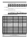
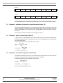
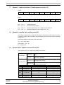
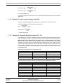
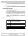
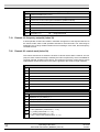
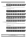
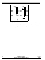
®
BERGES
Operating Instructions
ACM-D2
Serial Data Transmission
BERGES Protocol
Translation based on document D2STDDI.DOC, revision 31.07.98.
© 2003 BERGES electronic s.r.l. All rights reserved.
Table of Contents
1
Introduction . . . . . . . . . . . . . . . . . . . . . . . . . . . . . . . . . . . . . . . . . . . . . . . . . . . . . . . . . . . . . . . . . . . . . . . . . . . 2
1.1
BERGES protocol . . . . . . . . . . . . . . . . . . . . . . . . . . . . . . . . . . . . . . . . . . . . . . . . . . . . . . . . . . . . . . . . 2
1.2
Extended BERGES protocol . . . . . . . . . . . . . . . . . . . . . . . . . . . . . . . . . . . . . . . . . . . . . . . . . . . . . . . . 2
1.3
ISO protocol . . . . . . . . . . . . . . . . . . . . . . . . . . . . . . . . . . . . . . . . . . . . . . . . . . . . . . . . . . . . . . . . . . . . . 2
2
General information about the BERGES protocol . . . . . . . . . . . . . . . . . . . . . . . . . . . . . . . . . . . . . . . . . . . . 2
3
Frame structure of the BERGES protocol (frame start byte = 99H) . . . . . . . . . . . . . . . . . . . . . . . . . . . . . . 3
4
Frame structure of the extended BERGES protocol (frame start byte = AAH) . . . . . . . . . . . . . . . . . . . . . 4
5
Protocol parameter manipulation . . . . . . . . . . . . . . . . . . . . . . . . . . . . . . . . . . . . . . . . . . . . . . . . . . . . . . . . . 4
5.1
CONTR byte. . . . . . . . . . . . . . . . . . . . . . . . . . . . . . . . . . . . . . . . . . . . . . . . . . . . . . . . . . . . . . . . . . . . . 4
5.2
INDEX byte . . . . . . . . . . . . . . . . . . . . . . . . . . . . . . . . . . . . . . . . . . . . . . . . . . . . . . . . . . . . . . . . . . . . . 5
5.3
Data format (data byte DAT-H, DAT-L) . . . . . . . . . . . . . . . . . . . . . . . . . . . . . . . . . . . . . . . . . . . . . . . . 5
6
Index list ACM-D2 (D2A-STD-014 software) . . . . . . . . . . . . . . . . . . . . . . . . . . . . . . . . . . . . . . . . . . . . . . . . . 5
7
Description of individual indexes . . . . . . . . . . . . . . . . . . . . . . . . . . . . . . . . . . . . . . . . . . . . . . . . . . . . . . . . . 7
8
7.1
Remark 1: range of ramp times (index 02...05) . . . . . . . . . . . . . . . . . . . . . . . . . . . . . . . . . . . . . . . . . . 7
7.2
Remark 2: reduction V/f braking phase (index 09). . . . . . . . . . . . . . . . . . . . . . . . . . . . . . . . . . . . . . . . 7
7.3
Remark 3: configuration of relay and open-collector outputs (index 0F...11). . . . . . . . . . . . . . . . . . . . 7
7.4
Remark 4: activation of external current threshold (index 12) . . . . . . . . . . . . . . . . . . . . . . . . . . . . . . . 8
7.5
Remark 5: motor current limit (index 19) . . . . . . . . . . . . . . . . . . . . . . . . . . . . . . . . . . . . . . . . . . . . . . . 8
7.6
Remark 6: current limit hysteresis (index 1A) . . . . . . . . . . . . . . . . . . . . . . . . . . . . . . . . . . . . . . . . . . . 8
7.7
Remark 7: rotation direction of fixed frequencies (index 1F) . . . . . . . . . . . . . . . . . . . . . . . . . . . . . . . . 9
7.8
Remark 8: setpoint input scaling (index 22) . . . . . . . . . . . . . . . . . . . . . . . . . . . . . . . . . . . . . . . . . . . . . 9
7.9
Remark 9a/9b: LEVELS (indexes 29 and 2A) . . . . . . . . . . . . . . . . . . . . . . . . . . . . . . . . . . . . . . . . . . . 9
7.10
Remark 10: extended parameterisation (index 2B) . . . . . . . . . . . . . . . . . . . . . . . . . . . . . . . . . . . . . . 10
7.11
Remark 11: output frequency display (index 2C) . . . . . . . . . . . . . . . . . . . . . . . . . . . . . . . . . . . . . . . . 10
7.12
Remark 12: motor voltage display (index 2D) . . . . . . . . . . . . . . . . . . . . . . . . . . . . . . . . . . . . . . . . . . 10
7.13
Remark 13: motor current display (index 2E). . . . . . . . . . . . . . . . . . . . . . . . . . . . . . . . . . . . . . . . . . . 11
7.14
Remark 14: keyboard & display (indexes 2F...32) . . . . . . . . . . . . . . . . . . . . . . . . . . . . . . . . . . . . . . . 11
7.15
Remark 15: software version (index 34) . . . . . . . . . . . . . . . . . . . . . . . . . . . . . . . . . . . . . . . . . . . . . . 12
7.16
Remark 16: SIO timeout (index 35) . . . . . . . . . . . . . . . . . . . . . . . . . . . . . . . . . . . . . . . . . . . . . . . . . . 12
7.17
Remark 17: error code (index 37) . . . . . . . . . . . . . . . . . . . . . . . . . . . . . . . . . . . . . . . . . . . . . . . . . . . 12
7.18
Remark 18: status word (index 38) . . . . . . . . . . . . . . . . . . . . . . . . . . . . . . . . . . . . . . . . . . . . . . . . . . 13
7.19
Remark 19: frequency setpoint (index 39) . . . . . . . . . . . . . . . . . . . . . . . . . . . . . . . . . . . . . . . . . . . . . 14
7.20
Remark 20: control word (index 3A). . . . . . . . . . . . . . . . . . . . . . . . . . . . . . . . . . . . . . . . . . . . . . . . . . 14
Examples . . . . . . . . . . . . . . . . . . . . . . . . . . . . . . . . . . . . . . . . . . . . . . . . . . . . . . . . . . . . . . . . . . . . . . . . . . . . 15
8.1
Setting the maximum frequency to 50.0 Hz (with slave reply) . . . . . . . . . . . . . . . . . . . . . . . . . . . . . . 15
8.2
Setting the frequency setpoint to 30.0 Hz (without slave reply) . . . . . . . . . . . . . . . . . . . . . . . . . . . . . 15
8.3
Output frequency display . . . . . . . . . . . . . . . . . . . . . . . . . . . . . . . . . . . . . . . . . . . . . . . . . . . . . . . . . . 16
8.4
Setting the setpoint reference to the Loc mode . . . . . . . . . . . . . . . . . . . . . . . . . . . . . . . . . . . . . . . . . 16
8.5
Example of a range violation (Fmax set to 655 Hz) . . . . . . . . . . . . . . . . . . . . . . . . . . . . . . . . . . . . . . 17
8.6
Example of CRC calculation . . . . . . . . . . . . . . . . . . . . . . . . . . . . . . . . . . . . . . . . . . . . . . . . . . . . . . . 17
12.03.03
Operating Instructions
STDG1
Serial data transmission (BERGES protocol)
1
1
Introduction
The D2A-STD software range supports independent serial data protocols over the serial interface. The inverter recognises the protocol automatically and so the user does not need
to configure the protocol used.
1.1
BERGES protocol
This protocol uses a block process with FEC (forward error correction) for error handling,
thus enabling “secure” data transmission. Thanks to the compact structure of the data
frame used and the simple protocol structure, the highest data transfer rate can be
achieved with this protocol. Refer to the corresponding documents for further information
about the BERGES protocol. The following text describes this protocol.
1.2
Extended BERGES protocol
This has the same structure as the BERGES protocol, with the exception that inverter addresses up to the value 127 are accepted.
1.3
ISO protocol
Refer to the corresponding documents for further information about the ISO protocol.
2
General information about the BERGES protocol
A master/slave process is used. The master device is defined by its address (addr. = 0). All
other devices are slave and so no arbitration mechanism is provided. Only the master device is allowed to start a transfer or polling. Slaves can communicate with one another via
the master only (i.e.: during every transfer, the master must appear either as the sender or
the recipient).
It is possible to write all inverters (slaves) simultaneously from the master (address = 0) with
the broadcast function (Write-Only). Thus, when changing Fmax to 60 Hz, for example, it is
not necessary to singly address all inverters (slaves) with the corresponding address (SIO
address set on the inverter) and the broadcast function can be used instead (Write-Only).
The SIO addresses (SIO address > 0) of the inverters (slaves) cannot be adjusted with the
broadcast function, except in the case of an inverter that has not yet been addressed (SIO
address = 0) on the RS485 bus, which can be set to a still free address with the broadcast
function. If an inverter is set to an address > 15 (extended BERGES protocol (frame start
byte = AAH)), the address can also be adjusted with the BERGES protocol (frame start byte
= 99H) via the broadcast function.
The data is secured with a BLOCK CODE (line and column parities). In the receiving device,
an FEC (forward error correction) process is used for error correction, and so simple errors
can be corrected. Error bursts are also corrected provided they concern only one data byte.
The data block affected is rejected if multiple errors are detected (this is not reported back!).
TRANSFER:
2
1 start bit, 8 data bits, 1 stop bit, 9600 Baud
e.g. Mode COM2: 9600, n, 8, 1.
Operating Instructions
12.03.03
Serial data transmission (BERGES protocol)
STDG1
Data transfer times
3
Frame structure of the BERGES protocol
(frame start byte = 99H)
STF
BYTE0
Byte
ADDR
CONTR
BYTE1
BYTE2
INDEX
DAT-H
BYTE3
BYTE4
Designation
DAT-L
BYTE5
CRC-R
BYTE6
CRC-L
BYTE7
Description
BYTE0 STF
Frame start byte: by virtue of this byte, the recipient recognises
the required protocol and indicates the start of a data frame
BYTE1 ADDR
Address byte:
SA: BIT7...BIT4:
EA: BIT3...BIT0:
Slave addresses:
Slave address 0:
BYTE2 CONTR
Control byte
BYTE3 INDEX
Index byte
BYTE4 DAT-H
Data byte, high byte
BYTE5 DAT-L
Data byte, low byte
BYTE6 CRC-R
Column parity (even): the frame start byte (BYTE0) is not secured
as well
BYTE7 CRC-L
Line parity (even): CRC-R is also taken into account
Sender´s address
Recipient´s address
1...15
no serial transfer
12.03.03
Operating Instructions
STDG1
Serial data transmission (BERGES protocol)
3
4
Frame structure of the extended BERGES protocol
(frame start byte = AAH)
STF
BYTE0
Byte
5
ADDR
CONTR
BYTE1
BYTE2
INDEX
BYTE3
DAT-H
BYTE4
Designation
DAT-L
BYTE5
CRC-R
BYTE6
CRC-L
BYTE7
Description
BYTE0 STF
Frame start byte: by virtue of this byte, the recipient recognises
the required protocol and indicates the start of a data frame
BYTE1 ADDR
Address byte:
SA: BIT7 = 1
EA: BIT7 = 0
BIT6...BIT0 =
Slave addresses:
Slave address 0:
BYTE2 CONTR
Control byte
BYTE3 INDEX
Index byte
BYTE4 DAT-H
Data byte, high byte
BYTE5 DAT-L
Data byte, low byte
BYTE6 CRC-R
Column parity (even): the frame start byte (BYTE0) is not secured
as well
BYTE7 CRC-L
Line parity (even): CRC-R is also taken into account
(to the master): Sender´s address
(to the slave): Recipient´s address
Slave address
1...127
no serial transfer
Protocol parameter manipulation
5.1
CONTR byte
The Contr byte serves to “switch over” the PROTOCOL for special applications, for polling
and for protocol control (Write/Read). It is handled as follows:
Contr byte = 00H Polling
The slave addressed responds with the STATUS WORD (index 38) or with the ERROR
CODE (index 37) if an error has occurred. Consequently, the polling block is also suitable
for querying the inverter´s status.
Contr byte, BIT7
Reply flag (read flag)
The master requests a reply from the slave when a BIT7 is set. The slave replies only if explicitly requested to do so (BIT7 set). If a CONVERTER ERROR has occurred, it replies in
any case with the ERROR CODE (index 37). The keyboard (index 2F to 32), which responds with the display content in any case, is an exception to this. If a slave responds with
the BIT7 set, a protocol error is thus signalled to the master (e.g. a special application is not
supported, range violations, attempt to write to read-only index, etc.).
Contr byte, BIT0
change parameter (write flag)
When set, BIT0 causes the slave to accept a parameter. A range check takes place in the
slave. In the event of a range violation, an error flag is set (BIT7 in the next reply) and, depending on the index, the corresponding limit is accepted or the value is rejected.
4
Operating Instructions
12.03.03
Serial data transmission (BERGES protocol)
STDG1
Contr byte, BIT1...BIT6 = 0 ACM-D2
1
x
x
x
READ
x
x
BIT6
BIT5
BIT4
BIT3
1
WRITE
ACM-D2 BIT6...BIT1 = 0
BIT7
5.2
x
BIT2
BIT1
BIT0
INDEX byte
The index byte serves to specify the required parameter and the associated reply parameter (if a reply is requested).
5.3
Data format (data byte DAT-H, DAT-L)
Data format: 16-bit integer unsigned (unless otherwise specified).
DAT-H (high byte)
DAT-L (low byte)
BIT7 BIT6 BIT5 BIT4 BIT3 BIT2 BIT1 BIT0 BIT7 BIT6 BIT5 BIT4 BIT3 BIT2 BIT1 BIT0
6
Index list ACM-D2 (D2A-STD-014 software)
Index
00
[1]
Parameter
Description
Inverter value
Index value
Default
3
Maximum frequency
6...650 Hz
600...65000
5000
01
4
Minimum frequency
0...Fmax
0...Index 00
0
02
5
Startup time, ramp 1
0.05...1000 sec.
Remark 1 (page 7)
03
6
Slow-down time, ramp 1
0.05...1000 sec.
Remark 1 (page 7)
04
E
Startup time, ramp 2
0.05...1000 sec.
Remark 1 (page 7)
0.05...1000 sec.
Remark 1 (page 7)
05
F
Slow-down time, ramp 2
06
[1]
7
V/f ratio
30...650 Hz
3000...65000
5000
07
[1]
8
BOOST
0...40%
0...400
50
08
[1]
8+
Dynamic BOOST
0...50%
0...50
0
09 [1]
8-
V/f reduction Braking phase
0...20%
100...80
Remark 2 (page 7)
80
0A [1]
9
Static torque
0...25 sec.
0...250
251 → continuous static
torque
20
0B [1]
t
DC brake activation time
0...20 sec.
0...200
0
DC brake intensity
0...50%
0...50
15
0C
[1]
DC
0D
[1]
U
Frequency threshold FX1
0...Fmax
0...Fmax
5000
0E
[1]
u
Frequency threshold FX2
0...Fmax
0...Fmax
1000
0F
REL
Config. relay output
-11...0...+11
Remark 3 (page 7)
10
OC1
Config. open-collector
-11...0...+11
Remark 3 (page 7)
11
OC2
Config. open-collector
-11...0...+11
Remark 3 (page 7)
12
S
0 = Loc/1 = Rem
Remark 4 (page 8)
13
BrLim
0...15
0...15
0
0, 1, 2, 4, 6, 8 (0...5)
0...5
0
5...650 Hz
500...65000
5000
14
15
[1]
Activ. current threshold, external
Software braking protection
DIS
Display configuration
Fm
Final analog output value
12.03.03
Operating Instructions
STDG1
Serial data transmission (BERGES protocol)
5
Index
Parameter
Description
Inverter value
Index value
Default
Setpoint input selection
1...5
0...4
0
16
REF
17
FILTER
Digital filter
0...6
0...6
3
18
S - INT
Handling of motor current limit
0...4
0...4
0
Limit: motor current
0...200%
0...255
Remark 5 (page 8)
150
Hysteresis: current limit
2...30%
3...39
Remark 6 (page 8)
4
Deceleration time: limit handling
0...20 sec.
0...200
50
19 [1]
S
1A [1]
HYS
1B [1]
DY
1C
[1]
FFIX
Fixed frequency 1
0...650 Hz
0...65000
500
1D
[1]
FFIX
Fixed frequency 2
0...650 Hz
0...65000
1000
1E
[1]
FFIX
Fixed frequency 3
0...650 Hz
0...65000
2000
1F
FFIX
Fixed-frequency rotation direction
Remark 7 (page 9)
00000000
20
A. out
Config. analog output
0...2
0...2
0
21
CLIP
Clipping
0...15
0...15
2
40...100%
0...60
Remark 8 (page 9)
0
OFF, ON, Mpt1,
Mpt2 (0...3)
0...3
0
0...100%
0...100
0
0 = linear/1 = quadrat.
0...1
0
22 [1]
Fk
Setpoint input scaling
23
JOG
24
AO
Fine tuning: output frequency
25
JOG mode and motor potentiometer
FFB
Profile of V/f characteristic
[1]
FFB
BOOST form factor
0...255
0...255
196
27 [1]
MOD
Modulation depth
0...255
0...255
ACM230V 230
ACM400V 245
28
R_Sel
Activation of second ramp set
0...4
0...4
0
26
29
[1]
Off LEVELS
Remark 9a (page 9)
11111111
2A
[1]
Active LEVELS
Remark 9b (page 9)
00000000
ON, OFF
Remark 10 (page 10)
10111010
0...Fmax
Remark 11 (page 10)
2B
2C
SUB XPAR Extended parameterisation
[1]
2D
2E
2F
Output frequency display
2
Motor voltage display
0...100...x%
Remark 12 (page 10)
Read value
I
Motor current display
0...200%
Remark 13 (page 11)
Read value
[1]...32
33
Keyboard & display Local/Remote
SIO
34
35
1
Software
[1]
Remark 14 (page 11)
0...15
(BERGES protocol)
A valid value is stored in non-volatile memory; the
0...127
values is ignored in the event of a range violation.
(extended BERGES protocol)
SIO address
Software version
Remark 15 (page 12)
SIO Timeout
Remark 16 (page 12)
Read value
36
Reserved
37
Error code
Remark 17 (page 12)
Read value
Status word
Remark 18 (page 13)
Read value
38
39
[1]
Frequency setpoint
3A
Control word
3B
F Local
3C
Reserved
3D
Reserved
6
0...Fmax
Remark 19 (page 14)
Remark 20 (page 14)
Value for internal works diagnosis
Read value
Operating Instructions
12.03.03
Serial data transmission (BERGES protocol)
STDG1
Index
Parameter
3E
Description
Inverter value
Index value
Default
Reserved
3F
Reserved
40
[1]
a
Locking freq. 1, low limit
0...650 Hz
0...Index 41
0
41
[1]
A
Locking freq. 1, high limit
0...650 Hz
Index 40...Index 42
0
42
[1]
b
Locking freq. 2, low limit
0...650 Hz
Index 41...Index 43
0
43
[1]
B
Locking freq. 2, high limit
0...650 Hz
Index 42...Index 44
0
44
[1]
c
Locking freq. 3, low limit
0...650 Hz
Index 43...Index 45
0
45
[1]
C
Locking freq. 3, high limit
0...650 Hz
Index 44...Index 46
0
46
[1]
d
Locking freq. 4, low limit
0...650 Hz
Index 45...Index 47
0
47
[1]
D
Locking freq. 4, high limit
0...650 Hz
Index 46...65000
0
48
[1]
s
Compensation frequency
0...20 Hz
0...2000
0
49
[1]
zero
4A
[1]
x
Idle current
0...110
Frequency threshold compensation
0...110
0.5...30 Hz
[2]
0
50...3000
50
[1] The index is set to its limit if the value range is violated.
[2] With A5 A5, the momentary current is defined as the idle current.
7
Description of individual indexes
7.1
Remark 1: range of ramp times (index 02...05)
All ramp times are defined via two indexes. The range and the time resolution are defined
via the ramp code (DAT-H: BIT0 and BIT1). DAT-L contains the actual ramp value. The value is ignored in the event of range violations.
7.2
Ramp time in sec.
DAT-H Ramp code
DAT-L Index value
0.05...2.00
0
5...200
02.0...20.0
1
20...200
020...200
2
20...200
40 × 5...200 × 5 (200–1000)
3
40...200
Remark 2: reduction V/f braking phase (index 09)
A value of 80 corresponds to a reduction of 20%.
Conversion between index value and inverter value:
[8–] = 100–index value
Index value = 100–[8–]
[8–] = reduction V/f braking phase in %.
7.3
Remark 3: configuration of relay and open-collector outputs (index 0F...11)
The indexes 0F to 11 serve to configure the signalling outputs (relay, OC1, OC2). The index
is supported as follows:
12.03.03
Operating Instructions
STDG1
Serial data transmission (BERGES protocol)
7
DAT-H:
0
BIT7
0
BIT6
0
BIT5
0
BIT4
0
BIT3
0
BIT2
0
BIT1
0
BIT0
DAT-L:
0
BIT7
0
BIT6
0
BIT5
OC/Rel
BIT4
OC/Rel
BIT3
OC/Rel
BIT2
OC/Rel
BIT1
OC/Rel+–
BIT0
OC/Rel contains the selection coding (value range: 0...11). The bit field OC/Rel+– contains
the associated sign (0 → negative). The value is ignored in the event of range violations.
7.4
Remark 4: activation of external current threshold (index 12)
The current threshold (index 19) can only be read out if this index is set to Rem. The current
value is adopted if it is reset to Local. If data is written to this index in the Rem mode, the
value is not adopted, but no protocol error is reported (BIT7 of the Contr byte is not set by
the slave).
The current Rem value is adopted if it is changed over to Loc.
7.5
Remark 5: motor current limit (index 19)
A limit is set as a percentage of the inverter's rated current. The inverter's response to
reaching of this limit can be set. Reaching of the limit can be signalled via the inverter's REL,
OC1 and OC2 outputs.
Conversion between index value and inverter value:
Index value
S[%] = ------------------------------ × 200
255
S[%] × 255
Index value = ----------------------------200
S = motor current limit in %.
7.6
Remark 6: current limit hysteresis (index 1A)
The effective hysteresis of the motor current limit when ramp reduction is active is set with
this index. This counteracts a tendency of the drive to oscillate.
Conversion between index value and inverter value:
Index value + 1
HYS[%] = ---------------------------------------2
Index value = ( 2 × HYS[%] ) – 1
HYS = current limit hysteresis in %.
8
Operating Instructions
12.03.03
Serial data transmission (BERGES protocol)
STDG1
7.7
Remark 7: rotation direction of fixed frequencies (index 1F)
DAT-H:
0
BIT7
0
BIT6
0
BIT5
0
0
BIT4
BIT3
0
0
BIT2
0
BIT1
BIT0
DAT-L:
0
BIT7
7.8
0
BIT6
Fix3_V
BIT5
Fix3_KL
Fix2_V
BIT4
BIT3
Fix2_KL
BIT2
Fix1_V
BIT1
Fix1...3_V = 1
Clockwise rotation
Fix1...3_V = 0
Counterclockwise rotation
Fix1...3_KL = 1
Rotation depending on the control input (terminal 15)
Fix1...3_KL = 0
Rotation depending on the setting of Fix1...3_V
Fix1_KL
BIT0
Remark 8: setpoint input scaling (index 22)
The reference signal can be scaled via this index. The programmed final values of the output frequency range are reached at the percentage of the final scale values entered by
means of Fk.
Conversion between index value and inverter value:
Fk = 100 – Index value
Index value = 100 – Fk
Fk = scaling in %.
7.9
Remark 9a/9b: LEVELS (indexes 29 and 2A)
These indexes serve to configure the digital control inputs.
0 (Remote);
the corresponding function is controlled via the serial interface
1 (Local);
the corresponding function is controlled via the digital
control input (terminal)
Index 29 = 1;
setting the logic level of the corresponding digital control
input (high or low-active)
Index 29 = 0;
Activates (1) or deactivates (0) the corresponding function via the serial interface
29 (OffLEVEL)
2A (ActivLEVEL)
Description
Index 2A (ActivLEVEL)
Index 29 (OffLEVEL)
BIT7
Terminal 30
0
1
BIT6
Terminal 26
0
1
BIT5
Terminal 25
0
1
BIT4
Terminal 24
0
1
BIT3
Terminal 23
0
1
12.03.03
Operating Instructions
STDG1
Serial data transmission (BERGES protocol)
9
Description
Index 2A (ActivLEVEL)
Index 29 (OffLEVEL)
BIT2
Terminal 16
0
1
BIT1
Terminal 15
0
1
BIT0
Terminal 11
0
1
NOTE:
The “active” logic/OffLEVELS are modified, not the ones that can be modified on the keyboard. Therefore, the keyboard values become active again when the inverter is restarted.
This avoids inadmissible terminal configurations (e.g. inactive lock) when starting the inverter.
7.10
Remark 10: extended parameterisation (index 2B)
The index 2B (SW1...SW8) is handled as follows:
DAT-L
Description
Range
Default
BIT7
DC brake
ON (1), OFF (0)
1 (ON)
BIT6
Config. of inputs START/STOP
and REVERSING
ON (1), OFF (0)
0 (OFF)
BIT5
Config. of error reset
ON (1), OFF (0)
1 (ON)
BIT4
Fmin operation
ON (1), OFF (0)
1 (ON)
BIT3
Config. of error signalling relay
ON (1), OFF (0)
1 (ON)
BIT2
DC brake frequency trigger
ON (1), OFF (0)
0 (OFF)
BIT1
Config. of Autostart function
ON (1), OFF (0)
1 (ON)
BIT0
Activation of “S” ramp
ON (1), OFF (0)
0 (OFF)
NOTE:
The value is ignored in the event of range violations.
7.11
Remark 11: output frequency display (index 2C)
The index 2C serves to query the inverter's output frequency. When data is written to this
index, the setpoint frequency is modified (changeover of the setpoint reference to remote
operation). The setpoint reference can be reset to the local mode via the CONTROL WORD
(index = 3A).
7.12
Remark 12: motor voltage display (index 2D)
MOD 0...255
ACM 230V: 230
/
ACM 400V: 245
When the depth of modulation parameter MOD (index 27) is left set to the default, this results is a range of 0...100% for the voltage display. The actual value then covers a range
(for 0...100% of the maximum voltage) of 0...230 (230 V unit) or 0...245 (400 V unit).
If the depth of modulation is modified, the result is an index value of 0 to depth of modulation. However, the percentage shown in the inverter display (and thus the voltage in %) always refers to the value specified for the respective inverter (230 V unit: 230/400 V unit:
245). Apart from a certain amount of saturation in the dc link circuit, you can calculated with
the following linear formulas:
Conversion between index value and inverter value:
10
Operating Instructions
12.03.03
Serial data transmission (BERGES protocol)
STDG1
Index value
230 V unit: U[%] = ------------------------------ × 100
230
Index value
400 V unit: U[%] = ------------------------------ × 100
245
U = motor voltage in %.
A depth of modulation that has been set to a value above the default results in percentages
above 100.
7.13
Remark 13: motor current display (index 2E)
The motor current is display in the range from 0...200% of the unit's rated current.
Conversion between index value and inverter value:
Index value
I[%] = ------------------------------ × 200
255
I[%] × 255
Index value = -------------------------200
I = motor current in %.
7.14
Remark 14: keyboard & display (indexes 2F...32)
The indexes 2F to 32 serve to remotely control the keyboard via the serial interface and to
query the display's content. This permits remote control via the inverter's menu structure.
Write access to this index results in switching over of the keyboard to the remote
mode. Read access switches the keyboard back to the local mode. In the event of range
violations, the value is ignored and the keyboard is switched to the local mode. for safety
reasons, only the SIO address of the inverter cannot be modified via the indexes 2F to 32.
The terminal configuration can also be sent. In this case, BIT0 of the DAT-L byte is set to
one. Contrary to what is otherwise generally usual, the response to an inverter error is not
an ERROR CODE.
Reply frames depending on the requested index:
INDEX
DAT-H
DAT-L
2F
Digit 1
Digit 2
30
Digit 3
Digit 4
31
Digit 5
Digit 6
32
Digit 7
Digit 8
Remote keyboard operation and terminal configuration are supported as follows:
DAT-H
DAT-L
BIT7
Terminal 30
SHIFT key
BIT6
Terminal 26
DEC key
BIT5
Terminal 25
INC key
BIT4
Terminal 24
SELECT key
BIT3
Terminal 23
BIT2
Terminal 16
BIT1
Terminal 15
BIT0
Terminal 11
12.03.03
Operating Instructions
STDG1
Serial data transmission (BERGES protocol)
(DAT-H: terminals “No/Yes”)
11
If BIT0 of the DAT-L byte is a one, the protocol interprets DAT-H as transfer of the “master
terminal states”. However, remotely controlled terminal must first be “disconnected” from
the inverter's terminal panel with the aid of index 29.
7.15
Remark 15: software version (index 34)
This is a read-only index that provides information about the inverter software in use. DATH contains the code for the software type, while DAT-L contains the current software version.
7.16
Remark 16: SIO timeout (index 35)
The timeout serves to intercept uncontrolled inverter states as might be possible in the
event of an interruption in the RS485 connection:
If BIT7 in the DAT-L byte is zero, after the timeout has elapsed the inverter is shut down to
0 via the slow down ramp and the states for the display, keyboard, setpoint and terminals
are reset to the local mode. “Time Out” appears on the display until the inverter is once
again addressed via the serial interface or the device is switched off and then switched on
again.
The timeout range is from 0...127, a value of 1...127 corresponding to a timeout of 0.1...12.7
sec. Timeout monitoring is stopped if the value 0 is passed on.
The SIO timeout index also supports shutdown of an RS485 connection. BIT7 in the DATL byte must be set. Bits 0...6 in the DAT-L byte (0...127) reflect the timeout time. After the
timeout has elapsed, only the states for the display, keyboard, setpoint and terminals are
reset to the local mode.
7.17
Remark 17: error code (index 37)
DAT-H contains the error flag, and so it reports occurring errors or faults. It must be reset
via the terminals or the terminals controlled with the index 2A.
DAT-H Error flag
BIT7
Deactivation due to excess current (OVERLOAD)
BIT6
Deactivation due to excess inverter temperature (OVERTEMP)
BIT5
Deactivation due to excess voltage (OVERVOLT)
BIT4
BIT3
Deactivation due to excess motor temperature (OT_MOTOR)
BIT2
BIT1
BIT0
BIT0...BIT7 = 1 Fatal error (reset only by inverter POWER-UP)
DAT-L contains the warning flag, which informs about pending warnings. There is no need
to reset it.
BIT0:
12
0 = BIT1...BIT7; warning flag
1 = BIT1...BIT3; extended warning flag
Operating Instructions
12.03.03
Serial data transmission (BERGES protocol)
STDG1
DAT-L Warning flag (BIT0 = 0)
BIT7 Deactivation due to undervoltage (UNDERVOL)
BIT6 Type-specific current limit reached (overload)
BIT5 Undervoltage value briefly reached (undervol)
BIT4 Set current limit reached; ramp stop (RAMP)
BIT3 Set current limit reached; output frequency reduction (HYST)
BIT2 Set current limit reached; inverter stop (ILIMIT)
BIT1 Setpoint line discontinuity or setpoint less than 4mA (I < 4 mA)
BIT0 If BIT0 = 1, see extended warning
DAT-L Extended warning flag (BIT0 = 1)
BIT3 BIT2 BIT1
0
0
0
JOG mode active (JOG)
0
0
1
Dynamic brake active (Dyn Brake)
0
1
0
Limit of software brake protection circuit close (br_limit)
0
1
1
Software brake protection limit exceeded (BR_LIMIT)
1
0
0
Motor potentiometer function: fixed frequency with wrong direction of
rotation (MPtFault)
1
0
1
Maximum permitted inverter operating temperature reached (overtemp)
1
1
0
Maximum permitted motor operating temperature reached (ot_motor)
9...127
7.18
Reserved
Remark 18: status word (index 38)
The status word provided information about the inverter's operating state. Only read access
to the status word is possible.
DAT-H OUTPORT (Read-Only)
BIT7
BIT6
BIT5
BIT4 Open-Collector 2
BIT3 Open-Collector 1
BIT2 Relay output (terminals 19, 20)
BIT1 Error signalling relay (terminals 122,123,124)
BIT0 Enabling
12.03.03
Operating Instructions
STDG1
Serial data transmission (BERGES protocol)
13
DAT-L Control flag (Read-Only)
BIT7 Direction of rotation (R=1 L=0)
BIT6 Blind version (terminal board with LED monitoring)
BIT5 Reserved for version with optional hardware (additional RAM)
BIT4 Inverter stopped (STOP)
BIT3 DC brake activated (DC STOP)
BIT2
7.19
BIT1 Ramp (BIT 0-1)
“11” → rises; “01” → drops
BIT0 Ramp (BIT 0-1)
“00” → stopped/reached
Remark 19: frequency setpoint (index 39)
A write operation to this index results in automatic changeover of the setpoint reference to
the remote mode, while a read operation switches to the local mode. The value range is
limited at Fmax. A range violation leads to an error message. In this case, the set frequency
is limited at Fmax.
7.20
Remark 20: control word (index 3A)
The control word serves to switch the inverter to various device states. However, the majority of inverter control is already covered by the index 2A (LEVELS), which is available for
“terminal-oriented” operation of the device. The remaining necessary control actions can be
implemented via the control word. The value is ignored in the event of range violations.
DAT-H
BIT7
BIT6
BIT5
BIT4
BIT3
BIT2
BIT1
BIT0
DAT-L
BIT7 Setpoint Loc (“0”) / Rem (“1”)
BIT6 Keyboard Loc (“0”) / Rem (“1”)
BIT5 Display Loc (“0”) / Rem (“1”)
BIT4
BIT3
BIT2 0 = control bits 3...7 can be manipulated
1 = save parameter (control bits 3...7 = 0)
BIT1 2 = I_LOAD (control bits 3...7 = 0)
3 = I_SAVE (control bits 3...7 = 0)
BIT0 4 = error + timer reset (control bits 3...7 = 0)
14
Operating Instructions
12.03.03
Serial data transmission (BERGES protocol)
STDG1
8
Examples
How to handle the BERGES protocol will be demonstrated with reference to a few examples. The inverter with the address 1 is to be addressed. Its maximum frequency ought to
be set first to 50.0 Hz. Then specify the inverter setpoint frequency as 30.0 Hz. If the output
stages are enabled, the inverter runs on the ramp to 30.0 Hz. The inverter frequency ought
to be queried in a further step. Finally, the setpoint reference ought to be reset to the Loc
mode. The inverter now once again uses the common ADC value as the setpoint reference.
8.1
Setting the maximum frequency to 50.0 Hz (with slave reply)
Refer to the index list (page 5) for the following line:
Index
Parameter
Description
Inverter value
Index value
Default
3
Maximum frequency
6...650 Hz
600...65000
5000
00
The index for the maximum frequency parameter is 00H. The permissible frequency range
here from 6 to 650 Hz corresponds to an index value from 600 to 65000 that is to be sent.
This is equivalent to a factor of 100 in the conversion. Therefore, a value of 5000 (1388H)
must be sent.
The associated protocol is as follows:
Master (Write/Read)
STF
ADDR
CONTR
INDEX
DAT-H
DAT-L
CRC-R
CRC-L
99H
01H
81H
00H
13H
88H
1BH
09H
Master (Write/Read) (Extended BERGES protocol)
STF
ADDR
CONTR
INDEX
DAT-H
DAT-L
CRC-R
CRC-L
AAH
01H
81H
00H
13H
88H
1BH
09H
STF
ADDR
CONTR
INDEX
DAT-H
DAT-L
CRC-R
CRC-L
99H
10H
01H
00H
13H
88H
8AH
2BH
Slave (reply)
Slave (reply) (Extended BERGES protocol)
8.2
STF
ADDR
CONTR
INDEX
DAT-H
DAT-L
CRC-R
CRC-L
AAH
81H
01H
00H
13H
88H
1BH
0AH
Setting the frequency setpoint to 30.0 Hz (without slave reply)
Here, the method is the same as when setting the maximum frequency. Refer to the index
list (page 5) for details of the value (DAT-H, DAT-L) of the index 39H. To set 30.0 Hz, you
must send a value of 3000 (BB8H).
The associated protocol is as follows:
12.03.03
Operating Instructions
STDG1
Serial data transmission (BERGES protocol)
15
Master (Write-Only)
8.3
STF
ADDR
CONTR
INDEX
DAT-H
DAT-L
CRC-R
CRC-L
99H
01H
01H
39H
0BH
B8H
8AH
2BH
Output frequency display
Refer to the index list (page 5) for details of the value (DAT-H, DAT-L) of the index 2CH.
The associated protocol is as follows:
Master (Read-Only)
STF
ADDR
CONTR
INDEX
DAT-H
DAT-L
CRC-R
CRC-L
99H
01H
80H
2CH
00H
00H
ADH
27H
Master (Read-Only) (Extended BERGES protocol)
STF
ADDR
CONTR
INDEX
DAT-H
DAT-L
CRC-R
CRC-L
AAH
01H
80H
2CH
00H
00H
ADH
27H
STF
ADDR
CONTR
INDEX
DAT-H
DAT-L
CRC-R
CRC-L
99H
10H
00H
2CH
0BH
B8H
8FH
2DH
Slave
Slave (Extended BERGES protocol)
8.4
STF
ADDR
CONTR
INDEX
DAT-H
DAT-L
CRC-R
CRC-L
AAH
81H
00H
2CH
0BH
B8H
1BH
0CH
Setting the setpoint reference to the Loc mode
The setpoint reference can be set with the CONTROL WORD (see remark 20 on page 14).
The index of the control word is 3AH, and the index value (DAT-H, DAT-L) must amount to
00H.
The associated protocol is as follows:
Master (Write/Read)
STF
ADDR
CONTR
INDEX
DAT-H
DAT-L
CRC-R
CRC-L
99H
01H
81H
3AH
00H
00H
BAH
21H
Master (Write/Read) (Extended BERGES protocol)
16
STF
ADDR
CONTR
INDEX
DAT-H
DAT-L
CRC-R
CRC-L
AAH
01H
81H
3AH
00H
00H
BAH
21H
Operating Instructions
12.03.03
Serial data transmission (BERGES protocol)
STDG1
Slave
STF
ADDR
CONTR
INDEX
DAT-H
DAT-L
CRC-R
CRC-L
99H
10H
01H
3AH
00H
00H
2BH
03H
Slave (Extended BERGES protocol)
8.5
STF
ADDR
CONTR
INDEX
DAT-H
DAT-L
CRC-R
CRC-L
AAH
81H
01H
3AH
00H
00H
BAH
22H
Example of a range violation (Fmax set to 655 Hz)
The index for the maximum frequency parameter is 00H. Therefore, the frequency range
permissible here from 6 to 650 Hz is exceeded by 5 Hz. Therefore, a value of 65500 (= FFDCH) must be sent. If the range is violated, in this case the maximum range (650 Hz) must
be adopted and the BIT7 must be set in the Contr byte of the slave reply.
The associated protocol is as follows:
Master (Write/Read)
STF
ADDR
CONTR
INDEX
DAT-H
DAT-L
CRC-R
CRC-L
99H
01H
81H
00H
FFH
DCH
A3H
11H
Master (Write/Read) (Extended BERGES protocol)
STF
ADDR
CONTR
INDEX
DAT-H
DAT-L
CRC-R
CRC-L
AAH
01H
81H
00H
FFH
DCH
A3H
11H
STF
ADDR
CONTR
INDEX
DAT-H
DAT-L
CRC-R
CRC-L
99H
10H
81H
00H
FDH
E8H
84H
09H
Slave
Range violation
Max. limit range (650 Hz – Fmax ACM-D2)
Slave (Extended BERGES protocol)
STF
ADDR
CONTR
INDEX
DAT-H
DAT-L
CRC-R
CRC-L
AAH
81H
81H
00H
FDH
E8H
15H
28H
Range violation
8.6
Max. limit range (650 Hz – Fmax ACM-D2)
Example of CRC calculation
STF
ADDR
CONTR
INDEX
DAT-H
DAT-L
CRC-R
CRC-L
99H
01H
81H
00H
13H
88H
1BH
09H
BYTE0
BYTE1
BYTE2
BYTE3
BYTE4
BYTE5
BYTE6
BYTE7
12.03.03
Operating Instructions
STDG1
Serial data transmission (BERGES protocol)
17
1 0 0 1 1 0 0 1
Column
BYTE0
Row
ADDR
0 0 0 0 0 0 0 1
1 BYTE1
CONTR
1 0 0 0 0 0 0 1
0 BYTE2
INDEX
0 0 0 0 0 0 0 0
0 BYTE3
DAT-H
0 0 0 1 0 0 1 1
1 BYTE4
DAT-L
1 0 0 0 1 0 0 0
0 BYTE5
CRC-R
0 0 0 1 1 0 1 1
0 BYTE6
CRC-L
0 0 0 0 1 0 0 1
BYTE7
Always “0”
EVEN parity is always used:
18
CRC-R:
The total number of “1” in a byte and the associated bit in CRC-R must be
even; so, if the byte contains an odd number of “1”, the associated bit in CRCR must be “1”. The bit in CRC-R is equal to “0” if the number of “1” is even.
CRC-L:
Must be generated in the same way as CRC-R, but via the rows. CRC-R is always also considered. The first two bits are always “0”.
Operating Instructions
12.03.03
Serial data transmission (BERGES protocol)
STDG1
®
BERGES
Berges electronic s.r.l.
Zona industriale, 11
I–39025 Naturno Italy
Tel. +39 (0)473 671911
Fax +39 (0)473 671909
http://www.berges.it
[email protected]
Uff. vendite Milano
Via Monteverdi, 16
I–20090 Trezzano sul Naviglio (MI)
Tel. +39 (0)2 48464206
Fax +39 (0)2 48499911
Berges electronic GmbH
Industriestraße 13
D–51709 Marienheide-Rodt
Postfach 1140 • D–51703 Marienheide
Tel. +49 (0)2264 17-0
Fax +49 (0)2264 17126
http://www.berges.de
[email protected]
TB Wood’s Incorporated
440 North Fifth Avenue
Chambersburg, Pennsylvania 17201-1778
Telephone: 888-TBWOODS or 717-264-7161
Fax: 717-264-6420
http://www.tbwoods.com
[email protected]