1
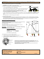
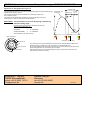
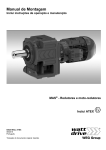
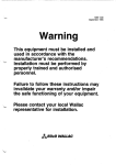
ENEMAC Operating instructions Safety couplings types ECA ECB (ECC)
mode of function
When the machine is operating normally the steel balls are pressed by the
disk spring into the cupped recesses located in the flange ring, thereby transmitting
the torque from the hub to the flange ring and vice-versa.
switching distance
bearing for belt pulley
ECA
overload
In the event of overloading the hub turns round in relation to the flange ring and
presses the balls out of the recesses back against the disk spring
- the coupling clicks over - (once per revolution in case of fixed point switching)
and actuates the proximity switch, which has to shut off the drive immediately.
The coupling is only designed to click over for a short period !
proximity
switch
steel balls
h2
hub
bushing
engage
After elimination of the disturbance, the coupling has to be rotated
- with low rotational speed or by hand and reengages automatically (audible) in the fixed point position.
The coupling now is operational, the adjusted disengagement torque is effective.
flange ring
adjustment nut
h1
disk spring
ECB
switch plate
technical data
ECA
1
3
6
16
25
40
63
75
100
130
250
400
ECB + ECC
3
6
16
25
40
63
100
250
400
torque range (adjustable)
0,9
3
6
16
25
45
75
75
130
130
250
400
TA max
(Nm)
TA min
(Nm)
0,5
1,2
2,5
6
10
20
30
30
50
50
100
160
–1
max. rotational speed
(min ) 3000 3000 3000 3000 3000 3000 2500 2500 2500 2500 2000 2000
thread of screws
h 2 6x
M3
M4
M4
M4
M5
M5
M6
M6
M6
M6
M8
M8
torque of hub screws
h 2 (Nm)
1
1,5
1,5
2,5
3
4
6
6
8
8
35
35
thread of flange ring
h 1 6x
M3
M4
M4
M4
M6
M6
M6
M6
M6
M6
M8
M8
max. screw position
i
(mm)
6
8
8
10
12
12
12
12
12
12
16
16
metal bellows data type ECC
(type ECC is no longer available)
max. shaft misalignment
lateral
(mm)
0,27 0,27
0,2
0,2
0,2
0,2
0,2
0,2
0,2
0,8
0,8
0,8
0,9
0,9
1,3
1,2
1,2
1,0
axial
±
(mm)
3
torsion resistance
(10 Nm/Rad)
5
5
21
33
33
54
66
108
164
lateral spring rate
(N/mm)
29
29
189
262
262
218
401
503
692
The torque data are valid for the tightening screws h 2 of the bushing only.
The screws h 1 for the pulley must be tightened with the usual torque !
Please take notice of the max. screw position i (into the flange ring)
installation instructions
general remarks
1. The kind of fit between bushing and shaft must be a sliding fit (e. g. H7/j6 or G7/k6).
The frictional connection will not be impaired by existing keyways.
2. During delivery the screws of the bushing are slightly tightened. To enable the hub slipping on the shaft, the bushing and it’s screws
have to been loosened.
3. The screws must be tightened cross-wise to avoid axial run-out of the coupling. Especially with type ECB a severe wobble will cause
tilting of the pulley and seizing up on the shaft end. In case of collision the pulley cannot rotate and the coupling cannot disengage.
Tightening torque of screws see Technical data.
4. dismounting
After unscrewing the 6 tightening screws the bushing is released from the hub by means of 3 draw-off screws
(see illustration to the right). If axial space is restrictive it is advisable to screw in the draw-off screws before
mounting the coupling and to counter check them against the hub.
5. emergency switching
In case of overload the drive must be turned off immediately by means of an emergency switching. A proximity
switch can be activated by the axial motion of the switch plate of the coupling and initiate the machine stop.
All couplings are designed for 250 overload cycles.
6. mounting in vertical axes of CNC machine tools
It must be taken in consideration that after disengagement the EC-coupling has a residuel torque so low that in most of cases it is
insufficient to prevent the descenting of the machine axle.
for safety couplings type ECA
7. The axial center lines of the belt pulley and the ball bearing of type ECA should be in
alignment, to prop the traction of the belt directly by the bearing (see illustration to the right).
8. The kind of fit between pulley and bearing must be a sliding fit (H7/h5).
Dimension k 2 must be machined within 0 trough +0.1 mm. The stop collar at left of the
outer race of the bearing must at least have 3 mm to guarantee the plane rest of both parts
(see illustration to the right).
for safety couplings type ECB
9. A pulley to be attached to type ECB must have a complete plane surface on the side of the coupling.
As well the ECB as the pulley are separately centered to the shaft thus an additional centering
between both is in no way tolerable.
ENEMAC Operating instructions Safety couplings types ECA ECB (ECC)
for safety couplings type ECC (type ECC is no longer available)
10. ATTENTION! The metal bellows of the ECC’s are made of thin stainless steel thus beeing susceptible to shocks.
Damage to bellows can result in an unserviceable coupling !
11. The ECC can compensate for shaft misalignments within certain limits
(= max. lateral shaft misalignment see Technical data).
ECC
It must be acted upon the following instructions to obtain the actual lateral shaft misalignment:
The set-up of the dial gauge is shown by the picture, i. e. fastening of the gauge to one side
(shaft 2) of the already mounted coupling and zero adjustment of the caliper.
A 360° turn of the complete measuring system and observation of the maximum reading.
The lateral shaft misalignment is half of this reading.
shaft 1
shaft 2
In case of a set-up without a mounted ECC the dial gauge has to fastened to shaft 2 and the caliper adjusted to shaft 1. Turning shaft 2
by 360° the maximum reading will include the amount of defect of form (=out of round), but this deviation can be neglected in nearly all
cases.
The complete 360° turn of the measuring system is essential !
12. Mounting of the ECC-coupling
The first step is to position the coupling loose on both shaft ends and then to tighten it to shaft 2. Possible axial tension of the bellows
must be released by turning one shaft end while stopping the other one. The bushing of shaft 1 may not be tightened before completing
this tension release. During mounting the bellows shall not be deformed too much. Permitted are 0.6 mm lateral and ± 1 mm axial.
Under operation conditions however the values of Technical data are valid.
adjustment of disengagement torque TA
operating range
characteristic curve
of disk spring
The disengement torque TA is continuously adjustable (without change the disk spring) !
Special torque ranges on request.
The couplings are pre-set by the manufacturer on assembly at about 70%
of the maximum torque.
setting range
switching
distance
MAX
The torque can be subsequently adjusted by turning the adjustment nut with a
sickle spanner. Loosen the Allen set screws beforehand !
Opposite to the common practice this results in the effect,
that turning the adjustment nut
clockwise
counter-clockwise
⇒
⇒
TA decreases
TA increases
torque TA
IMPORTANT ! The characteristic curve of the disk spring is diminishing
within the setting range !
MIN
spring distance
(see illustration to the right and foot)
released
plan surface
The really effective TA can only be measured precise, if
♦
♦
♦
coupling and belt-pulley or intermediate flange are assembled or
the measuring device simulates this assembly and
points 7 trough 9 of the Installation instructions are taken into consideration
arrangement of disk spring
range of adjustment
adjustment nut
conical hub
Allen set screw
marking
ENEMAC GmbH
The marking on the hub (see illustration to the left) must be between MIN and MAX in the
adjustment range (=greater part of the circumference of the adjustment nut).
By no means adjust torque below MIN, because in that case the disk spring will be blocked
during disengagement, and the coupling will not operate.
After adjustment the nut has to be fixed against turning by means of the Allen set srews
(fixed with LOCTITE 222 or similar).
63839 Kleinwallstadt
Daimler Ring 42
Germany
« +49 (0) 6022 7107-0
[email protected]
¬ +49 (0) 6022 22237
enemac.de
KW 10/12
ENEMAC Operating instructions Torque Limiters types ECE ECG ECH ECI ECR
mode of function
switching distance
When the machine is operating normally the steel balls are pressed by the
disk spring into the cupped recesses located in the flange ring, thereby transmitting
the torque from the hub to the flange ring and vice-versa.
proximity
switch
ECE
flange ring
overload
h
In the event of overloading the hub turns round in relation to the flange ring and
presses the balls out of the recesses back against the disk spring
- the clutch clicks over - (once per revolution in case of fixed point switching)
and actuates the proximity switch, which has to shut off the drive immediately.
The clutch is only designed to click over for a short period !
threaded pin as
axial fixation
in „L“ version
hub
engage
adjustment nut
After elimination of the disturbance, the clutch has to be rotated
- with low rotational speed or by hand and reengages automatically (audible) in the fixed point position.
The clutch now is operational, the adjusted disengagement torque is effective.
seat for
sliding
bearing
disk spring
steel balls
ECG/ECI
technical data
ECE ECG
ECI
torque range (adjustable)
TA max
TA min
max. rotational speed
thread of flange ring h
max. screw position
i
ECR (stainless steel)
torque range (adjustable)
TA max
TA min
max. rotational speed
thread of flange ring h
max. screw position
i
5
5
(Nm)
(Nm)
-1
(min )
6x
(mm)
16
16
25
25
40
40
63
63
100
100
200
200
315
630
315
630
900
900
5
10
16
25
40
63
100
200
315
315
630
630
900
2
4
7
10
16
25
40
80
140
140
280
280
400
3000 3000 3000 3000 3000 3000 2500 2500 1800 1800 1800 1800 1800
M5
M5
M6
M6
M6
M6
M6
M6
M8
M10
M8
M10 M10
6
6
8
8
8
8
12
12
15
15
15
15
15
50
(Nm)
(Nm)
-1
(min )
6x
(mm)
10
10
100
160
240
h
50
100 160
240
15
40
60
100
3000 3000 2500 2500
M6
M6
M8
M8
8
8
12
12
ECR
The screws h for the drive element must be tightened with the usual torque !
Please take notice of the max. screw position i (into the flange ring).
ECH (chain wheel integrated)
torque range (adjustable)
TA max
(Nm)
TA min
(Nm)
-1
max. rotational speed
(min )
5
16
25
40
63
80
140
200
400
630
900
5
16
25
40
63
80
140
200
400
630
900
2
6
10
16
25
32
56
80
160
280
400
3000 3000 3000 2800 2800 2500 2500 2000 2000 1500 1500
ECH
installation instructions
general remarks
1. The fit between the hub and shaft should be chosen as close sliding fit (e. g. H7/j6 or G7/k6).
Keyway according to DIN 6885 sheet 1.
2. For axial fixation (against displacement on the shaft) threaded pins are provided that clamp the hubs against the keyways.
An exception is the version „K“ in the types ECE/ECG and ECI, which are for example fixed by a stop collar and washer.
3. The maximum rotational speeds specified in the Technical data refer only to the respective clutch by itself.
If drive elements are incorporated that permit lower rotational speeds, these are obviously decisive,
(e. g. the maximum permissible chain speed).
4. Emergency switching
In order to protect the machine and clutch, the drive must be shut off in the event of overloading !
Normally the disk spring of the clutch activates, via the switching distance, a proximity switch arranged in axial direction and which
disconnects the motor power circuit.
for types ECE, ECG, ECI and ECR:
5. The drive element (e. g. pulley) is simply bolted onto the clutch, the torque being transmitted by friction.
6. ECE and pulley are both centred on the shaft and must not be additionally centred relative to one another by a fit bearing.
7. With type ECE the drive element (e. g. pulley) must have its own sliding bearing on the shaft, which supports the tractive force
of the belt. The clutch cannot absorb this force.
8. Points 6 and 7 apply as appropriate to types ECG, ECI and ECR. In this case the drive element is centred and mounted directly on the
clutch bearing instead of on the shaft. In order to have a lower sliding speed in the event of overloading, the sliding bearing is
incorporated in the drive element (is therefore not included in the delivery specification of the ECG, ECI or ECR).
9. The slide bearing clearance has to be < 0,03 mm.
For the types ECG, ECI and ECR we recommend the installation of the slide bearing SKF type GLYCODUR F.
The tolerance f 7 of the bearing is matched to these slide bearings.
10. With type ECE an adapter flange enables also small pulleys or chain wheels to be installed.
ENEMAC Operating instructions Torque Limiters types ECE ECG ECH ECI ECR
adjustment of disengagement torque TA
operating range
The disengagement torque TA is continuously adjustable (without change the disk spring) ! characteristic curve
of disk spring
Special torque ranges on request.
The couplings are pre-set by the manufacturer on assembly at about 70%
of the maximum torque.
setting range
switching
distance
MAX
The torque can be subsequently adjusted by turning the adjustment nut with a
sickle spanner. Loosen the Allen set screws beforehand !
Opposite to the common practice this results in the effect,
that turning the adjustment nut ...
clockwise
counter-clockwise
⇒
⇒
TA decreases
TA increases
torque TA
IMPORTANT ! The characteristic curve of the disk spring is diminishing
within the setting range !
MIN
spring distance
(see illustration to the right and foot)
released
plan surface
range of adjustment
arrangement of disk spring
adjustment nut
hub
Allen set screws
marking
ENEMAC GmbH
The marking on the hub (see illustration to the left) must be between MIN and MAX in the
adjustment range (=greater part of the circumference of the adjustment nut).
By no means adjust torque below MIN, because in that case the disk spring will be blocked
during disengagement, and the coupling will not operate.
After adjustment the nut has to be fixed against turning by means of the Allen set srews
(fixed with LOCTITE 222 or similar).
63839 Kleinwallstadt
Daimler Ring 42
Germany
phone +49 (0) 6022 7107-0
[email protected]
fax +49 (0) 6022 22237
enemac.de
KW 10/12