1
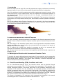
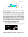
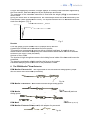
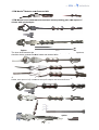
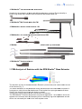
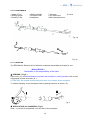
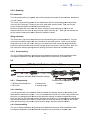
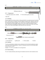
Extraction
ction Tools for Total Hip
ip Replacem
Replacements
EPM Mueller
ueller® Stem Extractor AU/AU2
/AU2, S/S2,
EPM Mueller® Modular Extractor
tractor Syste
System 2
„Kno
„Knockout
Tool for Joint Prosthesis“
CE, ISO 13485
FDA
DA Establishment
Establish
Registration Number: 3003759646
Patented in most
ost countrie
countries, USA Pat.Nr.5.534.006, USA Pat.Nr.
at.Nr. 8.603
8.603.100B2,
EP 0.645.127, DE 43.32.872 C1
Technic Documentation
Technical
Development of EPM Endo Plant Müller GmbH
Developm
Copyrig ©1993-2014 . All rights reserved
Copyright
EPM Endo
o Plant Mülle
Müller GmbH · Schleusen Str. 8, 63839
39 Kleinwall
Kleinwallstadt
Tel.:+49
+49-(0)6022/25419 · Fax: +49-(0)6022/25419
e-Mail: [email protected]
Ust - IdNr.:180825097,
IdNr.:18082
Registered Aschaffenburg,
g, HRB 8276
man
manager:
E.J.Müller MD.MDstom.
www
www.epm-mueller.de
1
Technical Documentation
Content:
1. Introduction
2. Definition of medical tasks
3. Finite-element model (FEM) analysis for revision with conventional extractors
3.1. Finite element (FEM), conditions and loads
3.2. Results and discussion
4. Principle and construction of the EPM Mueller® Stem Extractor
5. Measurement of the functional Prototype
6. The EPM Mueller® Extractor, the EPM Mueller® Modular Extractor System 2
6.1. EPM Mueller® Stem Extractor
6.2. EPM Mueller® Modular Extractor System 2
6.2.1. EPM Mueller® Modular Extractor system 2 components
6.2.2. EPM Mueller® Modular Extractor System 2 posibilities
7. FEM analysis for the revision of the EPM Mueller® Stem Extractor
8. Clinic use in Garmisch-Partenkirchen KKH with the EPM Mueller® Stem Extractor
9. User manual
9.1. EPM Mueller® hip stem Extractor
9.1.1. short description
9.1.2. components
9.1.3. handling
9.1.4. detachment
9.2. EPM Mueller® Modular hip stem Extractor MO1
9.1.2. components
9.1.3. handling
9.1.4. ddetachment
9.3. EPM Mueller® Knee prosthesis Extractor KN2
9.3.1. components
9.3.2. handling
9.3.3. ddetachment
9.4. EPM Mueller® Acetabular hemispherical- and Screw-cup Extractor C2
9.4.1. components
9.4.2. handling
9.4.3. ddetachment
9.5. EPM Mueller® Pin and sling Extractor PS2
9.5.1. components
9.5.2. handling
9.5.3. ddetachment
9.6. EPM Mueller® M6 hip stem Extractor M6
9.6.1. components
9.6.2. handling
9.6.3. ddetachment
9.7. EPM Mueller® Thread maker Set ™
9.7.2. components
9.7.3. handling
9.8. EPM Mueller® hook Extractor H
9.8.1. components
9.8.2. handling
9.8.3. detachment
9.9. EPM Mueller® Quick adapter with curettes, osteotomes planing and pans
9.9.1. components
9.9.2. handling
9.9.3. detachment
9.10. maintenance
10. Cleaning and sterilization
10.1. Preparation
10.2. Recommended course of action for returned goods / returns
10.3. Preparation for cleaning and disinfection
10.4. Manual and machine cleaning and disinfection
10.5. Checks and Care
10.6. sterilization
10.7. Storage of non-sterile and sterile instruments
11. Technical data
12. Spare parts
13. Warranty, Service
2
1. Introduction
Since its inception in the early 60’s, total hip replacement surgery has become enormously
important; today it is one of the most successful surgical interventions in orthopedics.
One of the problems in total hip replacement and joint replacement surgery in general, is the
limited survival time of the implants which have not reached the biomechanical qualities of
the natural hip joint. Today a survival time of 10 to 15 years is considered normal if no
complications occur.
After years of implantation time the devices loosen aseptically. This loosening is induced by
wear particles. A loose prosthesis causes pain, which makes a revision operation necessary.
(Fig. 1)
One of the problems during Revision Operations is the removal of the femoral component
from the femora. Even if the implant is loose and micro motion is possible, they are still fixed
by soft tissue and therefore hard to remove.
Fig. 1
Fig. 2
2. Definition of Medical and Technical Purposes
2.1. High, accurately directed forces have to be applied to the femoral component for short
periods of time so that the extraction impulse only acts upon the femoral component itself.
(Fig. 7)
2.2. The energy of the extraction impulse has to be so high that the connection between
implant and femora (i.e. cement femora) is terminated before the energy of the impulse is
transferred to the femora. (Fig. 5)
2.3. To achieve this, uniaxial force transfer is necessary as well as an extremely high
connection force between instrument and femoral component. (Fig. 4)
2.4. The force vector has to be as close to the longitudinal axis of the femoral component as
possible. (Fig. 4)
3. FEM-Analysis of Revision with Conventional Extraction Tools
To visualize the special relationships and magnitudes of force potentials, and to compare the
loads acting upon the cortical bone of the femora in revisions of the femoral component, a
finite element strain analysis of the femora while extracting a femoral component with
different extraction devices was performed.
3.1. Finite-Element-Modeling (FEM), Conditions and Loads:
For the Finite-Element-Analysis (FEA), two identical femora with two identical femoral
components were modeled. (Fig. 3,7). The femora were comprised of 3-D elements. The
femoral component outside of the bone and heads of the extraction instruments were
compiled of 2-D elements. For the calculations, the near-half symmetry of femora and
femoral components were used. At the ends of the heads of the extraction instruments a
ramp force profile of F=0 N at time t=0s to F=10 kN at t=30 ms was imprinted in axial
direction. The axial direction is parallel to the middle axis of the femora in the FEM. Therefore
this represents a best case for the conventional extraction instruments. (Fig. 3)
The femora is imbedded in 2-D elements, which represent the properties of the muscle
surrounding the bone. A strain-free condition is assumed at t=0. Fig. 3
3
Fig. 3
3.2. Results and Discussion
iscussion
To depict the strains inside the femurs and femoral components,
ts, the von
von-Mises-strains (s
EQV) were used. The
e FEA was performed in a transient mode. The diagram
diagrams 3 and 7 show
the von-Mises-strainss at maximal extraction forces at t=30 ms.
One can notice the non-homoge
homogenous distribution of strains inside
ide the fem
femoral component
when conventional extraction to
tools are used. (Fig. 3). One can
an deduct an
a asymmetrical
transfer of forces to the
he femora from
fr
this, which can only lead to a partial disconnection
disc
of the
implant from the surrounding
ounding tiss
tissue. Therefore, multiple applications
ons of the forces
fo
have to be
performed.
bution of th
the strains in the cortical bone, extraction w
with conventional
Looking at the distribution
tools causes high strains
rains on the whole (Fig. 3, ABC) and especially
ially high maximal
ma
strains in
the middle of the prosthesis
sthesis and a
at the lower end of the prosthesis.
s. (Fig. 3, D)
With the conventionall extraction tools, the force vector is not directed
ected along the longitudinal
axis of the femoral component
omponent - in the optimal case it is only parallel
rallel to this axis (Xp) - the
femoral component therefore jam
jams and is hard to remove. The energy impu
mpulse is conveyed
laterally to the femora.
Fractures of the trochantor
chantor or the
th shaft of the femora can occur.
cur. (ABC). A misalignment
between extraction vector
ector and th
the longitudinal axis of the prosthesis
esis can lead to injury of the
bone surrounding the prosthe
prosthesis, to fractures and associated lengthening
gthening of tthe surgical time
and anesthesia, increasing
asing of the risk of infection, etc.
4. Principle and Construction
onstruction of the EPM Mueller® Extractor.
Provide Axial force transfe
transfer and maximal clamping force.
Ensure the necessary
cessary cla
clamping force is transferred to the neck of the prosthesis via a
curved toolhead.
ad. (Fig. 4).
The size of the
e toolhead is minimized because of limited space
pace during surgery.
The instrument is handled
ndled outside of the surgical field.
(CAD
AD picture) F
Fig. 4
5. Measurements of Function
Functional Prototype
The prototype was measured
easured wit
with a special trial set-up and a Piezo-force
force sensor.
sen
The profile
of force application was register
registered to monitor change of force over time and
an calculate the
transferred impulse.
4
A force was applied by hand via a weight against an infinitely hard
ard base and
an registered by
the Piezo-sensor. Data
ta were acq
acquired by an oscilloscope and stored.
The prototype of the extraction instrument is fixed and the weight (800g)
g) is accelerated to
about 10m/s.
During the whole time
e of the exp
experiment, the oscilloscope storess the strain d
delivered by the
Piezo-sensor (strain proportional to force). The impulse transfer time t is calc
calculated from the
strain-time-diagram. (Fig. 5).
K r a ft s t o ß v e r h a lte n - „ F u m u “
Sp an n u n g in V
1
0
-1
-2
-3
-4
-5
0 ,0 0 8
0 ,0 1 0
0 ,0 1 2
0 ,0 1 4
Z eit i n s
Fig. 5
Results:
From the graph of force
rce transfer time
t
of t=500µs can be derived.
A peak force of 50kN can be calc
calculated for force transfer.
This peak force corresponds
sponds to a set-up with an infinitely hard base.
se. In practi
practical use an
elastic fixation exists and conseq
consequently the measurements stated above will not
n be attained.
Duration of the force:: 0,5ms (=0,0
(=0,0005s)
Amount of force: 50Ns
The impulse is high enough
nough to ov
overcome the holding forces inside of the bone and loosen the
prosthesis.
The clamping mechanism
nism reliably transfers the force to the implant.
Calculated clamping force at the neck of the prosthesis is 30kN.
6. The EPM Mueller® Stem Extractor
E
EPM Mueller® Extractor AU -with open head on the side and one
ne sliding sp
spacer, proper
also for stems with fixed
xed heads (monobloks)
(
Fig. 6a
with closed head and single sliding spacer
EPM Mueller Extractor S -with
®
Fig. 6b
EPM Mueller Extractor AU-S
S with 2 exchangeable heads (open AU+
+ closed
close S) and one
sliding spacer
®
Fig. 6c
6
2, geschlossene Spannrahmen und drei Druckba
Druckbacken (A, B, C)
EPM Mueller® Extractor AE2
EPM Mueller® Extractor PN-AU
AU, PN-S, with adapter for pneumatic
Fig. 6d
5
A
revisions, with closed
sed head, ssingle slider
EPM Mueller® Extractor SA for Antero-access
spacer and slider bar.
Fig.6e
ch
by axial force transfer and exceptional
excep
clamping
The EPM Mueller® Extractor is characterized
mechanism.
The necessary clamping
ing force is transferred to the implant neck byy a curved ttoolhead.
The size of the tool head
ead is adapt
adapted to space restrictions dictated by the surgical
surgi
procedure.
The EPM Mueller® Extractor is handled
ha
outside of the surgical field.
The EPM Mueller® Extractor
xtractor AW
AW6 has been in clinical use since 1993, the EPM Mueller®
Extractor AE ( ABC Extractor ), the EPM Mueller® Extractor AU since 1999 and the EPM
Mueller® Extractor S since 2004,
2004 the EPM Mueller® Extractor PN since
ince 2007,
200 the EPM
®
Mueller Modular Extractor
xtractor System
Sys
1 since 2009.
®
We launch 2014 the new EPM Mueller
M
Extractor AS for Anteriorr approach rrevisions and
the EPM Mueller® Modular
odular Extra
Extractor System 2.
The EPM Mueller® Extractor can be fixed to the exposed neck of the prosthes
prosthesis with a few
easy movements and the prosthe
prosthesis can be removed with limited time and force
for
requirements.
The EPM Mueller Extractor
tractor can b
be removed from the prosthesis after
fter extractio
extraction via an easy
snap-lock mechanism without a
additional tools. It can be disassembled
bled and as
assembled easily
and fits into a standard
rd surgical tr
tray.
Easy cleaning and sterilization
erilization ar
are assured; the instrument is fully autoclavab
autoclavable.
6.2.1. EPM Mueller® Modular Extractor System 2 components:
- Hip Stem Extractor AU-S2)
- Pneumatic Shaft Extractor
- Extractor approach jaws for modular
mod
stems MO1
- Knee stem Extractor approach KN2
- Pan Extractor approach C2
- Pin and Loop Extractor approach
approac PS2
- Screw Extractor approach M6 threaded makers Set ™
- Ruined screw remover set SR
- Quick adapter with curettes,, planing and pan osteotomes
- Chipping Extractor approach H2
- Sterilization basket with silicone lid supports and instruments
We developed 2014 EPM Muelle
Mueller® Modular Extractor System 2 based
ased on the EPM Mueller®
hip stem Extractor. Newly
ewly developed
develo
attachments allows the extraction
action of various
var
prostheses
such as modular neckless
kless hip, lar
large head, knee, acetabular hemispherical
ispherical or screw cups,
pins, stuck drills and ruined screw
screw.
Together with the EPM
M Mueller® stem Extractor AU-S2 the Modular
ular Extracto
Extractor system2
attachments provide a complete solution for prosthesis revision problems..
6.2.2. EPM Mueller® Modular Extractor
Ex
System 2 -use possibilities:
- EPM Mueller® stem Extractor S2, or AU2
- EPM Mueller® Pneumatik
umatik Sha
Shaft PN2 ( for Woodpacker )
6
- EPM Mueller® Modular stem Extractor MO1
- EPM Mueller® Knee shaft Extractor
Extr
KN2 with extra spreading jaws, with option of
chisels with quick adapter
Option:
The knee shaft extractor jaws can also be used for tibial component, large head hip stems,
shoulder stems, modular
ular stocked heads and stocked drills.
- EPM Mueller® hemispherical
erical and Screw cup Extractor C2 with extra spreading
eading jaws and housing
handle, with option of cup osteotome
osteoto
and quick adapter and hook attachment
option
7
- EPM Mueller® stem Extractor M6 attachment
Suitable for the extraction of stems
stem with M6 threaded entry (such as Zimmer-shafts)
Zimmer
or
broken long shafts after made of a M6 thread with M6-thread maker set.
- EPM Mueller® M6-Thread
hread maker-Set
mak
TM
- EPM Mueller® Ruined
ed screw remover
r
SR
- EPM Mueller® Pin and Sling-extractor
Sling
attachment PS2
- EPM Mueller® Quick-Adapto
Adaptor with curette, chisels and cup osteotome
steotome
- EPM Mueller® Hook attachment
attachme
®
7. FEM-Analysis
is of Revis
Revision with the EPM Mueller Stem Extractor
E
Fig.. 7
The direction of force of the EPM Mueller® Extractor (normal case)) lies in the m
middle axis XY
of the femora (Fig. 7).
The strain distribution
n in the pros
prosthesis during extraction with the EPM Muelle
Mueller Extractor is
homogenous, which favors the de
detachment of the implant from spongiosa
ongiosa and soft tissue.
Strain in the cortical bone is low a
and shows no peaks.
Therefore the risk of fracture of th
the cortical bone is minimized.
The EPM Mueller® Extractor is optimized
op
for practical application. The extracti
extraction forces are
applied to the relevantt sides, the clamping force is extremely high and depend
dependable and the
device can universally
ly be used fo
for the most implant necks.
8
8. Surgical Use in Garmisch-Partenkirchen-Hospital of the EPM
Mueller® Stem Extractor
The EPM Mueller® Extractor has been in clinical use in Garmisch-Partenkirchen-Hospital
since October of 1993. At the time of writing, EPM Mueller Extractor has been used during
over 600 total hip revision operations in the hospital. A large number of femoral components
have been successfully removed; with only a few was extraction not possible. These failures
were primarily in the experimental phase, using the prototypes (AW3/4); the geometry of the
instrument head has since been changed accordingly.
EPM Mueller® Extractor AU has been in clinical use since 1999.
The remaining failures were due to a maximal stability of the implant in the surrounding
bone, meaning an absence of loosening. Stable implants cannot be removed by an
extraction tool alone.
To date no complications, for example bone fractures, have been noted.
Handling has proven to be safe and easy. The posture approach usually favored in
GarmischPartenkirchen often leads to restricted available space at the operative site; the
limited size of the toolhead and the handling of the instrument outside of the surgical field
have therefore proven extremely useful.
The surgical personnel have praised easy handling, cleaning and sterilization of the EPM
Mueller® Extractor. All parts of the EPM Mueller® Extractor can be assembled and
disassembled with ease and safety.
The space needed for storage is minimal and since the instrument can be used universally it
is not necessary to maintain a large inventory of extraction devices
9. Use Instructions
9.1.
EPM Mueller® Stem Extractor AU/AU2, S/S2
9.1.1. DESCRIPTION
The universal extraction device for total hip replacement femoral components EPM Mueller®
Extractor is a modern surgical instrument which addresses problems arising through
the increasing number of revision surgeries in total joint replacement.
It ensures secure, efficient, low cost and correct handling. Ergonomic aspects concerning the
design of the grip and handling have been incorporated into manufacture as a result of
ongoing feedback and development.
Key part of the instrument is the patented clamping mechanism and head with exceptional
clamping force ensuring a secure connection between the instrument and almost all implant
necks or tapers, commercially available today.
The applied force is transferred to the prosthesis’ neck axially, thereby avoiding dangerous
eccentric leverage.
9
9.1.2. COMPONENTS
1 Head of Tool
2 Sliding Spacer
3 Guiding Tube
4 Striking Weight
5 Pressure Rod
6 Handpiece
7 Jamcase
8 Pin with screw
9 Bolt with plasticinset
10 Lever
Fig. 1a
Fig. 1b
Variant AE ( ABC extractor )
9.1.3. HANDLING
The EPM Mueller Extractor AU is delivered completely assembled and ready for use.
( NON STERILE! )
Sterilization is the responsibility of the User.
OPENING ( Fig 2 )
Open lever ( 1 ) and thread between jamcase and handpiece ( working thread ) with circular
movements reverse clockwise ( 2 ).
ATTENTION: the threads at the guiding tube have to be always closed complete!
To enable clamping, move the spacer back by putting pressure on spacer ( 3 ).
Fig. 2
APPLICATION and CLAMPING ( Fig.3 )
Slide ( 1 ) tool as far as possible over the neck of the prosthesis.
10
Note: To use the instrument safely and effectively, the orientation of the prosthesis has to
be analyzed carefully and the EPM Mueller® Extractor has to be APPLIED AXIALLY.
For clamping, rotate ( 2 ) the handpiece with the opened lever( at 90° to the axis) at the
distal-end clockwise until resistance is felt.
Close ( 3 ) the lever to attain maximal clamping force.
ATTENTION: USE NO ADDITIONAL TOOLS (HAMMER)
Fig. 3
EXPLANTATION ( Fig.4 )
The weight is placed at the end of the guidance tube closest to the prosthesis, and
is then moved forcefully towards the distal end of the tool, impacting on the base of
the handpiece.
Fig. 4
Attention:
Do not use additional instruments with the EPM Mueller Extractor! ( as HAMMER )
DETACHMENT ( Fig.5a, 5b )
The extracted implant is removed from the tool with the same steps explained
under OPENING of the instrument. (Fig. 2 )
9.1.4 Disassembling
To disassemble look at picture 1, 5a and 5b.
• 1. Completely unscrew (reverce clockwise) lever assembly ( jamcase ) (Fig 5a) of
handpiece
• 2. Remove the pin screw, with the Allan key 3 delivered, than lever, thereafter bolt with
plasticinset with a narrow instrument ( presure rod can be used )
• 3. Extract presure rod
• 4. Detach handpiece by unscrewing completely from the guiding tube
• 5. Slide off the striking weight
• 6. Remove sliding spacer through rectangular space at the instrument head
• 7. Remove guiding tube by unscrewing completely from the instrument head
ATTENTION: use the bolt always with the plasticinset together!
11
Fig. 5a
ATTENTION: NOTE CORRECT ORDER OF slider spacers (A, B, C)! at the AE variant (Fig. 5b)
Fig. 5b
9.2
EPM Mueller® Modular-stem extractor
ctor MO1
MO
9.2.1. Components
2a 2b 2c
1
3(5)
4
10
6 7(9)8
EPM Mueller® Modular-stem Extractor
Extract MO1
1 body
1b body pin screws
2a, 2b, 2c Moveable Set
3 guiding tube
4 stroke weight
5 pressure rod
6 lever
7 jamcase
8 pin with screw
9 bolt with plastic insert
10 handle
9.2.2. Handling
Place the spreading jaws set in the opening of the body and secure it with the 2 body pin
screws using the Allen key No.3. Turn the Extractor jamcase from the handle first almost
completely out and then
en screw the guiding tube of the extractor into
to the thread of the jaws
body until it stops. Now, by turning
turnin the lever together with the jamcase, the spreading
sp
jaws
will get off and catch the modular stem.
The jaws are always hold by your hand on the body in the closed position
Stem knocking out: Adjust the
t spreading jaws to the prosthetic modular neck cavity and
insert it till stops.
Turn the lever is in a vertical position to Extractor, including
includ
jamcase
until you pinch the prosthesis firmly, finaly press the lever to the handle. Now you can extract
the prosthesis by striking
king movem
movement of the hammer weight towards Extractor handle.
9.2.3. Disassembling
The unit is disassembled by unscrewing
unsc
the threaded connections without additional tools,
excepting the jamcase
e and the ja
jaws body, which is further decomposed into parts
p
using a
supplied Allen key
12
9.3
®
Knee extractor KN2
EPM Mueller
Mu
9.3.1. Components
2a
1b
1
3(5)
4
10
6 7(9)8
Option:
2b
11a
11b
12b(12c)
12a
12e
12d
EPM Mueller® Knee Extractor KN2 with clamping and spreading jaws + Option:
Option 2 chisels with
quick adapter with plate or pneumatic
pneum
coupling
1 jaws body
1b body pin screws
2a clamping jaws set
2b spreading jaws set
3 guiding tube
4 striking weight
5 pressure rod
6 handle
7 jamcase
8 pin screw
9 bolt with plastic insert
10 lever
11a chisel R
11b chisel Z
12a Quick adapter shaft
12b Quick adapter cover
12c Quick Adapter spring
12d Quick Adapter Plate
12e Quick Adapter
dapter pneumatic coupling
9.3.2. Handling
Place the two pressure jaws into the opening of the housing and secure it with the 2
mounting screws using the Allen key No.3. Turn first the extractor jamcase from the handle
almost completely out and then screw
s
the guide tube of the extractor into the thread of the
jaws body until it stops. Now you can compress or release the jaws as desired by turning the
lever including jamcase into the handpiece.
h
Your hand on the body
dy holds the jaws always in the wide-open position, or at the spreading
jaws in the closed position.
Prosthesis knock out:
Adjust the opening off the jaws to the prosthesis outside dimension
n to be extra
extracted ( by the
spreading jaws adjustt to the insid
inside dimension ). The adjustable clamping
lamping jaws can clamp
objects of 5-110 mm ( at spreading
spreadin jaws of 18 – 80 mm ).
Turn the lever, which is in a vertic
vertical position for Extractor, to clamp
p firmly the prosthesis,
p
then
press the lever to the handle. Now you can extract the prosthesis by striking
ing movement
m
of
the hammer weight towards
owards Extra
Extractor handle.
9.3.3. Disassembling
unsc
the threaded connections without additional tools,
The unit is disassembled by unscrewing
excepting the jamcase
e and the ja
jaws body, which is further decomposed into parts using a
supplied Allen key
13
9.4
EPM Mueller® HemisphericalHemis
and screw-cup extra
xtractor C2
9.4.1. Components
2a
1b
1a
3(5)
4
10 6 7 ( 9 ) 8
1c
2b
Option:
11c
11c
12b(
12b(12c)
12a
12d
12e
EPM Mueller® Hemispherical
ical and screw
s
cup extractor C2 with clamping and
d spread
spreading jaws
Option: 6 cup osteotome, quick adapter with plate or pneumatic coupling for Woo
Woodpacker
1a body
1b body pin screw
1c body handle
2a clamping jaws
2b spreading jaws
3 guiding tube
4 striking weight
5 pressure rod
6 Handle
H
7 jamcase
8 pin screw
9 bolt with plastic insert
10 lever
11c cup osteotome
12a quick adapter
adapte shaft
12b quick adapter
adapt cover
12c quick Adapter
Adapt spring
12d quick adapter
adapt plate
12e quick adapte
dapter pneumatic
9.4.2. Handling
Place the two pressure jaws into the opening of the body and secure it with the
th 2 body pin
screws using the Allen key No.3.
Turn the extractor jamcase from the
t handle first almost completely out and then screw the
guiding tube of the extractor into the thread of the body until it stops. Now you can compress
or release the jaws ass desired by turning the lever including jamcase
ase into the handle. The
jaws are held by your hand on the body always in the wide-open, or at the spreading
spr
jaws in
the closed position.
ith clamping
clampin jaws:
Cup knock out with
Adjust the opening off the jaws to the cup outside dimension and set the jaw tips
perpendicular to the plane of the cup. Beat the jaws by the striking weight,, until
un the jaw step
abut the acetabular rim. Now turn the lever in a vertical position to extractor
xtractor, with the
jamcase until you pinch the cup firmly, then press the lever on the handle. Now you can
extract the cup by striking
iking movement
movem
of the hammer weight towards extractor
xtractor handle.
14
re
of the cup cup osteotome matching closely
c
the size
In a press-fit cup use after the relaxation
of the cup to remove bone and soft
so tissue contacts remains on the
e cup to avoid
avo bigger tissue
damages.
Hemispherical cup
p knock ou
out with spreading jaws:
Adjust the opening off the spreadi
spreading jaws to the cup inside (you have
ave to place the jaws to
catch favorable places). Now turn the extractor lever in a vertical position,, including jamcase
until you clamp the cup firmly,, then press the lever to the handle.
Now you can extract the cup by striking movement of the striking weight towards
towa
extractor
handle. In a press-fit cup use after the mobilisation cup osteotome matching closely the size
of the cup to remove bone and soft
so tissue contacts remains on the
e cup to avo
avoid bigger tissue
damages.
spreading jaws:
Screw-cup knock out with s
First mount the body handle on the
th side of the body and turn the handle until it stops. Adjust
the opening of the spreading
reading jaws to the cup inside. Now turn the extractor lever in a vertical
position, including jamcase until you clamp the cup firmly, (you have
ve to place the jaws to
catch favorable places), then press
pre the lever to the handle.
Now you can unscrew the cup by turning it anti-clockwise with the body handle.
handl
9.4.3. Disassembling
The unit is disassembled by unscrewing
unsc
the threaded connections without additional tools,
excepting the jamcase
e and the ja
jaws body, which is further decomposed into parts
p
using a
supplied Allen key.
9.5.
EPM Mueller® Pin and sling extractor
ctor PS2
PS
2
2a
1a
3
4
1
6
Pin and sling eextractor PS2
Pin and Sling extrac
xtractor Attachment
9.5.1. Components
1 Pin and sling extractor shaft
haft
1a cover
2 pin chuck for 1-2, 3-4 and 5-6mm
6mm diameter
2a metal l sling 120mm
3 guide tube
4 striking weight
6 Handle
15
9.5.2. Handling
Pin extractor:
Turn the guiding tube (3)
3) together
togethe with striking weight and handle in the Extractor
Extra
attachment
(1) until it stops.
The cover (1a) should be placed on the attachment with the unthreaded part forward and
cover the pin chuck part. First, turn the cover tube back onto the shaft. Then turn
t
the pin
chuck counterclockwise to the shaft-end
sh
thread firmly.
Now turn forward the cover over the chuck. Insert the chuck opening on the pin
p to be
extracted and turn the cover so long
lo until you catch firmly the pin. . Now you can
c extract the
pin by hammer striking
g movemen
movement direction extractor handle.
Sling extractor:
The cover tube (1a) should be placed
pla
with the thread-free part to the attachment.
attachm
Turn the
cover tube toward the shaft until the
t 2 recesses in the shaft are free. Hook one end of the
sling and cover it with the cover.
cover Now you can attach the other end
d of the sling around the
part to be removed and hook it into
in the second recess and cover it with the cover. Now you
can extract the hooked part by hammer
ha
striking movement direction Extractor handle.
9.5.3. Disassembling
The unit is disassembled by unscrewing
unsc
the threaded connections without additional tools.
A complete separation from the extractor attachment is performed
d in reverse order.
.
9.6
®
EPM Mueller
Mu
stem extractor M6
2
1
3
4
6
Extractor M6 with 2 M6 extractor screws
9.6.1. Components
1 M6 Extractor attachment
hment
2 M6 screw
Extractor M6 attachment
attach
3 guiding tube
4 striking weight
6 Handle
9.6.2. Handling
Turn the guide tube off the extract
extractor with the handle and striking weight
eight in the thread of the
M6 Extractor attachment
ent till stop. Turn on the attachment screw one
ne of the 2 M
M6 screws until
they stop. (by damaging
ing the threa
thread at the extraction having to change
nge only the M6 screw).
Now you can turn the extractor in
into the thread on the shaft (or in the manuf
manufactured M6 thread
with the thread makerr Set TM on a broken shaft).till stop and extract
act the shaft or the broken
shaft part by striking movement o
of the hammer weight direction extractor
xtractor hand
handle.
9.6.3. Disassembling
The unit is disassembled by unscrewing
unsc
the threaded connections without additional tools.
A complete separation from the Extractor attachment is performed
d in reverse order.
16
9.7
EPM Mueller
Mue ® thread maker set TM
1
M6 thread
threa maker set
2
9.7.1. Components
3
1. M6 thread maker
er with T han
handle
3. Thread makers guide with handle
2. M5 drill
9.7.2. Handling
Place the guide to the broken shaft site. Bring the M5 drill in the guide
uide tube up to the broken
point. The first mark on the drill is now on the edge of the guide tube. Start now
no to drill up to
the second mark reaches
ches the edg
edge. The 2 markers are 10 mm apart. After removal
rem
of the
drill, the guide tube and
nd thorough rinsing, you can make the M6 thread with the
th thread
maker. By twisting movements
ovements an
and repeated rinsing you create about 8 mm thread length.
Now you can screw the M6 extra
xtractor and extract the stem broken part.
9.8
®
EPM Mueller
Mu
hook extractor H2
1
3
4
6
Hook extractor H2
Hook extractor attachment
ttachment H2
9.8.1. Components
1. hook attachment
3. guiding
guidi tube
4. striking weight
6. handle
9.8.2. Handling
Turn the hook attachment
ment to the extractor guiding tube with the handel and striking weight
until it stops. After hooking the item,
ite remove it by striking movement of the striking weight
towards extractor handle.
Caution: The hook-tip can break off at to strong shocks!
9.8.3. Disassembling
The unit is disassembled by unscrewing
unsc
the threaded connections without additional tools.
.
17
9.9
EPM Mueller® Curette,
Cure
chisel, cup osteotome with quick
adaptor
ptor with p
plate and with pneumatic coupling
couplin
11d
11e
11c
11a
12b(12
12b(12c)
12a
11b
11
12d
12e
EPM Mueller® 2 curette, 2 chisels and 6 cup osteotome, quick adapter plate or pneumatic
pneu
coupling
for Woodpecker
9.9.1. Components:
11a chisel R
11b chisel Z
11c cup osteotome
11d curette S
11e curette L
12a quick adapter shaft
12b quick adapter cover
12c quick adapter spring
12d quick adapter plate
12e quick adapter pneumatic
atic coupling
9.9.2 Handling
Pull the cover back and
nd put the curette, chisel or osteotome into the
he recess of the quick
adapter shaft and let the cover off. The spring under the cover pushes it back to the closed
position.
9.9.3 Disassembling
Remove the curette, chisel or osteotome from the quick connector. Pull then the
t cover
completely until it stops, then turn it to the right and slide off the sleeve from the
th shaft. Now
you can remove the spring. At the other end of the shaft rotate the plate or the pneumatic
coupling from the shaft.
18
10. CLEANING and STERILIZATION
The new instrument: has to be cleaned up and disinfected before sterilisation.
10.1 Preparation
Brand new instruments and those returned from repair must be removed from their
transportation packaging before storing and / or inclusion in the instrument usage and
processing cycle.
10.2 Storage
Store it at room temperature in dry rooms. Condensate may cause subsequent corrosion
damage.
Never store it near chemicals such as active chlorine which emit corrosive vapors.
To avoid mechanical damage during processing, store it from the beginning in suitable racks
or retainers.
Before using, they must be sent through the entire processing cycle in the same manner as
used instruments.
The reprocessing comprises:
- Preparation ( pretreatment, collecting, precleaning and taking the instrument apart.
- Cleaning, disinfecting, rinsing, drying
- Visual inspection of clearness and acceptable condition of material
- Care and repair where required
- Functional test
- Marking
- Packaging and sterilization, approval for reuse and storage
Validated cleaning, disinfecting and sterilization processes, supplemented by defined
configurations for loading the washers/disinfectors and sterilizers are an indispensable
prerequisite for quality assurance.
Automated reprocessing with thermal disinfection and steam sterilization should be
preferred.
Use correct water quality!
When using softened water, especially when applying thermal disinfection in the final rinse,
anodized aluminium surfaces might be subject to attack due to an increased pH value.
Using demineralised water for steam sterilissation, limit values for feed water quality
conforming to EN 285 and ISO 17665 are required.
We recommend using demineralized water for the final rinse for the following reasons:
- No spoting
- No increase in concentration of corrosive constituents, e.g. chlorides
- No dried crystalline residues which could have a negative effect on the downstream
sterilization process
- Protection and stabilization of anodized aluminium surfaces
10.3 Returned instruments
Only if the instruments have been cleaned, disinfected, dried and have been declarated
hygienically safe
10.4 Cleaning and Disinfecting
Any residues should be removed.
Never immerse stainless steel instruments in a physiological salt ( NaCl ) solution, it leads to
pitting and stress corrosion cracking.
19
The passive layer of brand new instruments is necessarily still thin and so these instruments
tend to critical treatment conditions than are older used instruments.
Avoid long intervals between use and treatment for reuse.
For manual cleaning, active non-protein-fixing cleaners with or withaut antimicrobial effect
and/or enzymes are to be used.
Regarding detergents and desinfectants, the manufacturer`s instruction concerning
concentration, temperature and exposure time should always be strictly followed!
Use soft, lint-free cloths or towels, plastic brushes or cleaning guns for cleaning.
To prevent water spots (spotting), a final rinse using fully demineralised water is
recommended. After this the instrument must be dried carefully immediately.
By machine-based cleaning, only validated machine cleaning and desinfecting processes
( DIN EN ISO 156883 and national guidelines) should be used.
10.5 Check and care
Instruments must be checked visually – tactile and be macroscopically clean.
Maintance means targeted application of a lubricant milk to the joints, threads or friction
surfaces of instruments. This prevents metal on metal friction and therefore constitutes a
preventive measure against friction corrosion.
Requirements for care agents:
- Paraffin/white oil based, in accordance with the current European or United States
Pharmacopeia
- Biocompatible
- Suitable for steam sterilization and vapor permeable
Instruments must not be treated with care agents containing silicone oil.
The proper functioning of the instruments must be assured by testing.
Apply instrument oil to tube, rod and screws periodically to minimize wear friction.
10.6 Packaging
International standard EN ISO 11607 1 and 2 apply to packed items requiring sterilization.
It must be possible to mark and identify the package with information such as:
- Sterilisation date
- Packer
- Expiry or “use before” date (if date has been defined)
- Contents
10.7 Sterilisation
It is important to use only sterilisation methods and sterilizers that allow validated sterilization
processes conform national guidelines.
Sterilisation accessories and packaging materials must be selected in accordance with the
items to be sterilised as well as with the sterilisation method used.
Steam sterilization is the method of choice and is performed with saturated steam, usually at
134°C.
Use validated steam sterilization processes in accordance with ISO 17665, EN 554 (or DIN
58946 Part 6 in Germany )
10.8 Sterile storing
To guarantee the sterility of instruments until they are used on the patient, germ-tight
packaging is absolutely essential.
Further requirements for the protected storage of sterile supplies and the prevention of
corrosion damage include a dust-free and dry environment and the prevention of
temperature fluctuations.
20
11.TECHNICAL DATA
11.1. EPM Mueller® stem extractor S2, or AU2
· Tapers: Æ 8 – 16 mm
· Striking weight: 1.0 kg (2.2 lb)
· Total weight: 2,2 kg(4.84 lb), 1,2 kg (2.4 lb) ( PN Variant )
· Total length: 550mm (21.7 inches)( Standard ), 620mm (25 inches)( long ), 350mm ( PN )
· Hitting distance: 205mm (8.1 inches) standard; 275mm (8.8 inches) long
11.2. EPM Mueller® modular-stem extractor MO1
· Inside modular neck : Æ 8-10mm / Æ 10-17mm
· Striking weight: 1.0 kg (2.2 lb)
· Total weight: 2,65 kg(5.83 lb), 1,35 kg (2.97 lb) ( PN Variant )
· Total length: 560mm (22.1 inches)( Standard ), 630mm (25 inches)( long ), 360mm ( PN )
· Hitting distance: 205mm (8.1 inches) standard; 275mm (8.8 inches) long
11.3. EPM Mueller® Knee Prosthesis extractor K2
· Prosthesis dimensions : 7 - 110mm
· Striking weight: 1.0 kg (2.2 lb)
· Total weight: 2,65 kg(5.83 lb), 1,35 kg (2.97 lb) ( PN Variant )
· Total length: 590mm (23.3 inches)( Standard ), 660mm (26 inches)( long ), 360mm ( PN )
· Hitting distance: 205mm (8.1 inches) standard; 275mm (8.8 inches) long
11.4. EPM Mueller® acetabular hemispheric- and screw-cup extractor C2
· Cup outside dimension Æ 38 - Æ 74mm
· Striking weight: 1.0 kg (2.2 lb)
· Total weight: 2,65 kg(5.83 lb), 1,35 kg (2.97 lb) ( PN Variant )
· Total length: 590mm (23.3 inches)( Standard ), 660mm (26 inches)( long ), 360mm ( PN )
· Hitting distance: 205mm (8.1 inches) standard; 275mm (8.8 inches) long
11.5. EPM Mueller® Pin and sling extractor PS2
· Pin size : Æ 1-2, 3-4, 5-6mm
· Sling length 120 mm
· Striking weight: 1.0 kg (2.2 lb)
· Total weight: 1,9 kg(4.18 lb), 0,9 kg (2 lb) ( PN Variant )
· Total length: 550mm (21.7 inches)( Standard ), 620mm (25 inches)( long ), 350mm ( PN )
· Hitting distance: 205mm (8.1 inches) standard; 275mm (8.8 inches) long
11.6. EPM Mueller® Hook extractor H2
· Striking weight: 1.0 kg (2.2 lb)
· Total weight: 1,65 kg(3.63 lb), 1,2 kg (2.64 lb) ( PN Variant )
· Total length: 530mm (20.9 inches)( Standard ), 600mm (23.7 inches)( long ), 360mm ( PN )
· Hitting distance: 205mm (8.1 inches) standard; 275mm (8.8 inches) long
21
12. Supply and Spare
pare parts
1001.15.AU-S2.PN.KN2.C2.MO.
N2.C2.MO.PS2.M6.TM.SR.QP-CUC.QH-CO.H2.BE
EPM Mueller® Modular extractor system
ystem 2
1001.7.AU-S2
EPM Mueller® Stem Extractor AU-S2
1001.5.AU2
EPM Mueller® Stem Extractor AU2
1001.6.S2
EPM Mueller® Stem Extractor S2
1001.8.PN.AU; PN.S
EPM Mueller® Stem Extractor PN.AU, orr PN.S
PN.
1001.15.3.KN2
EPM Mueller® Knee Extractor K2
1001.15.4.C2
EPM Mueller® Hemispheric- and Screw-cup
cup Extractor C2
1001.15.5.MO
EPM Mueller® Modular- Stem Extractor MO1
1001.15.6.PS2
EPM Mueller® Pin and sling Extractor PS2
1001.15.7.M6
EPM Mueller® Extractor M6
1001.15.8.TM1
EPM Mueller® Thread maker TM
1001.15.9.DSR
EPM Mueller® Damaged screw remover DSR
1001.15.10.QP-CUC
EPM Mueller® Quick adaptor with pneumatic
neumatic co
coupling
curettes and chisels QP-CUC
1001.15.10.QH-CO
EPM Mueller® Quick adaptor with hammer
mmer plate and
cup osteotome
steotomes QH-CO
1001.15.11.H2
EPM Mueller® Hook extractor H2
1015.15.12.BE
Baske with lid and silicone holder, (62/24/7) BE
Basket
EPM Mueller® Modular Extractor
Extrac
System 2
Item no.:
12.1 Slap hammer and pneumatic
pneuma extractor shaft
1001.2.5.AU Head AU
1001.2.6.S
Head S
1001.2.04.U Slider spacer U
1001.2.17.ST2 Guiding tube ST2
ST
1001.2.17.L2 Guiding tube L2
L
1001.2.15.ST Pressure rod ST
22
1001.2.15.PN Pressure rod PN
1001.2.09.N Striking weight 1000g
100
1001.2.11.ST2 Handel ST2
1001.2.11.PN2 Handel PN
1001.2.12.02.ST Jamcase ST2
1001.2.12.PN
Jamcase PN
1001.2.07.2
Bolt with plasticinset
plasticin
1001.2.13.2
Pin screw
1001.2.13.A2.5-3 Allan key
1001.2.14.
Lever
ttachment 1001.15.3
12. 3 Knee Extractor attachmen
1001.15.2.3.B
Body
1001.15.2.3.S
Pin screw
1001.15.2.3.L
Knee clamping jaw left
1001.15.2.3.R
Knee
ee clamping jaw right
1001.15.2.3-4.L
Knee
ee and cup spreading jaw left
1001.15.2.3-4.R Knee and cup spreading
s
jaw right
nd screw cup Extractor attachment
12.4 Hemispheric-and
1001.15.2.3.B2
Body 2
1001.15.2.3.S
Body
dy pin screw
1001.15.2.3.G
Body
dy handle
1001.15.2.4.L
Cup
p clamping ja
jaw left
1001.15.2.4.R
Cup clamping jaw
ja right
1001.15.2.3-4.L
1001.15.4
Knee
ee and cup spreading jaw left
1001.15.2.3-4.R Knee
ee and cup sspreading jaw right
12.5 Modular-shaft Extractor spreading attachment
23
1001.15.5
1001.15.2.5
shaft Extractor
Ex
spreadingjaws set
Modular-shaft
1001.15.2.5.FJ
Modular
dular fix jaw
1001.15.2.5.MJ
Modular mobile
obile jaw
1001.15.2.5.MP Modular
dular mobile piece
1001.15.2.5.S
jaw pin screw
12.6 Pin and sling attachment
1001.15.6
1001.15.2.6.B
Attachmentt shaft
s
1001.15.2.6.C
Shaft cover
1001.15.2.6.P2
Pin chuck 1-2mm
1
1001.15.2.6.P4
Pin chuck 3-4mm
3
1001.15.2.6.P6
Pin chuck 5-6mm
5
1001.15.2.6.S
Metall sling 120mm
12.7
M6 Screw attachment
tachment w
with 2 M6 screws
1001.15.7
1001.15.2.7.M6A M6 Screw attachment
1001.15.2.7.M6
M6 Screw
12.8 M6 Thread maker set
1001.15.8
1001.15.2.8.G
Drill
rill guide with handle
1001.15.2.8.D
M5 drill
1001.15.2.8.TM
M6 thread mak
maker with T handle
12.9 Damaged screw
w remover set
1001.15.9.SR
1001.15.2.9.D
M3 Drill
1001.15.2.9.R
Reverse
verse drill w
with T handle
12.10.1 Quick adapter with
ith pneumatic
p
coupling, curetten and chisels
1001.
1001.15.10.QP-CUC
1001.15.10.QP
Quick
uick adapter
adapte with pneumatic coupling
1001.15.2.10.QB
Quick
uick adapter
adapte shaft
1001.15.2.10.QP
Pneumatic
neumatic coupling
24
1001.15.2.10.QC
Shaft cover
1001.15.2.10.QS
Shaft
haft spring
1001.15.2.10.CUS Curette small
sma
1001.15.2.10.CUL Curette big
1001.15.2.10.CR
Chisel round
und
1001.15.2.10.CZ
Chisel zak
12.10.2 Quick adaptor
tor with plate
pla and 6 cuo osteotome
1001.15.10.QH
Quick
uick adaptor
adapto with plate
1001.15.2.10.QB
Quick adaptor
adapto shaft
1001.15.2.10.QH
Plate
1001.15.2.10.QC
Quick adaptor
adapt cover
1001.15.2.10.QS
Shaft spring
1001.15.2.10.CO44 Cup osteoto
steotom 44
1001.15.2.10.CO48 Cup osteoto
steotom 48
1001.15.2.10.CO52 Cup osteoto
steotom 52
1001.15.2.10.CO56 Cup osteotom
osteoto 56
1001.15.2.10.CO60 Cup osteoto
steotom 60
1001.15.2.10.CO64 Cup osteoto
steotom 64
12.11 Hook attachment
1001.15.2.11.H Hookk pointed
12.12 Sterilization basket with lid and silicone holder
1001.15.12.BE
Coated
ated aluminu
aluminum basket with lid 62/24/7cm
25
1001.15.10.QPH
1.15.10.QPH-CO
13. Warranty, Service
24 months replacement warranty from date of invoice (not granted for non-compliance
with the operating and maintenance or use instructions, or consumption parts like
drills , screws, sling, osteotomes, curettes, chisel and hook)
International / European / GermanSales, hotline, warranty, service, spare parts, repair:
EPM Endo Plant Müller GmbH
Schleusen Str. 8, 63839 Kleinwallstadt
Tel.:+49-(0)6022/25419
Fax: +49-(0)6022/ 25419
e-mail: [email protected]
www.epm-mueller.de
26