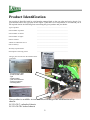
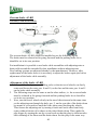
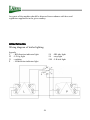
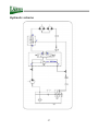
1
OPERATING INSTRUCTIONS
CHIPPER
LS 150-27 C
LS 150-27 CB
LS 150-38 C
LS 150-38 CB
Version 8.2013
Foreword
Thank you very much that you have just purchased our product, the chipper. Our
company has been engaged in production of equipment for wood residue crushing
and disposal for many years and has gained considerable experiences in this field.
Quality of our small and also powerful machines has been proven in 40 countries
worldwide we export to.
Permanent innovations of the Laski manufacturing assortment have been crowned
by the most important award in the company’s history, the golden medal Grand
Prix, gained for its complete family of chippers and shredders KDO and LS at the
international show:
Grand Prix Techagro
1998
Grand Prix Silva Regina 2002
Grand Prix Silva Regina 2008
This manual brings important instructions for users, i.e. instructions for putting the machine into
operation, work safety and operating experiences. You will learn how to carry out maintenance, repairs
and servicing and who is authorised for doing checks and other actions on the machine.
Your local dealer will give you this manual with instructions for operation and maintenance while taking
this new machine over. Make sure if you understand everything. If not, do not hesitate and contact your
dealer and ask him for explanation. It is very important for you and your work safety to understand all
instructions given in this manual.
The firm Laski, s.r.o. does not bear any responsibility for any claims resulting from disobedience to the
instructions given in this manual.
This operation manual includes also work safety instructions in various parts of the text. If there is any
work safety rule or instruction in general description, then this instruction is indicated with the following
symbol:
2
3
4
5
6
Contents
FOREWORD ........................................................................................................... 2
CONTENTS............................................................................................................. 5
PRODUCT IDENTIFICATION ........................................................................... 9
WORK SAFETY INSTRUCTIONS ................................................................... 10
UTILISATION ....................................................................................................... 10
NOT ALLOWED USE ............................................................................................ 10
GENERALLY ........................................................................................................ 10
WORK SAFETY SYMBOLS .................................................................................... 15
TRANSPORT OF PRODUCT/HANDLING ................................................................. 17
PRECAUTIONS IN DESIGN .................................................................................... 17
CONTROLS .......................................................................................................... 20
TRANSPORT SAFETY ON PUBLIC ROADS ............................................................... 22
Transport position .......................................................................................... 22
Trailer coupling/uncoupling........................................................................... 23
Putting aside and parking .............................................................................. 24
Trailer loading ............................................................................................... 25
TRAILER CHECKS BEFORE RIDE ......................................................................... 25
USE AND PRODUCT HANDLING ................................................................... 26
STORAGE............................................................................................................. 26
BEFORE PUTTING INTO OPERATION .................................................................... 27
TRAILER COUPLING ............................................................................................ 27
PUTTING INTO OPERATION .................................................................................. 28
CHIPPING ............................................................................................................ 29
PUTTING OUT OF OPERATION .............................................................................. 33
EMERGENCY SITUATIONS ................................................................................... 33
TECHNICAL DESCRIPTION ........................................................................... 33
Chipping Device ............................................................................................. 34
Loading chute ......................................................................................... 34
Chassis ........................................................................................................... 35
Technical Parameters..................................................................................... 35
OVERRUN BRAKE KNOTT .................................................................................... 37
ASSEMBLY AND DISASSEMBLY ................................................................................ 38
ADJUSTMENT OF THE BRAKE KNOTT...................................................................... 39
ASSEMBLY AND DISASSEMBLY ................................................................................ 40
7
ADJUSTMENT OF THE BRAKE AL-KO ..................................................................... 40
NOISE AND VIBRATIONS................................................................................ 42
MAINTENANCE ................................................................................................. 43
Lubrication ..................................................................................................... 43
Hydraulic Pump Belt Tightening .................................................................... 44
Blade Grinding ............................................................................................... 45
Adjustment of Chipping Device ...................................................................... 46
NOSTRESS System – Speed Regulation ......................................................... 46
TRAILER MAINTENANCE: ....................................................................................... 48
Overrun brake: ............................................................................................... 50
Hot-dip galvanized parts: ............................................................................... 51
Maintenance Intervals .................................................................................... 51
Checking, Oil Exchange ................................................................................. 51
FAILURES AND TROUBLESHOOTING .................................................................... 52
CHIPPER:............................................................................................................. 52
CHASSIS:.............................................................................................................. 53
WASTE DISPOSAL ............................................................................................... 55
ATTACHMENTS ................................................................................................... 56
WARRANTY ........................................................................................................ 58
SERVICE REPORT ............................................................................................ 59
8
Product Identification
Our product is identified with its serial number stamped both on the type plate and on its chassis. Pay
your attention also to the type plate on the engine. Upon take-over of the product we recommend you to
fill required data in the following form concerning the given product and your dealer.
Type of product:
…………………………………………………….
Serial number of product:
……………………………………………………..
Serial number of chassis:
……………………………………………………..
Serial number of engine:
……………………………………………………..
Dealer's address:
……………………………………………………..
Address of authorised service:
……………………………………………………..
Date of delivery:
……………………………………………………..
Warranty expiration date:
……………………………………………………..
Interruption of warranty period:
……………………………………………………..
The type plate is located on the machine frame.
It includes:
- manufacturer's data
- product trade name
- type
- serial number
- year of manufacture
- weight of machine
- CE designation
This product is available in two versions according to the modification of its
chassis:
LS 150-38/C: unbraked chassis
LS 150-38/CB: braked chassis
9
LS 150-27/C: unbraked chassis
LS 150-27/CB: braked chassis
Work Safety Instructions
Utilisation
For transport the chipper should be coupled to transport means equipped with a
towing bracket with a joint ball of size ISO 50 or with a hitch intended for a
drawbar/towing eye ∅40 mm.
This chipper is designed for disposal of wood waste, twigs, bark, branch-wood and
other above-ground biomass or for manufacture of chips from aforesaid materials
and also for disposal of redundant timber such as sticks, deals, pickets etc. The
chipper can dispose all these materials with diameter up to 150 mm or flat materials
with thickness up to 60 mm. The wooden pieces to be chipped must be free of
metal, glass and other similar objects.
The chipper should be controlled and operated by two operators who in turns load
materials to be chipped in a loading chute.
Not Allowed Use
The chipper is not allowed to be used for disposal of aforesaid materials with
foreign matters and objects such as metal, steel binding bands, glass cullet, stony
debris, ceramics etc.
It is not possible to use the chipper in the presence of unauthorised persons who
may stand or move in direction of discharge ducting. At work in residential zones
use the machine in accordance with regulations of the local authorities to avoid
disturbing of local inhabitants (noise level).
It is strictly forbidden to start the chipper with removed hoods and guards.
On hilly terrain its loading chute height should not exceed 600 mm.
Generally
-
-
This machine is allowed to be operated only by an operator who is over 18
yrs old, physically and mentally capable and demonstrably instructed with its
operation.
The chipper should be controlled and operated by two operators who in turns
load materials to be chipped in a loading chute.
Training courses for operating staff should include also practical operation
under supervision of an experienced person or your dealer and necessary
work safety instructions.
10
-
-
-
-
-
-
-
Before working learn all functions of individual controls and safety elements
and carry out functional checks
before any use. Check especially
loading of materials.
By pushing the concerned controller
in direction of material input the
machine should stop material
loading and by its next pushing the
loading rolls should turn back. The
controller frame has to be
advanced in front of the hinged
loading chute edge so that the
attendant stops the loading rolls or
let them turn back at pushing the
frame by leg or belly (positions C
and B)!
It is strictly forbidden to change or
to set the controller frame so that the STOP position (C) is under the loading
chute edge.
To stop loading you can push also the emergency STOP button under the
loading chute (E).
It is forbidden to retighten the nuts on the controller frame in order to
increase resistance to unwished stopping by loaded material. The control
force should remain in limits as set by the manufacturer, i.e. max. 80 N over
the total length length of the horizontal (upper) frame part.
It is strictly forbidden to remove guards and other safety elements. They serve
for your safety.
While chipping, it is not allowed to enter the area of ejected flying wooden
chips.
The end piece of the discharge duct can be set only in the angle (see fig.) to
longitudinal axis (upper turnable part) opposite to the loading chute. Do not
direct it toward the attendant's place!!
Keep this machine beyond
children's and unauthorised
person's reach. Avoid their
presence while chipping.
When using the chipper without
any container or closed bin,
11
-
-
-
-
keep anybody beyond the area where chips are thrown. .
When using the chipper with such a bin, never look inside if the chipper is
still working.
When leaving the machine take always the switch key out of ignition.
Every operator of this machine is fully responsible for any injury or damage
caused to the third persons within the operating reach of the machine.
At work in residential zones use the machine in accordance with regulations
of the local authorities to avoid disturbing of local inhabitants (noise, flying
chips).
Warning!!! Be aware of ejected particles. They have substantial kinetic
energy. If the loaded wooden material contains not allowed parts, such as
metal, sand, glass etc., then such objects can reach a longer distance than
wooden chips. Therefore direct the discharge duct in order to regulate
ejecting.
While coupling the chipper, do not stand between its towing bar and a
towing vehicle. Do not stand behind a towing vehicle while backing.
Before transport, fold always the discharge duct down. It must not remain in
its working position.
While putting the trailer aside, it should rest on its jockey wheel, be braked
by means of its parking brake (braked trailer) and blocked by means of
scotch blocks (unbraked trailer). Use always its supporting jockey wheel for
putting the trailer aside. While being uncoupled from a towing vehicle, its
travel wheels should be slightly unloaded by lowering of the front jockey
wheel and rear supports which makes this uncoupling easier.
Before transport, after coupling, lift up the jockey wheel under the drawbar
and both rear supports.
While chipping the operator is obliged:
to use only such a chipper which is in optimal operating condition, not
damaged through transport, storage or from previous operation,
to check functions of all controls and safety elements (especially functions of
the safety frame) before putting the chipper into operation,
to avoid disturbing of other people with noise, exhaust fumes or ejected flying
particles (at windy weather),
to keep traffic rules and local regulations when going or working on or nearby
public roads,
to turn the machine off if the discharge duct is clogged.
Clean the duct at standstill only. For cleaning use only suitable hooks or
bars to release pressed materials. After repeated putting the chipper into
operation let the machine run idle in the chipping mode to empty the whole
12
discharge ducting and the chipping wheel space. If proper cleaning is required
then take always the switch key out of ignition before removing hoods.
While working, never lean over the loading chute and never push wooden
materials with your hand or foot only. Use always a wooden stock or a bar to
push materials between the loading rolls
While working, wear always personal protective aids - protecting shield or
goggles, protective gloves, working shoes and working cloth properly
buttoned. Avoid wearing free parts, such as ties, scarves and shawls, belts etc.
In case of longer hairs use always a proper head piece. Otherwise, such a
person is not allowed to operate this machine.
In case of two attendants it is necessary to make simple signals clear before
working and to appoint one who will manage the work.
Both attendants must be trained in attendance and turning the chipper off in
emergency cases.
If any object, not allowed to be chipped, falls down into the loading chute, do
not try to pull it out with your hand. It is hazardous for your health and
operational safety. Turn always the machine off.
-
-
-
-
Keep traffic lights and work safety symbols in proper order.
Check up materials to be loaded and remove all undesirable objects. If you
see such particles in ejected chips stop working immediately.
This manual describes problems and faults which could occur at work and
which may be remedied by an instructed person. In case of other problems
and faults do not hesitate and contact the manufacturer. He is always ready
to help you.
Never do any technical changes or any actions which are neither given in this
manual nor allowed by the manufacturer. The machine, not correctly
installed or adjusted, may run without problems now but in the future it
could damage any of important parts. Pay regular attention to all joints and
bolts. Keep them properly tightened.
Do not put any objects or tools on the machine.
The manufacturer does not bear responsibility for any damages or injures to
the third persons or to other equipment resulted from disobedience to
instructions given in this manual.
When handing the machine over to another person make sure if all controls,
guards and other safety elements are complete.
Do not remove guards and other safety elements. They serve for your safety.
Keep the given intervals for checks of bolted joints.
13
-
-
-
Always after work clean all parts of the machine with pressure water. Pay
your attention especially to any oil spots or fuel leakage. Clean any oily
spots.
Some parts of the machine can be hot while in operation. Avoid any settling
of flammable chipped materials on such parts or close to the fuel tank, the
hydraulic oil tank and the exhaust manifold. Stop working if such deposits
exceed 1 mm.
Any servicing can be done only if the machine was put out of operation and
its chassis blocked against unwilling motion.
Do not use petrol as a cleaning agent.
Keep open fire away while filling the tank.
Keep the machine beyond reach of open fire.
Some parts of the machine run warm, such as hydraulic elements. Do not
touch them when the engine is still running or having been just stopped.
Do not let the engine running in high speed unreasonably.
Do not start the machine in confined or ill-ventilated spaces.
Do not carry out any repairs that are specified for authorised services only.
Do not carry out any repair where its solution exceeds your experiences.
It is strictly forbidden to work with damaged chipping device (out-of-balance,
vibrations while running).
While working on the chipping device, the chipping wheel should be blocked
against unwilling motion (e.g. by a locking pin).
Before transport on public roads
For transport on public roads the chipper LS 150-27 C (CB), LS150-38C (CB)
must comply with instructions in its operating manual and with applicable
legal regulations and permissible conditions for trailers, category O1.
For work close to public roads the towing vehicle must be equipped with a
beacon of orange colour for flashing..
Maximum transport/travel speed is 80 km.h-1.
For transport on public roads this chipper should be coupled to transport
means equipped with approved towing brackets. The given towing vehicle
should be approved for this way of transport and equipped with a respective
towing bracket intended for permissible weight of an unbraked trailer or, in
case of a braked trailer, for vertical coupling load of 50 kg at least and trailer
gross weight of 750 kg at least
Always before coming to a public road it is necessary to remove all mud and
accumulated sediments, especially from trailer tires.
14
Set the machine in the transport position, i.e. its loading chute backwards,
discharge duct turned, folded down and mechanically blocked against motion.
Couple the chipper to a towing vehicle properly and check up its proper
coupling.
Check up locks of the jockey wheel and supporting legs.
Plug and check up traffic lights on the trailer.
Keep the chassis in proper order for transport.
Respect all instructions for use by the manufacturer and applicable local
regulations.
Note: Be aware that traffic rules and regulations in different countries may differ.
Work Safety Symbols
15
1
Read this operating
manual before
use.
6
Warning! Ejected
objects hazard.
Keep away.
2
Always follow the
manual while
maintaining,
servicing or
repairing the
machine.
7
Warning! Close all
guards before
starting the
machine.
3
4
While
Warning! Hot parts.
coupling/uncou
pling the
trailer, do not
stand between
its towbar and
a towing
vehicle –
squeeze
hazard.
8
Wear personal
protective aids.
16
5
Warning! Turning
wheel is
running out.
9
10
Keep safety distance.
Warning! Risk of
high-pressure liquid
leakage.
11
12
13
14
Warning! Rotating
rolls. Pull-in
hazard.
Warning! Rotating
parts. Risk of
accidents.
Warning! Risk of
accidents.
Warning!
Inflammable matter!
Keep open fire
away!
The user is obliged to keep all the work safety symbols legible, clear and
undamaged. In case of any damage or illegibility ask your local dealer or
an authorised service for a new relevant pictograph.
This article introduces work safety symbols (pictographs) used on this machine.
Under the given pos. number there is their location on the machine. These work
safety symbols warn the operator against risks connected with the machine use.
Your respect to the symbol meaning is a precondition for your work safety.
Transport of Product/Handling
-
-
This product is delivered completely mounted and fitted on its own chassis.
While putting the chipper aside, block it against unwilling motion by means of
its parking brake system and scotch blocks. On flat surface it is sufficient to
block only one wheel from both sides.
Uncouple the chipper always on compact, flat and sufficiently bearing surface
only with inclination up to 10o.
Precautions in Design
This product is equipped with hoods, guards and covers protecting rotary and hot
parts against touching. Protective covers are usually fixed, bolted down on
framing.
17
An ignition box for starting with a
removable switch key. Confusion of
ignition keys is not possible. When
starting, first turn the key in the RUN
position. An orange signal lamp
indicates that the electric system on the
chipper is on. For proper functionality
of the loading rolls it is necessary to
turn the key in the START position and
finally release the key. A green signal
lamp is on which means the machine
safety circuit is activated. The engine
goes on running in the RUN position.
This ignition box does not allow
repeated starting if the key remains in
the RUN position but it must be turned
back in the initial OFF position and the
whole starting procedure must be
repeated
A safety frame for material loading
serves as an actuator for the loading rolls
control, i.e. stopping or reversing. Once
being pushed the chipper stops loading
motion immediately; the next pushing
18
Dangerous space behind the loading
rolls is protected with a hinged cover
and by a terminal switch which blocks
the driving engine before starting if the
cover remains opened. Once opened the
driving engine stops immediately. This
cover is locked with two bolts that
should be properly tightened.
behind the chute edge brings reverse .
turning of the loading rolls.
Dangerous space of the chipping wheel
and of the discharge duct is secured by
a terminal switch. To swing the
discharge duck away or to open the
upper half of the chipping wheel guard
it is necessary to unlock the guard and
to move it in the arrow direction, see
fig. It is not possible to put the machine
into operation if the guard remains
opened.
A safety pin of the chipping device
rotor serves for rotor blocking at blades
exchange and servicing. The pin is
chained on the edge of the machine
frame. A rubber plug protects the hole
for the pin. The chipping device is
blocked if the pin is inserted into a bush
on the rotor.
19
An emergency STOP button stops
dangerous motion of the loading rolls
and turns the engine off (like the safety
frame).
Controls
Ignition box
intended for control and feeding of safety
circuits.
NOTE:
To put the chipper into operation turn the key
in the position START (for starting) and then
let it in the position RUN.“
20
Safety frame for material loading
MATERIAL LOADING - pulling forwards
- STOP - central position
- REVERSE - back position
Control lever on safety frame for loading,
stopping and reversing; emergency STOP
button on upper chute part
Lever for V-belt tightening intended for
chipping wheel drive
Controller of in-feed speed
Loading rolls speed regulation in range from 0 to 40
m/min
21
Emergency STOP button - stops dangerous
motion of the loading rolls and turns the
engine off.
Transport safety on public roads
For transport on public roads this chipper should be coupled to transport means
equipped with approved towing brackets. The given towing vehicle should be
approved for this way of transport and equipped with a respective towing bracket
intended for permissible weight of an unbraked trailer or, in case of a braked
trailer, for vertical coupling load of 50 kg at least and trailer gross weight of 750 kg
at least. If the towing vehicle is equipped with a 13-pin receptacle for transport
lighting, it is possible to use an applicable adapter for a 7-pin plug. The trailer can
be also equipped with a 13-pin plug (option).
•
•
•
For transport on public roads the trailer must comply with instructions in its
operating manual.
Maximum transport/travel speed is 80 km.h-1.
Always before coming to a public road it is necessary to remove all mud and
accumulated sediments, especially from trailer tires.
Transport position
First make the machine ready for transport:
turn the engine off;
empty the rear loading chute;
couple the trailer on the towing bracket ball, or
insert the drawbar in the hitch and lock it with a locking pin;
connect the brake safety rope to the towing vehicle;
release the parking brake;
22
lift up the jockey wheel under the drawbar;
retract the supporting foot in rear and lock it mechanically;
turn the discharge duct to the left, fold it down and lock it mechanically;
fold down the end piece and lock it mechanically;
connect the electric plug to the towing vehicle.
Trailer coupling/uncoupling
For transport this chipper can be coupled to transport means equipped with a
respective towing coupler B50-X (with a ball ISO, ∅ 50 mm) or through a drawbar
eye ∅ 40 mm in the towing vehicle hitch. The given vehicle should be approved
for transport on public roads.
•
While parking the unbraked trailer, block it against unwilling motion with
scotch blocks. Should the trailer be braked, retract its parking brake. On hilly
terrain, in addition to that, block it against unwilling motion with scotch
blocks.
•
While coupling, go always with the towing vehicle to the trailer. Be careful,
this approaching could be dangerous, particularly on hilly terrain.
•
First of all, set the drawbar in required height by means of its jockey wheel.
•
Coupling through a ball coupler:
•
Hold the coupler on its grip and put it on the ball in rear of the towing vehicle.
After snapping on the ball release the grip and the coupler gets automatically
locked. The pointer on the ball coupler Knott must be within the „+“ range. In
case of the AL-KO ball coupler you should see the pointer in a green field.
•
Try to lift it up by hand to check out if the ball coupler is properly locked.
• Coupling through a drawbar eye, ∅ 40 mm: :
• Having approached the towing vehicle to the drawbar and after its height
adjustment by means of the jockey wheel put the eye into the hitch.
Automatic couplers lock the drawbar inside by a pin automatically.
• In case of manual couplers put the eye into the hitch and insert its locking
pin. After snapping lock the pin by its locking spring or dowel against
unwilling uncoupling.
• Check out proper coupling and locking of the trailer drawbar.
•
For a braked variant: connect the brake safety rope to the buffer, frame or
towing bracket in rear of the towing vehicle. This rope of the overrun brake system
should be led directly to the towing vehicle and freely for all reciprocal movements
both of the trailer and the vehicle.
23
•
If the towing vehicle is equipped with a 13-pin receptacle for transport
lighting, it is possible to use an applicable adapter for a 7-pin plug. The
trailer can be also equipped with a 13-pin plug (option).
While uncoupling the trailer, proceed in reverse order. Do not uncouple the trailer
on a hillside as it is very dangerous. Before uncoupling, make sure if the trailer is
sufficiently blocked against unwilling motion after uncoupling from the vehicle.
Putting aside and parking
Unbraked trailer
Do not park the trailer on hilly terrain. It is very dangerous as the trailer is not
braked. While parking, block it against unwilling motion with scotch blocks under
both wheels.
While putting aside or parking the trailer being coupled to the towing vehicle,
retract the parking brake on the vehicle and, on hilly terrain, block it against
unwilling motion with scotch blocks under both trailer wheels and at least under
one wheel of the towing vehicle.
Braked trailer
While braking the braked trailer, retract its parking brake by means of a control
lever (in the position BRAKED). While putting aside or parking the trailer being
coupled to the towing vehicle, retract the parking brake on the vehicle and also on
the trailer. On hilly terrain, in addition to that, block it against unwilling motion
with scotch blocks under both trailer wheels and at least under one wheel of the
towing vehicle.
.
CAUTION! Before removal of scotch blocks, first find out if the parking
brakes can hold the whole set or the trailer also after this removal.
.
For a longer putting the trailer aside, for example in winter time, block the trailer
against unwilling motion so that its wheels are underlaid or supported without load
and its parking brake remains released. In this way you can save tires, bearings and
springs.
.
24
Trailer loading
While loading on a transport vehicle, the trailer must be properly fixed on the
loading surface, lashed and secured against any displacement or overturning.
This trailer is not designed for handling by crane, i.e. it has no lashing points.
While loading on a transport vehicle, no persons are allowed to be under the
trailer or in its close vicinity – risk of accidents.
.
Trailer checks before ride
The driver is obliged to carry out the following checks, in particular:
•
wheels fixing
•
condition of tires, tire pressure
•
condition and function of lights and reflector glasses
•
trailer coupling, condition of towing bracket/hitch, drawbar eye and its
locking
•
condition of overrun brake system and parking brake (braked variant)
•
connection of brake safety rope (braked variant)
•
fixing of machine parts on chassis (in their transport position)
•
if there are no loose parts or tools laid on the trailer
•
if the trailer is set in its transport position, i.e. engine off and concerned
parts fixed
•
if the jockey wheel is sufficiently lifted up and locked mechanically;
•
if the supporting foot in rear is retracted and locked mechanically;
•
if the parking brake is released (braked variant)
•
if the trailer is free from mud and dirt
25
Chipper ready for transport
Discharge duct folded down
Use and Product Handling
Storage
Store the chipper always in a dry shelter to protect it against weather effects.
• Keep the stored machine beyond unauthorised persons reach.
• Before storage clean all parts of the machine. For cleaning you can use
pressure water. After cleaning let the machine get air-dried. If some water
penetrated into the chipping device space, let also this space get dried.
• Clean especially oily spots.
• Exchange all damaged or worn parts. Use always original spare parts. For
spare parts contact your dealer or authorised services.
• Do not apply any grease or similar agents on elastic hydraulic hoses.
• Always put the machine aside on a flat and solid floor and block its wheels
against unwilling motion by means of scotch blocks. We also recommend
putting it aside on a wooden pallet.
• Do not put any objects or tools on the machine.
26
Before Putting into Operation
-
-
Before the first putting into operation check up the machine for contingent
damages and completeness after its transport and storage.
Check out tightening of bolted joints, especially guards, grids and
completeness of other parts.
Check out movability of turnable parts (loading chute, discharge duct etc.).
Check out work safety labels for completeness and legibility. Replace any
damaged and illegible label, if necessary.
Grease bearings and sliding parts.
Check out the engine oil level with a dipstick and refill if necessary. The oil
level must be between both marks (MIN and MAX).
Plug the traffic lights and check their function.
Do not try to repair the machine if it is beyond your competence. Any
servicing, especially of rotating parts, should be carried out by authorised
persons only.
Check out condition of blades. Replace them if worn or damaged.
For replacement use always original spare parts. Parts, such as rotors, should
be balanced properly.
All blades should be replaced always at the same time as a set. Pay special
attention to their fixing bolts. Replace them if worn or damaged.
Avoid spillage at filling oil or fuel. Use always a proper filling funnel. If any
fuel or oil is spilled or overflowed then wipe off the spots immediately.
Do not use petrol or similar inflammable matters as a cleaning agent.
It is strictly forbidden to do any technical changes on the machine.
If any readjustment is required, do it always at standstill only. Remember
blocking the wheels against unwilling motion.
Check out condition and proper tightening of V-belts.
It is strictly forbidden to start the chipper with removed hoods and guards.
Start the machine always without its chipping device being engaged (with
loosened V-belts). Do not start the machine in confined or ill-ventilated
spaces.
Trailer Coupling
Coupling
While coupling the chipper, do not stand between its towbar and a
towing vehicle. Do not stand behind a towing vehicle while backing.
Ask other person to assist you at coupling.
27
Plug and check traffic lights of the chipper. If the towing vehicle is equipped
with a 13-pin receptacle for transport lighting, it is possible to use an
applicable adapter for a 7-pin plug. The trailer can be also equipped with a
13-pin plug (option). Connect the brake safety rope to the buffer, frame or
towing bracket in rear of the towing vehicle.
Putting into Operation
Before start check up if the loading chute is free of any materials. Direct
the discharge duct out of possible motion of other persons or prevent
other persons to enter the working area. At work proceed always very
carefully
Swing away the hinged part of the loading chute and lock it.
Avoid directing the discharge duct to the area of possible motion of other
persons.
Set the guard under the discharge duct in its top position and lock it by a nut.
Set the safety lever in the central STOP position to block the loading rolls.
28
Sink supporting legs and the jockey wheel until the travel wheels are
unloaded/lifted up slightly.
Close all guards (if opened).
Set the control lever in the position LOADING.
Set the switch key in the START position. Having the engine started, release
the key in the position RUN. CAUTION!! The loading rolls start turning.
Carry out functional checks of the safety frame on the loading chute. Set the
lever in the in-feed position and the loading rolls start turning (loading). By
first pushing the frame the rolls should stop loading immediately
(EMERGENCY STOP), the next pushing behind the chute edge (D) brings
their reverse turning.
Legend:
A - loading chute, B - safety frame, C - attendant's place, D - loading chute edge,
E – in-feed direction, G - control lever
•
The safety frame must be always adjusted so that the
EMERGENCY STOP must be activated before the point D –
loading chute edge.
Do not leave the machine unattended.
Chipping
This chipper is driven by a combustion engine. Do not start it in confined
or ill-ventilated spaces or under conditions of low visibility.
•
29
•
•
-
-
While chipping, the chipper chassis (the trailer) must be properly blocked.
You may let the chipper coupled to a towing vehicle. Just turn the loading
chute and the discharge duct in the required direction.
The end piece of the discharge duct should be set only in the angle, see fig. Do
not direct it toward the attendant's place
While working, the attendant should stand only on the given attendant's place.
Having turned the chipping wheel on, wait for stabilisation of its speed. Then
you may increase or reduce this speed by means of the engine speed regulator.
Wooden chips can be gathered in bulk or into a container located on a towing
vehicle.
When discharging into a container pay your attention to ejecting in order to
avoid ejecting chips out of the container.
Before displacement of the chipper to another workplace, first turn the engine
off and wait for run-out of all rotary parts.
Do not load materials with parts of metal, glass and other similar objects.
Do not chip or load materials while driving.
Having put materials in the loading chute/between the loading rolls, release
loaded materials immediately and keep a certain distance from the chute.
While working, never lean over the loading chute and never pull out wooden
materials, already loaded, from the chute.
Do not load materials with diameters exceeding 150 mm.
If loaded materials are spreading with risks of catch holding of attendant's
dress being drawn in the loading chute then it is necessary to prepare such
materials accordingly.
Pay special attention to thorny materials, such as acacia and roses, which may
easily catch your sleeves.
30
-
-
Be careful while loading since materials may unexpectedly move in unwished
directions.
In case of two attendants it is necessary to make simple signals clear before
working. During operation it is not easy to make any agreements because of
operating noise.
Observe the working area. If any person, children or animals approach while
chipping, then stop working immediately.
Be aware that there is a certain time period between loading and ejecting of
the last chips.
As far as possible load the chipper evenly, adapt loading speed accordingly
and keep continuous chipping.
While loading, stand aside the loading chute.
When loading short materials throw them in the chute and push them forward
between the loading rolls by means of a wooden rod or another branch.
Never use metal objects. They could cause serious damage of the loading rolls
and chipping blades.
When finishing the work first wait for emptying of the loading chute.
Should some bar material be loaded, then particular bars should be up to 3 m
long.
Recommendations:
Do chipping always at max. engine speed, i.e. at sufficient
power of the chipping wheel for ejecting of chips.
While being loaded, short and fine materials may deposit
or clog the space behind the loading rolls in front of the
chipping wheel. To avoid such problems and clogging put
occasionally also some longer branches.
To prolong service life of blades never put any materials
with foreign matters, such as metal, glass, ceramics and
other similar objects.
Optimal sharp blades reduce operating costs of the
loading and chipping equipment (reduced wear of the
chipping device).
If loaded material is free of any foreign matters then a
grinding interval for blades may last several months or
several hundred m3 of loaded materials.
31
Blunt blades are evident on chipped edges that are not
clean but broken.
Should the chipper be used for chips shredding, then it
brings higher energy intensiveness.
Short and fine materials, leafed and coniferous branches
with low wood mass may deposit or clog the space behind
the loading rolls in front of the chipping wheel.
The chipper is equipped with the NOSTRESS equipment monitoring speed of its
chipping wheel and control of continuous material feeding in accordance with
actual engine load which provides continuous run and reliability in service.
The chipping wheel speed is set by the manufacturer to 1588 rpm to turn the rolls
off and to 1590 rpm to turn the rolls on again.
Recommendations:
Should the loading rolls be frequently turned off while chipping,
it means that there is too much material loaded and the chipping
device is overloaded. To avoid this overloading:
- reduce volume of material to be loaded, or
- reduce in-feed speed of the loading rolls
The loading rolls in-feed speed can be reduced by the regulating screw (see arrow)
above the loading chute.
To change the in-feed speed, just turn the regulating screw accordingly.
32
Putting out of Operation
If you want to stop chipping:
- In case of loaded material wait for emptying of the loading chute.
- Wait for emptying of the discharge duct.
- Turn the chipper off.
- Turn the switch key in the STOP position without regard to run-out of the
chipping wheel.
Emergency Situations
Put the chipper out of operation immediately in following cases:
- If any person or animal approaches under 20 m while chipping, then stop
working immediately.
- If any breakage, damage or disengagement occurs, stop chipping immediately.
- If you heard any strange noise or vibrations or felt a strange smell while
chipping, then turn off the machine immediately and contact your dealer or
directly the manufacturer.
- In case of fire or breakdown, stop chipping immediately.
- In case of fire use foam extinguishers only.
- If you cannot damp the fire down yourself, call for a fire brigade.
- If an attending person gets caught by rotating parts or loaded materials stop the
loading rolls by pushing the safety frame. Stop working and go on only if the
attending person is uninjured and fully concentrated.
- If the discharge duct gets clogged, stop loading immediately and reverse the
loading rolls by pushing the safety frame (position REVERZ). Turn the
chipper off and having all rotary parts stopped (after about 1-2 min) use an
elastic rod and try to release the clogged material in the end piece of the
discharge duct. Having released clogging materials, try to turn on the chipper
again. If not, hinge away the upper hood part and try to remove all materials
by hand (the chipper must be OFF). Be aware, the chipping wheel must be
blocked properly.
Technical Description
This machine consists of the following main parts:
- chipping device
33
loading chute
loading rolls
chipping wheel
discharge duct
-
chassis
Chipping Device
Loading chute
The hinged part serves as an extension of the chute with a safety frame. This frame,
if pushed by an attending person or branchy materials being caught, turns the
loading rolls off. The chute itself, shaped as a square pyramid, is decreased in width
toward the loading rolls and in this way loaded materials are pressed together.
Loading rolls
They take over loaded materials and move them to the chipping wheel. Their speed
can be regulated according to the given sort of material and expected results –
chips. Its top rolls are transversally ribbed.
The top roll is height-adjustable according to the given material. Both rolls are
driven by a hydraulic motor
Chipping wheel
It is a steel disc serving also as a flywheel for absorption of shocks while chipping.
The wheel is bedded in ball bearings; a drive pulley is fitted on its shaft. The wheel
is equipped with two blades for cutting of loaded materials. The vanes welded on
its rear side serve for ejecting chips in the discharge duct. Optionally it is possible
to complete the machine also with shredding hammers behind the chipping wheel
intended for breaking of wood mass.
The chipping wheel is installed in a rigid frame and protected by a steel plate. Its
protective shield consists of two parts and particular parts are bolted together. By
safety reasons the upper hinged part is protected with a terminal switch for turning
the drive off if the shield remains opened or got loose.
Discharge duct
This duct continuously prolongs the chipping wheel shielding and serves for
directing chips being ejected. The duct is turnable and its end piece (“tilting gate”)
serves also for setting the range of ejected chips.
34
Chassis
The chipper LS 150/27, LS 150/38 is fitted on a special single-axle trailer, cat. O1.
Its variant A is unbraked; its variant B is provided with an overrun brake. For
coupling to a towing vehicle the trailer is equipped with a fixed drawbar and a ball
coupler B50-X or a towing eye ∅40 mm.
The chipper is powered by an independent combustion engine. The chipping work
is allowed to be done only with the trailer standing.
Necessary coupling device, overrun brake system, axle and brakes are subgroups
delivered by f. AL-KO or Knott.
The rear bumper beam complies with applicable EU standards, particularly the
Directive No. 70/221/EHS.
Its travel wheels, protected with plastic mudguards, comply with applicable EU
standards, particularly the Directive No. 91/226/EHS.
Its engine, fuel tank and hydraulic oil tank are installed in the front part of the
frame, protected against accidental damage by the chipper itself and by a rear
bumper beam.
On the trailer mudguards there are white reflector glasses installed; in rear of the
trailer there are two combined lamps with side, stop and direction indicator lights,
sign plate light, rear triangular red reflector glasses and a fog lamp on the left side.
Aside on the mudguards there are orange reflector glasses. All the lamps and
glasses are approved for transport on public roads complying with applicable
standards (EHK No. 48).
Standardly the trailer is equipped with a 7-pin plug. Should the towing vehicle be
equipped with a 13-pin receptacle for transport lighting, it is possible to use an
applicable adapter for a 7-pin plug. The trailer can be also equipped with a 13-pin
plug (option).
For putting aside the trailer is equipped with an adjustable jockey wheel under the
drawbar. Two scotch blocks are put in holders on the front frame part.
Tire pressure, see the plate on the mudguards.
This trailer is not equipped with a spare wheel.
Technical Parameters
Parameter
Unit
Value
LS 150-38
C
Chassis type
Type
Variant
-
Version
Trade mark
-
LS 150-38
CB
LS 150-27
C
LS 150-27
CB
Special trailer with chipper, cat. O1
S1
A
B
A
B
(unbraked) (braked) (unbraked) (braked)
150/38
150/27
LS 150/38 C (unbraked)
LS 150/27 C
(unbraked)
35
LS 150/38 CB (braked
Overall length / for transport
Overall width / for transport
Overall height / for transport
Overall height / in working position
Wheel base
Weight (operating)
Weight (max. permissible)
Axle load (max. permissible)
Overall length / for transport
Overall width / for transport
Overall height / for transport
Tires
mm
mm
mm
mm
mm
kg
kg
kg
kg
kg
-
3278
LS 150/27 CB
(braked
3278
3470
3470
1590
1690
2380
1793
-
Tire pressure
Wheel rim
Max. travel speed
Electric installation
NOSTRESS supply voltage
Chipping device:
Chipping wheel – diameter
- number of blades
- number of shredding hammers
- rate of cutting
Max. diameter of materials to be
disposed
Chipping wheel drive
Loading device:
Inlet hole size
kPa
km.h-1
V
1995
1793
1995
750
750
750
50
600
Class B50-X (ball ISO ∅50 mm)
Class S (towing eye ∅40 mm)
155/80 R13 84 N
155 R13 84 N
270
4½ J x 13 H2
80
12 V, 7-pin plug
12
mm
m.s-1
mm
560
2
2
42
150
-
3 belts B17x 1250 Li
mm
290 x 220
Number of loading rolls
Diameter of rolls
In-feed speed
Drive
Turning-off speed
Turning-on speed
Speed regulation
Loading chute:
Feeding profile
Engine:
Type
mm
m.min-1
min-1
min-1
-
2
190
12 - 40
hydrostatic
1588
1590
NOSTRESS
mm
910 x 810
Power output/revolutions
Oil charge
kW
l
36
KOHLER COMMAND
CH 980 S
KOHLER COMMAND
CH 740 S
28,3 at 3600 rpm
2,91
20,1 at 3600 rpm
1,9
Oil sort
Lubrication
Fuel
Fuel tank capacity
Max. engine inclination
Alternator
Starter
Battery (lead-acid)
l
o
V/Ah
Trailer braking system
Overrun brake Knott
37
15W-40
forced with full-flow oil filter
Petrol, ON 95
16
25 in all directions
12 V, 20 A
electric
12/44
Assembly and disassembly
The overrun brake Knott should be installed as per the following figure. It is very
important that the drawbar with its ball coupler or with its towing eye should be
fully protruded forwards and the parking brake lever should be set in its zero
position. Screw the threaded brake bar about 15 mm in the fork nut and lock it by
the nut “F”. Screw freely other nuts as per the figure.
On the rocker arm it is possible to use a ball nut M8 instead of the ball washer “H”
and the nut M8 “D” and on the bars a ball nut M10 instead of the ball washer “H”
and the nut M10 “C”.
CAUTION! The parking brake lever remains under prestress. Do not
remove the red locking thumb screw M10 until all the control elements,
brake bars and the entire braking system are fully installed and adjusted.
38
Before disassembly of the control device or the braking system elements as well as
before any routine maintenance or repair it is necessary to have this safety screw
unconditionally screwed in. Any disobedience to this rule may bring accident risk
since the parking brake lever could release its prestressed spring.
.
Adjustment of the brake Knott
1. Lift up the trailer by means of lifting jacks so that its travel wheels can
freely rotate and loosen the nuts “C”, “D” and “G”.
2. The following steps are the same as on the other trailers, i.e. the drawbar is
fully protruded forwards, the parking brake lever is in its zero position and
the threaded brake bar is locked by the nut “F” in the fork nut.
3. Finally, turn the travel wheels slowly in the travel direction and at the
same time set the check screw “B” until the brake shoes start blocking the
wheels. Then loosen the check screw by turning it by ½ to ¾ turn back so
that each wheel can freely rotate without friction of its shoes on the wheelbrake drum.
4. Having adjusted the drum brakes, screw the nuts “C” and “D” to the
rocker arms “E” and lock them by counter nuts. The nut “D” should be
screwed on the bar about 8-10 mm. The main brake bar must be locked
without any prestress but with max. play of 1-2 mm.
5. Screw the nut “G” to the spring suspension “A” without any prestress and
lock it.
6. Having finished, apply the hand brake lever and release it repeatedly 3 or 4
times.
7. If some play occurs, remove it by setting the nuts “C” and “D”.
8. When the brake system is properly adjusted, then the brake effect must be
evident after about 10-15 mm behind the dead point.
9. Should the brake system be adjusted with too small play, then you need
more power for backing.
10. To check out functionality of the brake system we recommend a test run
with two or three braking actions. If some play occurs, see the abovementioned steps.
11. If some faults in adjustment persist, contact your dealer or authorised
service.
It is necessary to proceed in the given order, i.e. first to adjust the wheel brakes and
the rocker arm must be upright on the main brake bar.
The red safety screw should be removed first after adjustment of the whole braking
system.
39
Overrun brake AL-KO
Assembly and disassembly
The overrun brake AL-KO should be installed as per the following figure.
The brake must be released as for going forwards and the parking brake lever
should be set in its zero position.
For installation it is possible to use brake cable assemblies with adjusting nuts or
brake cable assemblies intended for fast installation without adjusting nuts.
New braking systems are adjusted already by the manufacturer. However, after
replacement of the brake shoes it is necessary to adjust the brakes again just before
adjustment of the brake cable assembly.
Adjustment of the brake AL-KO
1.
2.
3.
Lift up the trailer by means of lifting jacks so that its travel wheels can freely
rotate and loosen the nuts, pos. 8 and 10, on the bar and the nuts, pos. 4 and 5
on the brake cable assembly.
The following steps are the same as on the other trailers, i.e. the overrun brake
must be released as for going forwards and the parking brake lever should be
set in its zero position.
Now, turn the travel wheels slowly in the travel direction and at the same time
set the adjusting nut through the hole, pos. 2, on the rear side of the brake drum
by means of a screwdriver until the brake shoes start blocking the wheels.
Then loosen the adjusting nut by turning it back until each wheel can freely
rotate without friction of its shoes on the wheel-brake drum. Then, make the
play bigger by turning the nut by several teeth so that the play is sufficient also
after warming of the shoes and the brake drum. Set the play in the same way
40
also on the opposite wheel. New brakes do not need any adjustment since they
are adjusted by the manufacturer.
4. Set the play by a ball nut, pos. 10, for the control mechanism.
5. Set the brake cable assembly length by the nuts, pos. 4, so that the rocker arm,
pos. 6, is upright to the main bar, pos. 3. If the system is equipped with brake
cable assemblies intended for fast installation without adjusting nuts, then go
directly to the step 6.
6. Set the play of the control mechanism by means of the nut, pos. 10, so that the
rope, being drawn on the rocker arm, can be pulled out approximately by 4
mm. It corresponds with the proper play inside the brake, required for
avoidance of slight braking and warming while driving. Finally lock the nut,
pos. 10, by means of the counter nut, pos. 8.
7. Having finished, apply the hand brake lever and release it repeatedly 3 or 4
times.
8. If some play occurs, remove it by setting the nut, pos. 10. If the rocker arm did
not remain in its upright position, readjust the brake cable assemblies again by
means of the nut, pos. 4. In case of brake cable assemblies without adjusting
nuts readjust the play setting in the brakes.
9. When the brake system is properly adjusted, then the brake effect must be
evident just behind the dead point.
10. Should the brake system be adjusted with too small play, then you need more
power for backing.
11. To check out functionality of the brake system we recommend a test run with
two or three braking actions. If some play occurs, see the above-mentioned
steps.
12. If some faults in adjustment persist, contact your dealer or authorised service.
It is necessary to proceed in the given order, i.e. first to adjust the wheel brakes and
the rocker arm must be upright on the main brake bar.
Instructions for operation
1. Having pulled the parking brake on hilly terrain and due to backing
automatics the vehicle can move back approximately by 25 cm until the
brake effect occurs. So, when using the parking brake, be aware of from
other vehicles or obstacles behind the trailer.
2. The brake safety rope is connected with the parking brake lever. At
unexpecit and keep a safety distance
41
3. ted uncoupling of the trailer from the towing vehicle the safety brake rope
activates the parking brake that should brake the trailer. Therefore the
safety brake rope must be properly connected to towing vehicle and led
directly (freely) without risk of its catching or tangling on the trailer parts.
If the towing vehicle is not equipped with a corresponding eye, make a
loop on the towing bracket ball.
4. Lift fully up the jockey wheel under the drawbar and lock it in its top
position to avoid its getting loose and falling down. If its top position is
not sufficient, loosen its holder and lift it more up.
Travel wheel replacement
Any drive with a damaged tire or wheel rim is very dangerous; the tire can blow
out and cause a road accident. Should any fault or damaged be detected on the tire
or on the rim then do not hesitate to replace a complete wheel. However, this trailer
is not equipped with any spare wheel.
• In case of light untightness it is possible to repair the tire by means of a special
spray intended for tire service.
• Before wheel replacement block the trailer against unwilling motion by means
of its parking brake or scotch blocks.
• The lifting jack should always stand under the place of axle fixing. Otherwise,
it could damage the axle.
• All the wheel nuts should be tightened by torque 90 Nm.
• Inflate the tire to pressure of 270 kPa.
• After the first 50 km check out proper tightness of the wheel nuts.
Noise and Vibrations
Operation of this chipper brings following emissions:
Measure
LS 150 – 38
unit
C
Noise LAeq
dB
Sound power - measured
dB
LWA - guaranteed
All measurements taken in accordance with:
Values
LS 150 – 38
CB
LS 150 – 27
C
90,0
91,0
104,2
104,2
105,0
105,0
EN ISO 11201, EN ISO 3744
Extended uncertainty of measurements: U = t 0,6 dB
While working, the person operating this machine is obliged to use personal
protective equipment efficient against the given noise accordingly.
42
LS 150 – 27
CB
Maintenance
•
•
•
•
•
•
•
Any servicing of the chipper should be carried out by authorised
persons only.
• Check up the machine for completeness and its general condition.
Before any servicing, first turn off the chipper and block the trailer against
unwilling motion.
Pay special attention to safety elements.
Check up V-belts for tightness and wear.
Keep regular intervals for lubrication of bearings.
Check up condition of blades, shredding hammers and chipping wheel vanes
regularly.
Check up hydraulic hoses for wear. Replace them if necessary or every five
years
Lubrication
Grease cup of chipping wheel
Lubrication every 40 running hrs
(weekly)
Grease cup of chipping wheel
(under hood); lubrication every 40
running hrs (weekly)
43
Grease cups on towbar
Lubrication every 10000-12000 km or
once a year
Grease cups of loading rolls
Lubrication every 40 running hrs
(weekly)
Grease cup of tension pulley
Lubrication every 40 running hrs
(weekly)
Hydraulic Pump Belt Tightening
The hydraulic pump is powered by the
PTO shaft. The pump is accessible after
removal of its guard. To tighten the Vbelt, loosen the fixing bolts and just
move the whole pump assembly on its
guides. After tightening, retighten the
fixing bolts.
44
Blade Grinding
Blades, fitted in the chipping wheel, are double-sided, i.e. reversible if one side is
blunt.
Blades edge regrinding requires high demands for keeping cutting edge shape.
While grinding it is necessary to keep its optimal geometry, see the following
figure. A right shape prolongs blade service life.
While regrinding it is necessary to keep the same weight of particular
blades because of balance of their rotating mass. For grinding use
always a grinder with a magnetic table and a special fixture.
Detailed geometry of blade edge
Grind the blade only up to minimum distance from the edge to its fixing
bolt axis which is 37,5 mm. This distance on a new blade is 100 mm, see
the following figure.
45
Max. wear/grinding of cutting edge
Adjustment of Chipping Device
Optimal operation of the chipping device requires right setting of the clearance
between the blade and the opposite cutting edge. This distance should be set (see
the following figure) and checked after fitting the ground blades, then it grows with
their wear and chipped branches may be squeezed between the blade and the
opposite edge. It brings deterioration in quality of chipping.
Pay attention also to the blades exchange. In such case set the given clearance
bigger to avoid damage of a new blade and its opposite cutting edge.
.
Recommendation: Check out conditions of blades every 40 operating
hours. Regrind blade edges if they are found blunt.
Jointing elements (bolts and nuts) should be replaced together with
the blades exchange. Safety nuts should be used only once, since
they lose their self-locking properties if used repeatedly
NOSTRESS System – Speed Regulation
(Option)
This system is intended for overload protection of
the combustion engine consisting of an electronic
control unit and a speed sensor installed on the rotor
shaft.
46
NOSTRESS ON – the chipper works with automatic regulation of loading (no
engine overloading).
NOSTRESS OFF – the chipper works without automatic regulation of loading.
This way of operation is recommended only in case of a failure of the control unit.
• Control unit:
This control unit displays actual rotor speed values. When the rotor stops, the unit
displays a total number of running hours "th". To display a daily number of
running hours, just press the button "S". To reset this daily number, just press the
button "S" once to display a total number of running hours "th" and then press it
again and hold for total resetting. This control unit is protected by two fuses: 7,5 A
– installed just by the unit and 4 A – installed inside.
• Right function of NOSTRESS system:
The speed regulator reduces material feeding upon contingent overloading. The
chipping wheel speed is set by the manufacturer to 1588 rpm to turn the loading
rolls off and to 1590 rpm to turn the rolls on again. Actual rotor speed values are
displayed on the control unit.
• Speed sensor:
This encapsulated sensor in fitted on a holder keeping its distance of 2 mm from
the cam lobe. In the rear part of the sensor sleeve there is an orange LED installed
flashing in case of proper sensing.
47
Set-up of the speed sensor distance should be done at
machine standstill only
Location of sensor under hood
Trailer maintenance:
Check up the trailer daily for good technical condition (before ride) and remove
detected faults. The trailer should be ready for operation only in good technical
order.
Keep all the routine maintenance intervals. Should the trailer (chipper) work in
dusty and heavy conditions, shorten these intervals accordingly.
Checks on unbraked trailer:
1.
After first 500 km:
- all bolted joints and retighten if necessary
2.
Every 5 000 km or every 12 months:
- all bolted joints and retighten if necessary
- axle, springs, parts for excessive wear or contingent damages and
replace them if necessary
- wheel bearings are maintenance-free (with permanent grease packing)
- exchange them only in case of contingent damage
- ball coupler and towing bracket or towing eye and hitch: apply
corresponding grease film on their surface (e.g. as per DIN 51825 KTA
3K4)
- coupling parts for excessive wear or contingent damages and replace
them if necessary
48
- tires and wheel rims for wear or contingent damage
- jockey wheel and its mechanism
- lights and reflector glasses
- plug and cables of electric installation - exchange them only in case of
contingent damage
Checks on braked trailer:
1. After first 500 km:
- all bolted joints and retighten if necessary
2. After first 5 000 km or 6 months:
- brake clearance between linings and brake drum
3. Every 5 000 km or every 12 months:
- all bolted joints and retighten if necessary
- axle, springs, parts for excessive wear or contingent damages and
replace them if necessary
- wheel bearings are maintenance-free (with permanent grease packing) –
exchange them only in case of contingent damage
- brake lining thickness (through inspection holes in rear brake drum
shields)
- ball coupler and towing bracket or towing eye and hitch – apply
corresponding grease film on their surface (e.g. as per DIN 51825 KTA
3K4)
- coupling parts for excessive wear or contingent damages and replace
them if necessary
- functionality of overrun brake incl. backing automatics and parking brake
- readjust them if necessary
- lubrication of overrun and parking brake mechanism – use always lithium
grease (such as Castrol LM Grease, Castrol Spheerol AP2 or Fuch Renolit
GL2)
- sensitiveness and response of overrun mechanism: set the hand brake
backwards as much as possible and push the ball coupler with the towbar
in the overrun brake – this pushing must be connected with increasing
force. After release the towbar must go slowly forwards in its initial
position (it must not “shot out”). If it is not possible to push the towbar
check it for dirt or sediments and apply some grease. If this fault persists,
the overrun mechanism must be repaired or replaced in authorised service
(AL-KO or Knott).
- tires and wheel rims for wear or contingent damage
- jockey wheel and its mechanism
- lights and reflector glasses
49
- plug and cables of electric installation - exchange them only in case of
contingent damage
4. Every 10 000 km or every 24 months:
- removal of brake drums and inspection of brake shoes, lining and drum
for wear and contingent cracks or damage; in case of drum exchange
replace also brake shoes
- inspection of brake shoes and backing automat springs
- functionality and condition of shoe brake mechanism with pins – replace
them if necessary
- functionality of backing automatics – apply some grease
- brake clearance between linings and brake drum – readjust if necessary
- apply grease on braking bowden cables
- tightening of wheel nuts – torque for Knott axles: 280 Nm
2)
3)
4)
5)
CAUTION:
1) Avoid any grease or greasy spots on friction surfaces, i.e. grease
residuals must not be between brake shoes and drum surface.
Axle Knott: the hub bearing is locked by means of a safety self-locking nut;
after any wheel bearing removal/exchange it is always necessary to use a new
nut. Before reassembly apply some graphite grease on the axle end threading.
Axle Knott: Should the wheel bearing be replaced, replace it always with the
hub.
While lifting the trailer up, the lifting jack should always stand under the place
of axle fixing. Otherwise, it could damage the axle.
Do not try to repair the machine if it is beyond your competence. Any
servicing, especially of rotating parts, should be carried out by authorised
persons only.
Overrun brake:
The wheel rim technical data and parameters should be compared with
that of the axle (connecting and fixing holes, ET offset depth, type of
wheel bolts), see the type plate on the brake system – keep this type
plate always legible and accessible.
Do not forget to retighten the wheel nuts after first 20 km and then again after 100
km.
50
Hot-dip galvanized parts:
•
•
•
So-called white corrosion may occur on their surface – it is only an
optical problem.
To eliminate this problem, take the following measures: when putting
the trailer aside (or for storage), keep it in sufficiently ventilated
space. After work in winter, rinse the hot-dip galvanized parts with
clean warm water (by a steam jet).
It is strictly forbidden to carry out any welding works on the axle,
overrun mechanism and coupling device – damaged parts must be
replaced.
Maintenance Intervals
Electric
Installation
Hydraulic Oil
Change
Hydraulic Oil
Filter Change
Chassis
Protect all wires against contact with oil products. Keep all
elements clean and avoid any damage of wires - short circuit
risk. All connections must have clean and proper contact
surfaces to avoid intermediate resistance at a wrong contact
point.
First oil change after 500 working hours, next always after 1000
hours, respectively change the oil always after every season.
We recommend changing the filter element together with the oil
change.
Check up tire pressure regularly and reinflate if necessary.
Any maintenance of the combustion engine should
be carried out only according to instructions as specified
by the manufacturer.
Checking, Oil Exchange
Operatio
n
Component
Hydraulic oil tank
Hydraulic oil filter
Checking Oil level in hydraulic oil
tank
Exchange Oil hydraulic circuit
10
100
Interval (hrs)
250
500 1000
Cleaning
*
*
*
*
51
2500
5000
Failures and Troubleshooting
Chipper:
Failure
Wrong chipping
or in-feed function
Excessive engine
overloading
Loading rolls do not
turn
Cause
Blunt blades
Remedy
Remove and regrind blades. If worn,
replace them for new ones.
Worn opposite cutting
Remove and regrind cutting edge; set
edge
optimal clearance between blade and
opposite cutting edge
Malfunction of loading Press the lever in loading direction;
rolls
check out hydraulic functions
Wrong angle geometry Regrind blades in accordance with
detailed figure of edge geometry
Damage/wear of loading Replace rolls
rolls
Too small, dry or rotten Mix various materials before loading
materials
Shredding disc with
Load longer woody branches
hammers clogged
Loading rolls do not
Wrong setup of drive switching
turn – rotor idling
Wrong setup of speed
Readjust switching speed
regulation (min. speed)
Blown fuse
Replacement of fuse
Faulty electronic control Replacement of control unit
unit
Faulty speed sensor –
Check up wiring or replacement
LED is not flashing
Faulty electromagnetic Replacement
valve coil
Throttle valve closed
Check up manual speed regulation for
loading
Failure of NOSTRESS Measure voltage on electromagnetic
system
valve coil; it should be > 0 V at max.
speed
Control lever of in-feed Press the lever in loading direction
function in wrong
position
Broken leads
Check up wiring for integrity
Faulty hydraulic pump Replacement
Control lever of in-feed Push control lever in loading direction
Function in wrong
position
52
service
service
Blades touch opposite
edges
N NOSTRESS system
out of function
Discharge ducting
repeatedly clogged
Bearings overheated
Wrong setting of
clearance
Loosened blade bolts
Clearance of chipping
wheel bearings
Blown fuse
Set distance to 0,5 – 1,0 mm
Faulty electronic control
unit
Faulty speed sensor –
LED not flashing
Low engine speed
Deformation of
discharge ducting
Too small, dry or rotten
materials
Replacement of fuse 4 A (inside control
unit) or replacement of control unit
Check up wiring or replacement of
sensor
Stop loading and increase engine speed
Remedy/replacement
Too much material in
chipping space
Insufficient lubrication
or wrong lubricant used
Reduce in-feed speed of loading rolls
Too high speed of
chipping wheel
Bearing loosened
Bearing worn
Tighten up fixing bolts
Tighten up fixing bolt of wheel on its
shaft
Replacement of fuse 7,5 A
Mix various materials before loading
Lubrication and lubricants should be in
accordance with recommended
intervals and sorts
Optimal speed should not exceed 1500
rpm
Tighten up bearing housing bolts with
required torque
Replacement
NOTE:
The note "SERVICE" in the "Remedy" column means that this operation should be done by
authorised services only
Chassis:
Failure
1. Insufficient brake
effect
1.1
Cause
Big play in brake
system
No contact of brake
shoes
1.2
Brake lining with oily
spots or damaged
Remedy
Adjust as per manual
Pull out the hand brake and drive from 20 to 30 m
with the trailer being braked. If necessary, repeat it
after cooling-down.
Replacement of brake shoes, removal of oily spots
on brake drum surface
53
1.3
Overrun brake moves
hardly
Brake cable drags or
damaged
Brake cable rusty or
broken
Grease all bearing and sliding points
Big play in brake
system
Faulty overrun brake
damper
Brake shoes drag on
pins
Adjust as per manual
3. Trailer brakes on
one side
3.1
Wheel brake works on
one side only
See point
1.1/1.2/1.5/2.2
Check it out and adjust as per manual
4. Trailer brakes
already at deceleration
Faulty overrun brake
damper
Test it and replace if necessary
5. Backing is
impossible or very
hard
5.1
5.2
Small play in brake
system
Adjust as per manual
Prestress in brake cable
Brake shoes drag on
pins
Adjust as per manual
Replace shoes (and pins if necessary)
6. . Insufficient hand
brake effect
6.1
Wrong play in brake
system
See point 1 and 2
Adjust as per manual
7. Wheel brakes are
hot
7.1
7.2
Wrong setting of brake
system
Dirt in wheel brakes
Overrun brake lever
drags
Spring magazine
prestressed in zero
position; nut “G” resp.
10 tightened too much
Hand brake lever not
pulled out or partially
released
Bowden cable holder
deformed
Adjust as per manual
1.4
1.5
2. Braking at backing
2.1
2.2
7.3
7.4
7.5
Remedy
Replacement of cable
Test it and replace if necessary
Replace shoes (and pins if necessary)
See point 1.1/1.2/1.5/2.2
See point 1 and 2
Remove dirt
Remove the lever, clean and grease
Adjust as per manual
Set the hand brake lever in zero position
Replacement
54
7.6
7.7
7.8
7.9
8. Uneven driving or
jerking at braking
9. Ball coupler does
not snap
9.1
9.2
10. Hard or blocked
uncoupling
Bowden rusty or
deformed
Faulty or broken brake
springs
Corrosion in brake
drum space
See point 1, 2 and 5
Big play in brake
system
Faulty overrun brake
damper
Coupling parts dirty
Replacement
Faulty towing bracket
ball
Towing bracket ball should have max. ∅ 50 mm
and min. ∅49,5 mm and its quality and shape
should comply with DIN 74058 (otherwise replace
it)
Insufficient vertical
coupling load
Irregular ball shape
Press the coupler down by hand
Replacement
Replacement of brake drum resp. lining
See point 1, 2 and 5
Adjust as per manual
Test it and replace if necessary
Clean and grease them
Set the trailer and the towing vehicle in the same
direction (like for coupling) and try to uncouple.
Finally grease the towing bracket ball or replace it
if necessary.
11. Too big clearance Ball coupler is worn
Replacement
between coupler and
ball
Caution:
• Replace always all the brake shoes on the axle.
• When servicing the wheel brakes, be aware that the brake shoe springs and the brake mechanism
should be fitted correctly keeping the right turning direction.
• While setting the wheel brake, turn always the wheel in the driving direction forwards.
• Re-adjust the brake system always after any servicing or work on it.
• Should the wheel brakes, resp. brake drums, be hot, first wait for their cooling down before the next
ride.
• Any work on the brake system should be carried out only by specialists or authorised services.
.
Waste Disposal
Any waste materials resulting from the machine operation should be disposed in
accordance with laws and regulations applicable in the given country. Protect
nature and water resources against used oil and filter elements.
55
Any parts of the machine should be disposed in accordance with laws and
regulations applicable in the given country.
Attachments
Wiring diagram of trailer lighting
legenda
L
- RH direction indicator light
52 - LF fog light
31 - earthing
P
- LH direction indicator light
58 - RH side light
54 - stop light
58L - LH side light
56
Hydraulic scheme
57
Warranty
The manufacturer provides warranty on this product for a period as stated in the
enclosed Letter of Indemnity. This warranty period begins upon delivery to the
customer.
This warranty covers all failures resulted from faulty assembly, manufacture and
materials.
The manufacturer bears no responsibility for damages resulted from user's wrong
usage, such as:
• Usage by an unauthorised person.
• Unauthorised changes, repairs and actions on the machine.
• Usage of unoriginal spare parts or parts intended for other models.
• Disobedience to instructions for use.
• Damage of the machine caused by faulty handling, maintenance or
overloading.
• This warranty does not cover faults resulted from damages caused by
the user.
• This warranty does not cover parts being subject to ordinary wear and
tear.
• This warranty does not cover any damage of machine caused by usage
of unoriginal spare parts.
• This warranty does not cover consequences resulted from weather
effects
Any warranty claims must be submitted in writing with papers concerning
acceptance for warranty or post-warranty repair
58
Service Report
59
Service Report
60
Service Report
61