1
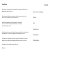
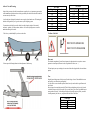
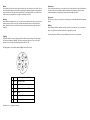
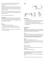
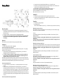
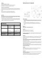
Manufacturer approved by ministerial decree for all trailers Technical Specifications And Operating Instructions RIBA bvba/sprl De Robianostraat 76-78 B – 2150 Borsbeek Tel. 03/321.70.04 Fax. 03/322.40.88 http://www.riba.be [email protected] Introduction Contents Dear customer, in order to ensure the safety and the correct operation of the trailer, we introduce some advise of use to you. Advise of Use and Warnings Please keep in mind, before you use the trailer for the first time to entirely read the directives of use and hold account of the technical data. Winches Before the mass production, our trailers are put at the test under the most severe conditions, and during manufacture they are constantly subjected to thorough controls. Axles Overrun Device So that this product keeps its qualities and performances,you should use only spareparts of the manufacturer. The user loses any guarantee if non-original parts are used. For all questions or commands concerning the spareparts, please indicate the reference number that you can find in our spareparts document on our website (www.riba.be). We thank you for the confidence that you testify to us. RIBA bvba. Coupling Head Troubleshooting Advise of Use and Warnings - Pay attention to the load of your trailer. Indeed, we easily forget the weight of the essential accessories : gasoline, oil 2 times, anchors, chains etc. It is excessively dangerous to exceed the authorized total weight of a trailer. Total Weight (kg) 2100 2000 1900 1600 1500 1400 1300 1100 - This is how you should ideally fix your boat on the trailer - Position of the hitch In spite of the great care with which we manufacture our trailers, it is very important to pay attention to their maintenance. Indeed, metals never had a great affinity for salted water and a trailer soaked in sea water can only suffer from it. - Avoid at the time of setting the boat into the water to put the wheels under water. The bearings and the brake will be grateful to you. It goes the same way for the lighting system. RT 3500 RT 2000 Max length (mm) 1300 1400 1435 1750 1820 1950 2100 2480 Total Weight (kg) 3500 3200 3000 2800 2600 Max length (mm) 1240 1350 1450 1550 1650 Please note - Please respect the following indication for the adjustment of the bow stop The chemical composition of the steel has an impact on the galvanization in a way that we cannot guarantee its visual aspect (difference in color, irregularities of surfaces, etc…). The load capacity can vary according to the execution of the trailer (length, width, axles and chosen options) Tires Regularly control the pressure of the tires as well as their degree of wear. Under-inflated tires wear more quickly, over-inflated tires could explode! A 8 years old tire or more should be replaced, indeed, not only wear but also the age influences the state of a tire! Do not forget to also control the sparewheel. Think of always taking along with you a jack in order to be able to change a wheel of your trailer. Try to use the jack of your car but it is probable that you cannot position it correctly. You would then be obliged to especially acquire a jack for your trailer. A small pneumatic jack can be very well placed under the frame of the trailer. Load Index 155 x 13 175 x 14 8 Ply 185 x 14 8 ply 195 x 14 8 ply 2,5 bar 4 bar - 4,2 bar 4 bar 4 bar - 4,2 bar Brakes Salted water If your trailer is slowed down, make control at least once the year the brakes of your trailer. You can control yourself the balancing of the brakes by tightening the hand brake slightly and by drawing the trailer with the hand. If this one swivels towards the left or the right-hand side, you can deduce from it that the brakes are not balanced. A passage in a workshop is essential ! After a setting into salted water, we can only advise you to rinse the trailer in order to eliminate sea salt. Indeed, this salt would quickly tackle the metal parts of the brakes and could if the trailer remained motionless a certain time block those with unforeseeable side effects ! Spare parts Bearings Make control the bearings once the year. You can also test yourself the bearings ! For that, put a jack under the trailer in order to raise a wheel, untighten the hand brake and seize the wheel with two hands, shake the wheel. If you feel that there is game, make control the bearings by a specialized workshop. We advise you to always carry with you a set of bearings. It is sometimes difficult to find spareparts abroad. Robbery Think of using an effective anti-theft system for your trailer. Our trailers are very coveted and it is always very unpleasant to not find its trailer after a splendid day on water The preceding advise will allow you to spend holidays that we wish you very pleasant. Lighting Frequently control the system of lighting. Indeed, the vibrations of the road as well as the settings into water can dammage the lighting. Often check connections with the car. There are excellent products in the trade to prevent this kind of problems (WD-40, CRC...). For long journey, always check that the lighting bar is well secured. 1 L Left flashing indicator (Yellow) 2 54G Fog lamp (White) 3 31 Mass (Green) 4 R Right flashing indicator (Blue) 5 58R (Black) 6 54 Stop light (Red) 7 58L Side-lights (Brown) Instructions for a 13 polig on the last page. Winches Installation Instructions Warning Always inspect the strap, rope, or cable and hook before each use. Never use straps, rope, or cable that is worn, frayed, or kinked. Never let anyone stand in or behind a boat while pulling with the winch. Do not stand near the winch strap, rope, or cable, because it can whip violently if it should break. Read and understand all instructions before using product. NEVER allow anyone unfamiliar with the operating instructions to use this product. Winches are not designed to secure boats to trailers while towing. Boat tie downs should be used for this purpose. If you cannot crank the winch with one hand, you are probably overloading the winch! High forces may be created by the use of a winch thereby creating potential safety hazards. Never let go of the handle until you are sure the ratchet pawl is properly set and supporting the load. If not, the handle can spin dangerously backwards. A clicking ratchet pawl when lowering the load will not support the load Winches that are equipped with a two way ratchet pawl system allow the convenience of bringing the line or strap onto either the top or bottom of the winch drum. IN NO CASE WILL THE RATCHET PAWL SYSTEM HOLD THE LOAD WHEN IT IS BEING LET OUT OR LOWERED. This winch is not designed to be a human or equipment hoist and should never be operated when there are persons positioned on or under the load being moved. The cable keeper or rope threading alone will not support the load. Never let the cable or rope all the way out. Always keep a minimum of three complete wraps of the cable or rope around the drum hub. On two speed winches make sure that the ratchet pawl is properly engaged to hold the load before attempting to change gears. Failure to follow these instructions may results in serious injury and/or property damage. Winch Applications All our trailer winches meet or exceed SAE Standard J1853. Those trailer winches are designed for use on boat trailers. To insure safer boat loading : The rated load capacity of the winch should at least equal to two times the maximum pull on the winch strap, rope or cable required to load the boat on the trailer. A general guide is for the winch rating to equal the total weight, including equipment. The breaking strength of the strap, rope, or cable should be at least 11/2 times the winch rating. Breaking strength of the hook should be 11/2 times the breaking strength of the strap or rope and 11/4 times the breaking strength of the cable. Single Speed Winches Easy to use one way ratchet pawl allows free wheeling in the OFF position. A convenient two way ratchet pawl offers the option of wrapping the line on the drum from either direction. (See the above warnings.) Two Speed Winches Larger boat load easily with two speed winches. One speed is for quick pull, and the other speed pulls heavy loads with less effort. Two speed winches allow changing speeds without removing the handle. Lift the shift lock lever and move the handle in or out to change speeds. Free wheeling line play-out without a spinning handle makes for safer operation. Optional hand brake may be purchased separately and can be installed after the winch is mounted. Light line The stand on wich this winch is mounted must be of adequate strength, and equal size to the base of the winch frame. Use three 3/8” diameter bolts in the slots in the base. Flat washers should be used under the heads of the bolts. When installing or replacing the strap or rope the drum assembly may be removed by removing the 3/8” capscrew. Gently spread the two cover halves apart just enough to slide the drum assembly out. After replacing the strap or rope, according to the instructions below, spread the cover halves apart and slide the drum assembly back into position. Make sure the drum spacer was included. Place the drum bolt with the stepwasher through the cover, frame, and drum assembly. Tighten the 3/8” locknut to 115 IN-LBS. Only winches that are designed to accommodate steel cable should bee used with steel cable. Strap The winches have the drums drilled for a strap cross bolt when using strapping (fig. 1). A hardened bolt, grade 5 or better, is recommended for strap mounting. Tighten the nut just to where end play in bolt is taken up. Overtightening can deform drum. Rope Attaching rope to the winch drum requires not bolts, nuts, or rope keepers. Two ways of threading the rope through drum side are shown (fig. 2). Maintain at least three complete wraps of rope around drum hub when under load. Calbe Pass cable through the hole in the drum side. Wrap cable around the drum hub onr turn. Continue inserting cable one inch past clamp location. Place keeper (clamp) washers and nuts on the outside of the drum (fig. 3). Top entry shown, bottom entry would be opposite. Maintain at least three complete wraps of the cable around drum hub when under load. Operating Instructions Single Speed Winches To pull line off : First place the ratchet pawl in the reverse or neutral position. To pull line off the winch, extreme caution must be exercised. Be certain that all persons and objects are clear of the area to insure that they will not be stuck and injured by a spinning winch handle as you pull line off the winch. To pull line/load in : First, ALWAYS ENGAGE THE RATCHET PAWL IN THE HOLD POSITION, this is done by aligning the engage arrow on the ratchet lever with the alignment marks on the frame. Before moving a load, make sure that the ratchet pawl snaps into engagement. Now turn the handle in the appropriate direction. When turning the handle you should always hear a clicking sound indicating the ratchet pawl is working properly. IF THE CLICKING SOUND SHOULD EVER STOP, DO NOT LET GO OF THE HANDLE BECAUSE THE HANDLE CAN SPIN DANGEROUSLY BACKWARDS. Lower or move the load to a safe resting place before letting go of the handle. Tot let line/load out : First, take a firm grip of the handle, then push the ratchet pawl to the reverse or neutral position. You may have to turn the handle slightly (pull line in) to free the ratchet pawl. Keep a firm grip on the handle and turn slowly. Never let go of the handle when letting out or lowering a load. If you want to stop and rest, always engage the ratchet pawl first, then let go of the handle gradually to make sure the ratchet pawl is holding the load. A clicking ratchet pawl when letting line/load out will not support the load. Axles Two Speed Winches The two speed winches change gear ratios by sliding the gear input shaft. When changing gears make sure that the ratchet pawl is properly engaged to hold the load before attempting to change gears. After the input shaft has been shifted to obtain the desired gear ratio, make sure the shift lock lever is firmly in place in the groove on the input shaft before operating the winch. To pull line off : shift input shaft to neutral position and engage shift lock when pulling line off drum. Place the ratchet pawl in the neutral position to pull line off the winch. Check position by turning handle to make sure the shaft does not turn with the handle. To pull line/load in : Follow the instructions for single speed winches. Hand Brake Operation For two speed winches equipped with the optional hand brake, when lowering a load you can push down on the hand brake lever and this will help let the line out more smoothly. This will reduce the effort required on the winch handle when letting line out, but NEVER let go of the winch handle. IN AN EMERGENCY, if the handle does spin backward, NEVER try to grab the handle. Maintenance The spur gears should have a film of grease on them at all times. Maintain a film of grease on outside diameter of drum support bolt for extended service life. Maintain a few drops of automotive engine oil on ratchet pawl mechanism and bushings for extended service life. The ratchet pawl mechanism must be clean and free of dirt, paint, ice, etc., as these conditions will prevent the ratchet pawl from operating properly. Safety Precautions No welding is permitted on the axles. It is most important that the wheel and hub/barke drum are dimensionally compatible. This means that the P.C.D., wheel bolts and inset must all be compatible with both the hub/brake drum and the wheel rim. Particular attention must be paid to the recommended torque figures for the wheel bolts. The axle type details shown on axle type shield must not be obscured or made illegible by the application of any additional surface finish. Operating Instructions Service Brake : When the towing vehicle is braking or travelling down the hill the overrun device shaft is pushed in (dependent on the magnitude of the thrust on the shaft) and presses on the overrun lever. This acts on the bowden cables and expander mechanism which in turn expands the brake shoes applying the wheel brakes. Reversing : When the towing vehicle is reversing, the overrun device shaft is pushed in, applying the brakes via the overrun lever, brake rod system, bowden cables and the expander mechanism. The backwards rotation of the brake drum causes the secondary brake shoe to collapse cancelling out the braking effect allowing the trailer to move backwards. At the same time the transmission lever swings back and compensates for the entire travel. Parking Brake : With the gas strut version pull the hand-brake lever over top dead centre. With the spring cylinder version pull the hand-brake lever right up to the last tooth. The trailer is then braked. Please note that with the handbrake fully applied the trailer is able to move backwards by 25cms until the spring cylinder/gas spring takes effect. Maintenance and Cleaning The axles that we use come fitted with maintenance free wheel bearings (greased and sealed for life) and no adjustment is necessary. N.B. The hub bearing is not protected against water ingress. Check wheel brake linings for wear every 10 000 kilometres or every 12 months via the inspection hole (Fig. 2/1). Adjust if necessary. Where continuous travel in hilly regions or high mileage is experienced earlier inspection and adjustment may be necessary. Note that travel of more than 60% of total overrun device shaft movement is indicative that brake adjustment is required. N.B. All necessary service work should only be carried out by trained personnel in specialist workshops. “Standard axle” maintenance – taper roller bearing After 1 500 km or 6 months have the axial play of the hub bearing checked and adjusted, if necessary. After 10 000 km or 12 months check quantity and quality of grease, renew if necessary. With boat trailers which are driven into water or sea water the hub bearing should be regreased shortly after contact with the water (with the exception of waterproof hubs). Check the wear of the wheel brake linings every 10 000 km or every 12 months through inspection hole and have adjusted, if necessary. Where continuous travel in hilly regions or high mileage is experienced earlier inspection and adjustment may be necessary. Note that travel of more than 60% of total overrun device shaft movement is indicative that brake adjustment is required. Troubleshooting Fault Cause Elimination Poor braking Linings are not fully bedded in Linings are damaged/dirty Friction losses too high, overrun device shaft corroded Only occurs when the braking system is set too tightly Auto-reverse lever is stuck Incorrect setting Braking system not fully released during forward travel Overrun lever stuck Wheel brake dirty Cable or bowden cable kinked Release springs defective or broken Rust deposit in brake drum(s) Will pass after braking a few times Have set replaced Ensure smooth action of transmission equipment including brake cable Re-adjust braking system Reversing heavy or blocked Brakes overheating when driving Steel spring axle maintenance – taper roller bearing Grease the 4 lubrication nipples of the steel spring axle every 5 000 km. Otherwise maintenance is as for standard axle. “Running or dead axle” maintenance After 1 500 km or 6 months Have the axial play of the hub bearing checked and adjusted, if necessary. With boat trailers which are driven into water or sea water the hub bearing should be regreased shortly after contact with the water (with the exception of waterproof hubs). Maintenance and care of galvanized vehicle parts The formation of white rust is only a blemish and can never be excluded completely. The following measures are necessary to minimise this as far as possible. Ensure an adequate air circulation during storage. Clean the galvanised surfaces with clear water (e.g. steam clean) after journeys in winter. Regrease and/or oil joints and bearing points! Spare Parts Replacement parts are safety critical parts. Should parts other than original parts be used then the warranty and product liability becomes void. In road traffic consequential damages including personal injuries are not to be underestimated. Please take this into account with spare parts! If repair work or servicing is required please contact us. Please bear in mind that repairs should only be carried out by trained and qualified workshops/personnel. To establish the correct spare parts required for your axle you should always quote the axle type (exle identification plate) and spare part identification number (ETI No.). This is imprinted on the wheel brake or on the identification plate. Please establish both these details before contacting us. Handbrake force low Uncomfortable ride or jerky braking Incorrect setting – friction losses too great Linings are not run in Friction losses too high Too much play in the braking system Shock absorber defective Restore to working order and lubricate Check brake adjustment Release hand-brake. Check transmission equipment (ensure smooth action) Check overrun lever Clean Renew bowden cable Renew springs Replace brake drum(s) and shoes, if necessary Check setting Will pass after breaking a few times Ensure smooth action of transmission equipment including bowden cable. (Oil) Check seting Have shock absorber checked and if necessary change Overrun Device Connect trailer electric plug controlling lights & indicators etc. to towing vehicle socket. Wind the jockey wheel up fully and clamp securely in position ensuring that it does not foul brake rod or breakaway cable. (See operating instructions for jockey wheel). Ensure handbrake is in the fully off position by pushing it right down. (See Fig. 3 – 6) CAUTION : failure to comply with this could result in the brakes overheating!! For details on the handbrake see section on Uncoupling. Remove wheel chocks and store or stow safely. Coupling Up Fully retract jockey wheel inner tube so that it locks against Jockey wheel outer tube. Slacken Jockey wheel locking handle and raise complete assembly through cutout in body to its highest possible position, lock handle (See Fig. 5A). Uncoupling Safety Precautions When parking your vehicle and trailer on site you must apply the trailer parking brake. If the trailer is parked and then disconnected from the towing vehicle it is recommended that each wheel is chocked using suitable wheel chocks. The tubular, “detachable” version must not be taken off with the hand-brake applied.µ CAUTION : please note when parking the trailer that the wheelbrake auto-reverse mechanism will allow the trailer to travel backwards for approximately 25 cm. (please allow sufficient clearance when parking.) Operation Secure trailer by chocking both wheels. Apply handbrake fully. There are 4 different handbrake systems (See Fig. 3 -6). With all four systems please observe the following: Handbrake lever with gas strut (Fig.3) : Ensure handbrake is fully applied (as highlighted). This will ensure that the gas strut will automatically reapply the wheel brakes if trailer starts to roll backwards. To release : Press the handbrake push button fully home and firmly press the handbrake lever back into the off position (handbrake horizontal). CAUTION : if the handbrake is not fully applied as detailed above there is a danger that the trailer could roll backwards! CAUTION : the brake rod must not be under tension/bowed when the handbrake is disengaged, otherwise the breakaway mechanism will not function. Ou roverrun devices are of the mechanica loverrun type using an hydraulic damper. Coupling Up Manoeuvre towing vehicle or trailer to couplingpoint. Overrun device fitted with 50mm coupling head : Fully open coupling head handle and securely hitch onto the towball of the towing vehicle. => See operating instructions for 50mm coupling head. Thread the breakaway cable through the breakaway cable guide provided (Fig. 2) and connect it to attachment point provided on towing bracket (Fig. 1). CAUTION : the breakaway cable must not wrapped around the jockey wheel as this disables the emergency brake (pic.2a). Furthermore the barkaway cable must be of sufficient length to avoid applying the emergency brake in advertently when cornering. The breakaway cable operates the hand-brake (emergency brake) in the event of the trailer becoming detached from the towing vehicle during towing. For this emergency brake to work correctly it is absolutely necessary that the breakaway cable runs through the breakaway cable guide and is not restricted in any way. Overrun device fitted with Eye End : Lock the eye end into the eye end jaw assembly => See operating instructions for vehicle eye end jaw assembly. Thread the breakaway cable through the breakaway cable guide provided (Fig. 2) and connect it to attachment point provided on towing bracket (Fig. 1). Take care that the breakaway cable is long enough to allow for cornering and will not become taut or snag during use, as this could result in handbrake operation whilst towing. The breakaway cable operates the handbrake (emergency brake) in the event of the trailer becoming detached from the towing vehicle during towing. For this emergency brake to work correctly it is absolutely necessary that the breakaway cable runs through the breakaway cable guide and is not restricted in any way. Overrun device fitted with 50mm coupling head/Eye End Handbrake lever with spring cylinder (Fig. 4) : Apply handbrake fully ensuring that handbrake is in the vertical position. This will ensure that the spring cylinder energy store is fully loaded and will automatically re-apply the wheel brakes if the trailer starts to roll backwards. CAUTION : if the handbrake is not fully applied as detailed above there is a danger that the trailer could roll backwards! To release : Press the handbrake push button fully home and firmly press the handbrake lever back into the off position (handbrake horizontal). Automatic handbrake lever (Fig.5) : Ensure handbrake is fully applied (as highlighted). This will ensure that the gas strut or spring cylinder will automatically re-apply the wheel brakes if trailer starts to roll backwards. CAUTION : if the handbrake is not fully applied as detailed above there is a danger that the trailer could roll backwards! To release : Firmly push the handbrake lever back into the off position (handbrake horizontal). Handbrake lever with spring cylinder and gas strut (Fig. 6) : Ensure handbrake is fully applied (as highlighted). This will ensure that the gas strut or spring cylinder will automatically re-apply the wheel brakes if trailer starts to roll backwards. CAUTION : if the handbrake is not fully applied as detailed above there is a danger that the trailer could roll backwards! To release : Press the handbrake push button fully home and firmly press the handbrake lever back into the off position (handbrake horizontal). Servicing Every 10 000 – 15 000 km or every 12 months : Lubricate/grease all sliding and moving parts of the overrun device as shown in Fig. 7. Recommended lubricant : general purpose grease to DIN 51825 KTA 3K4 Operating Instructions for Coupling Head Servicing and care of hot dip galvanized parts : The formation of white rust is only a surface coating and has no adverse effect on the anti-corrosion properties of galvanising. In order to minimise the potential for the formation of white rust the following precautions should be taken : Ensure there is an adequate air circulation when storing hot dip-galvanised parts. After winter journeys it is recommended that surfaces are washed with clean water. Spare Parts Replacement parts are safety critical parts. Should parts other than original spare parts be used then warranty and product liability becomes void. If repair work or servicing is required please contact us. Please bear in mind that repairs should only be carried out by trained and qualified personnel. To establish the correct spare parts required for your overrun device you should always quote the model and type of overrun device in question along with the ETI No. which is stamped into the overrun device housing (See Fig. 8). Please have this information readily available when ordering spare parts. Fault Cause Elimination Poor braking Overrun shaft/linkages tight Overrun shaft corroded Damage to body housing Handbrake not fully released Grease transmission system and all moving parts Release handbrake Check transmission system operates smoothly Wheel fouls brake rod Handbrake force low Uncomfortable ride Trailers brakes applied during deceleration or downhill travel Troubleshooting Brake overheating during towing Safety Precautions Gas strut defective Axle shock absorbers defective Overrun damper defective Check overrun lever moves freely Slacken locking handle and reposition assembly correctly Replace gas strut Replace shock absorbers Replace overrun damper Always ensure that the coupling head is properly connected to the towing vehicle’s towball every time you couple up. If not coupled up correctly the trailer may become detached from the towing vehicle and cause an accident! Maximum possible articulation of the coupling head must not exceed +/-25° vertically and +/-20° horizontally. If exceeded, components will be overloaded and the operation of the assembly adversely affected! Operation For types AK 75 / AK 160 / AK 300 / AK 350 : Articulation : Maximum articulation must not exceed +/-25° vertically (Fig. 1) Maximum articulation must not exceed +/-20° horizontally (Fig. 1) CAUTION : if these articulation angles are exceeded, components will be overloaded and the operation of the assembly adversely affected. Coupling Up : Open coupling head. To do this pull the coupling handle up (Fig. 2/1) in the direction of the arrow. The coupling mechanism has a fixed open position, i.e. as long as the coupling head is not placed on the ball the coupling handle will remain open. Put the open coupling on the ball of the towing vehicle. The nose load on the coupling head automatically and audibly clicks into position. In the interests of safety press the handle down by hand as well (Fig. 2/1). Locking and securing takes place automatically. The coupling ball is correctly connected when the green cylinder of the safety indicator is visible when the trailer coupling is viewed from the side (Fig. 2/2). The coupling mechanism is correctly engaged when the coupling handle can no longer be pressed down by hand. CAUTION : when the coupling head is not correctly hitched onto the towball then the trailer can become disconnected from the towing vehicle. Uncoupling : Open the coupling handle and lift the coupling head from the towball of the towing vehicle. Where there are higher nose loads coupling and uncoupling can be made easier by use of the jockey wheel. Wear indicator : A wear indicator on the coupling head (Fig. 3) shows wether the wear limit of the towing vehicle’s towball or the trailing coupling has been reached or not. For this purpose hitch up the trailer to the towing vehicle (see Coupling Up) and drive the car and the trailer approx. 500m. This will set the coupling head adjustment. Following this check wear as follows : If the green indicator on the coupling handle is completely covered over and only the red indicator visible (Fig. 3/1) this could be caused by the following : The towball has reached the lowest wear limit of dia. 49 Both coupling head and the towball are showing signs of wear Towball is in a new condition with dia. 50 but the coupling head is showing an excessive level of wear Servicing and Cleaning CAUTION : Under these circumstances the coupling head can become detached from the coupling ball and the trailer break away from the towing vehicle! The coupling head and towball must therefore be checked IMMEDIATELY before future use. Any faulty parts must be changed IMMEDIATELY. All maintenance work must be carried out by specialist workshops. Servicing and care of hot dip galvanized vehicle parts : The formation of white rust is only a surface coating and has no adverse effect on the anti-corrosion properties of galvanising. In order to minimise the potential for the formation of white rust the following precautions should be taken : For types AK 7 / AK 10/2 / AK 252 : Articulation : Maintain articulation angle at +/-25° vertically (Fig. 1) Maintain articulation angle at +/-20° horizontally (Fig. 1) CAUTION : if the articulation angle is exceeded, components will be overloaded. The function is no longer ensured! Coupling Up : Push the safety lever (Fig. 4/1) up with the index finger and lift the handle up and forwards. Put the opened coupling onto the towball with the handle pulled up and in addition press down by hand. The coupling will close by applying a light pressure. Press the handle down by hand until the catch (Fig. 4/3) snaps out. The coupling head is correctly engaged when the green edge of the wisual indicator is visible (Fig. 4/2). CAUTION : it is most important to check that the coupling head is properly engaged on the towball each time. Uncoupling : Lift coupling handle fully and remove the coupling head from the towball of the towing vehicle. Where there are higher nose loads, coupling and uncoupling can be made easier by use of the jockey wheel. Wear indicator : If the handle reaches back to the cutaway portion of the housing when the coupling head is engaged (Fig. 5) there will be play between the towball and the coupling head! Automatic readjustment is no longer possible and the assembly will require inspection. CAUTION : Under these circumstances the coupling head can become detached from the coupling ball and the trailer break away from the towing vehicle! The coupling head and towball must therefore be checked IMMEDIATELY before future use. Any faulty parts must be changed IMMEDIATELY. All maintenance work is to be carried out by specialist workshops. Lubricating points (Fig. 6) Clean towball coupling. Lightly grease, or oil ball socket, joints and bearing points as appropriate General purpose grease to DIN 51825 KTA 3K. Ensure there is adequate air circulation when storing the hot dip-galvanized parts After winter journeys it is recommended that surfaces are washed with clear water Troubleshooting Fault Cause Elimination Coupling does not engage when place don ball Ball diameter greater than 50 mm. Inner parts of the coupling are dirty or are not functioning correctly Ball deformed Change ball Clean and grease coupling, replace as necessary Align trailer and car and uncouple Grease/lubricate coupling mechanism Have coupling changed Have towball changed Trailer cannot be uncoupled Too much play in the coupling danger of trailer becoming unhitched Coupling worn out Articulation angle exceeded Rivet bent