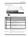
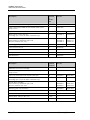
1
UltiMate 3000 Series SRD-3x00 Solvent Racks Operating Instructions Revision: 1.4 Date: January 2010 © 2010 Dionex Doc. No. 4820.3550 UltiMate 3000 Series: SRD-3x00 Solvent Racks Operating Instructions Declaration of Conformity Product: Solvent Rack Types: SR-3000, SRD-3200, SRD-3400, and SRD-3600 Dionex GmbH herewith declares conformity of the above products with the respective requirements of the following regulations: Low-Voltage Directive 2006/95/EC EMC Directive 2004/108/EC The electrical safety of the products was evaluated based on the following standard: EN 61010-1: 2002 Safety requirements for electrical equipment for measurement, control and laboratory use Part 1: General Requirements The Electromagnetic Compatibility (EMC) of the products was evaluated based on the following standards: DIN EN 61326: 2006 Electrical equipment for measurement, control and laboratory use EMC Requirements This declaration is issued for the manufacturer Dionex Softron GmbH Dornierstraße 4 D-82110 Germering by the President, Dr. Peter Jochum. January 15, 2010 Operating Instructions Page I UltiMate 3000 Series: SRD-3x00 Solvent Racks Page II Operating Instructions UltiMate 3000 Series: SRD-3x00 Solvent Racks Table of Contents 1 Introduction................................................................................................................... 1 1.1 1.2 1.2.1 1.2.2 1.2.3 1.3 1.4 2 Overview........................................................................................................................ 9 2.1 2.2 2.3 2.4 2.5 2.6 2.7 3 Unit Description..................................................................................................... 9 SRD Configurations............................................................................................... 9 Front Panel Elements ........................................................................................... 11 Rear Panel ............................................................................................................ 12 Fluid Connections ................................................................................................ 13 Leak Sensor.......................................................................................................... 14 Wellness............................................................................................................... 14 Installation................................................................................................................... 15 3.1 3.2 3.3 3.4 3.4.1 3.4.2 4 How to Use this Manual ........................................................................................ 1 Safety Information ................................................................................................. 2 Symbols on the Instrument and in the Manual ................................................. 2 General Safety Precautions............................................................................... 3 Consignes Générales de Sécurité .............................................................. 5 Intended Use .......................................................................................................... 7 Federal Communications Commission (FCC) Note ...................................... 7 Facility Requirements .......................................................................................... 15 Unpacking............................................................................................................ 15 Positioning the SRD in the UltiMate 3000 System ............................................. 17 Connecting the SRD ............................................................................................ 19 Connecting the SRD to an UltiMate 3000 System Pump............................... 19 Connecting the SRD to the Main Power Supply (Optional) .......................... 19 Preparation for Operation (Startup) ........................................................................ 21 4.1 Overview.............................................................................................................. 21 4.2 Connecting Drain Tubing .................................................................................... 21 4.3 Solvent Reservoirs ............................................................................................... 22 4.3.1 General Notes ................................................................................................. 22 4.3.2 Connecting the Solvent Reservoirs ................................................................ 23 4.3.3 Connecting the Solvent Lines from the Pump to the Degasser ...................... 25 5 Operation and Maintenance ...................................................................................... 27 5.1 5.2 Choosing the Solvents ......................................................................................... 27 General Notes for Degasser Operation ................................................................ 29 Operating Instructions Page i UltiMate 3000 Series: SRD-3x00 Solvent Racks 5.3 Operational Settings.............................................................................................30 5.3.1 Turning the Degasser on or off (from the UltiMate 3000 System Pump) ......30 5.3.1.1 Turning the Degasser on and off from the Pump Display .......................30 5.3.1.2 Turning the Degasser on and off in Chromeleon ....................................31 5.3.2 Turning the Degasser On or Off (Stand-alone Operation) .............................32 5.4 Special Chromeleon Functions ............................................................................33 5.4.1 Leak and Vacuum Monitoring........................................................................33 5.4.2 SRD Diagnostics.............................................................................................33 5.5 Shutting Down the SRD.......................................................................................34 5.6 Routine and Preventive Maintenance ..................................................................35 6 Troubleshooting ..........................................................................................................37 6.1 6.2 6.3 6.4 7 Overview..............................................................................................................37 Messages on the Pump Display ...........................................................................38 Chromeleon Diagnostics Message .......................................................................38 Operating Problems .............................................................................................39 Service ..........................................................................................................................43 7.1 7.2 7.3 General Notes.......................................................................................................43 Rinsing the Degassing Channels..........................................................................44 Eliminating Leakage in the Solvent Rack............................................................45 8 Technical Information ................................................................................................47 9 Accessories, Consumables, and Spare Parts ............................................................49 9.1 9.2 9.3 Standard Accessories ...........................................................................................49 Optional Accessories ...........................................................................................51 Consumables and Spare Parts ..............................................................................51 10 Pin Assignment............................................................................................................53 10.1 10.2 15-pin D-Sub Port ................................................................................................53 DC Input...............................................................................................................53 11 Index.............................................................................................................................55 Page ii Operating Instructions UltiMate 3000 Series: SRD-3x00 Solvent Racks 1 Introduction 1.1 How to Use this Manual The layout of this manual is designed to provide quick reference to the sections of interest to the reader. However, in order to obtain a full understanding of the Solvent Rack, Dionex recommends that you review the manual thoroughly before beginning operation. Almost all descriptions in the manual apply to all models in the UltiMate 3000 SRD-3x00 Solvent Rack series. Therefore, the term "the SRD" is used throughout the manual. If some detail applies to only one model, the model is identified by name. Note: The device configuration may vary; therefore, not all descriptions necessarily apply to your particular instrument. The software descriptions in this manual refer to Chromeleon 6.80 Service Release 8. The information contained in this manual is subject to change without notice and should not be construed as a commitment by Dionex. Dionex assumes no responsibility for any errors that may appear in this document. This document is believed to be complete and accurate at the time of publication. In no event shall Dionex be liable for incidental or consequential damages in connection with or arising from the use of this document. The information contained in this document is subject to change without notice. CHROMELEON® and UltiMate® (US) are registered trademarks of Dionex. All other trade or company names mentioned are subject to the copyright and the property and trademark rights of the respective companies. All rights reserved, including those for photomechanical reproduction and storage on electronic media. No part of this publication may be copied or distributed, transmitted, transcribed, stored in a retrieval system, or transmitted into any human or computer language, in any form or by any means, electronic, mechanical, magnetic, manual, or otherwise, or disclosed to third parties without the express written permission of Dionex. Operating Instructions Page 1 UltiMate 3000 Series: SRD-3x00 Solvent Racks 1.2 Safety Information The CE Mark label and cTUVus Mark safety label on the instrument indicate that the instrument is compliant with the related standards. 1.2.1 Symbols on the Instrument and in the Manual The table shows the symbols used on the instrument: Symbol Description ˜ Alternating current—Courant alternatif Refer to the Operating Instructions to prevent risk of harm to the operator and to protect the instrument against damage. Référez-vous à ce manuel pour éviter tout risque de blessure à l'opérateur et/ou protéger l'instrument contre tout dommage Label according to the "Measures for Administration of the Pollution Control of Electronic Information Products" (China RoHS) guideline Étiquette "Measures for Administration of the Pollution Control of Electronic Information Products" (China RoHS) WEEE (Waste Electrical and Electronic Equipment) label—For more information, see the WEEE Information section in the "Installation and Qualification Documents for HPLC Systems" binder. Étiquette WEEE (Waste Electrical and Electronic Equipment) —Pour plus d'informations, référez-vous au chapitre WEEE Information dans le classeur "Installation and Qualification Documents for HPLC Systems" At various points throughout the manual, messages of particular importance are indicated by certain symbols: Tip: Indicates general information, as well as information intended to optimize the performance of the instrument. Important: Indicates that failure to take note of the accompanying information could cause wrong results or may result in damage to the instrument. Important: Indique que ne pas tenir compte de l'information jointe peut conduire à de faux résultat ou endommager l'instrument. Warning: Indicates that failure to take note of the accompanying information may result in personal injury. Avertissement: Indique que ne pas tenir compte de l'information jointe peut entraîner des blessures corporelles. Page 2 Operating Instructions UltiMate 3000 Series: SRD-3x00 Solvent Racks 1.2.2 General Safety Precautions When working with analytical instrumentation, you should know the potential hazards of using chemical solvents. Tips: Before initial operation of the SRD, make sure that you are familiar with the contents of this manual. Observe any warning labels on the device and see the related sections in these Operating Instructions. To avoid the possibility of personal injury or damage to the instrument, observe the following general safety precautions when operating the instrument or carrying out any maintenance work: Install the HPLC system in a well-ventilated laboratory. If the mobile phase includes volatile or flammable solvents, do not allow them to enter the workspace. For minimum interference effects, all components of the analytical system should be connected to the same mains output (same phase). The front panel tilts upward. When lifting or moving the SRD, always lift by the bottom or sides of the instrument. This is to avoid damage to the instrument. For safety reasons, you should not lift the SRD with one or more solvent reservoirs being in the tray. The open front panel door is not designed to carry weight. Therefore, you should not place any objects on the open front panel door. Always set a lower pressure limit for the HPLC pump. This prevents damage resulting from leakage or from running the pump dry. If the mobile phase includes volatile or flammable solvents, avoid open flames and sparks. If a leak occurs, turn off the SRD and remedy the situation immediately. Replace faulty power cords and communication cables. Many organic solvents and buffers are toxic. Know the toxicological properties of all mobile phases that you are using. The toxicological properties of many samples may not be well known. If you have any doubt about a sample, treat it as if it contains a potentially harmful substance. Wear goggles when handling mobile phases or operating the instrument. An eyewash facility and a sink should be close to the unit. If any mobile phase splashes on the eyes or skin, wash the affected area and seek medical attention. Operating Instructions Page 3 UltiMate 3000 Series: SRD-3x00 Solvent Racks Dispose of waste mobile phase in an environmentally safe manner that is consistent with all local regulations. Do not allow flammable or toxic solvents to accumulate. Follow a regulated, approved waste disposal program. Never dispose of flammable or toxic solvents through the municipal sewage system. Use only standard solvents (HPLC grade) and buffers that are compatible with all parts that may be exposed to solvents ( page 47). In an UltiMate 3000 system, some components are made of PEEK. While this polymer has superb chemical resistance to most organic solvents, it tends to swell when in contact with trichlormethane (CHCl3), dimethyl sulfoxide (DMSO), or tetrahydrofuran (THF). In addition, it is attacked by concentrated acids, such as, sulfuric acid and nitric acid or a mixture of hexane, ethyl acetate, and methanol. (Swelling or attack by concentrated acids is not a problem with brief flushing procedures.) Do not use PEEK tubing that is stressed, bent, or kinked. Wear goggles when handling fused silica tubing (during installation, cutting, etc.) Before interrupting operation for several days or more, observe the precautions on page 34. Use original Dionex spare parts only. Substituting non-Dionex parts or using non-Dionex accessories may impair the performance of the SRD. Do not use the SRD in ways other than those described in these operating instructions. Page 4 Operating Instructions UltiMate 3000 Series: SRD-3x00 Solvent Racks 1.2.3 Consignes Générales de Sécurité Veuillez noter: Avant de commencer à utiliser l'instrument, assurez-vous que vous vous êtes familiarisés avec le contenu de ce manuel. Observez les étiquettes d'avertissement sur l'appareil et référez-vous aux sections correspondantes dans ce mode d'emploi. Veuillez observer les consignes générales de sécurité suivantes lorsque vous utilisez l'instrument ou que vous procédez à des opérations de maintenance: Installez le système HPLC dans un laboratoire bien ventilé. Si la phase mobile contient des solvants volatils ou inflammables, empêchez qu'ils ne pénètrent dans l'espace de travail. Afin d'éviter au maximum les interférences, tous les éléments du système analytique doivent être raccordés à la même ligne secteur (même phase). Lorsque vous soulevez ou l’instrument, tenez-le toujours par le dessous ou par les côtés de l'unité. Soulever l’instrument par la partie avant inférieure ou par le panneau avant peut endommager la porte. Pour raison de sécurité, ne soulevez pas l'instrument avec des réservoirs. Ne placez aucun objet lourd sur la porte ouverte du panneau avant. Ceci pourrait endommager la porte. Réglez toujours une limite de pression minimum pour le système HPLC. Ceci prévient les dommages résultant de fuites ou du fonctionnement à sec de la pompe. Si la phase mobile contient des solvants volatils ou inflammables, évitez les flammes nues et les sources d’étincelles à proximité. Si une fuite se produit, arrêtez immédiatement l’instrument et remédiez au problème. Remplacez les cordons d'alimentation électrique et les câbles de communication défectueux. De nombreux solvants organiques et solutions salines sont toxiques. Informez-vous des propriétés toxicologiques de toutes les phases mobiles que vous utilisez. Les propriétés toxicologiques de nombreux échantillons peuvent être mal connues. Au moindre doute concernant un échantillon, traitez-le comme s'il contenait une substance potentiellement dangereuse. Operating Instructions Page 5 UltiMate 3000 Series: SRD-3x00 Solvent Racks Portez des lunettes de protection lorsque vous manipulez des phases mobiles ou que vous utilisez l'instrument. Une installation permettant de se laver les yeux ainsi qu'un lavabo doivent se trouver à proximité du système. Si une phase mobile, quelle qu'elle soit, entre en contact avec vos yeux ou votre peau, rincez abondamment la zone affectée à l’eau, puis. Débarrassez-vous de tous les déchets de phase mobile de manière écologique, conformément à la règlementation en vigueur au niveau local. Empêchez impérativement l'accumulation de solvants inflammables et/ou toxiques. Suivez un programme d'élimination des déchets règlementé et approuvé. Ne jetez jamais de solvants inflammables et/ou toxiques dans le système municipal d'évacuation des eaux usées. Utilisez uniquement des solvants (qualité HPLC) et des solutions salines compatibles avec les matériaux exposés phase mobiles ( page 47). Dans un système UltiMate 3000, certaines composantes sont en PEEK. Bien que ce polymère présente une excellente résistance chimique à la plupart des solvants organiques, il a tendance à gonfler lorsqu'il est en contact prolongé avec du chloroforme (CHCl3), du diméthyle sulfoxyde (DMSO) ou du tétrahydrofurane (THF). De plus, il est attaqué par des acides concentrés tels que l'acide sulfurique et l'acide nitrique ou d'un composé du hexane, éthyle acétate et méthanol. (Ces acides peuvent cependant être utilisés dans le cadre de procédures de nettoyage, à condition que l’exposition soit brève.) N'utilisez pas de tubes PEEK écrasés, pliés ou abimés. Portez des lunettes de protection lorsque vous manipulez des capillaires en silice fondue (pendant l'installation, découpe, etc.). Avant d'interrompre le fonctionnement pendant plusieurs jours ou plus, observez les précautions figurant sur la page 34. Utilisez des pièces de rechange d'origine Dionex. Effectuer des remplacements par des pièces ne provenant pas de Dionex ou utiliser des accessoires ne provenant pas de Dionex peut affecter les performances de l'instrument. N'utilisez pas l'instrument de manière autre que celles décrites dans ce manuel. Page 6 Operating Instructions UltiMate 3000 Series: SRD-3x00 Solvent Racks 1.3 Intended Use The SRD has been developed as part of the UltiMate 3000 system and is a reliable module for the secure and functional positioning of the solvent reservoirs and for automatic degassing of typical HPLC (high performance liquid chromatography) solvents. The SRD is controlled by the Chromeleon Chromatography Management System from the HPLC pump of the UltiMate 3000 series. However, the SRD can be used with other HPLC systems if adequate control inputs and outputs are available. Being part of the UltiMate 3000 system, the SRD (and the pump) can also be operated with other data systems, such as Analyst® (Applied Biosystems/MDS Sciex), Compass™/ HyStar™ (Bruker Daltonics), or Xcalibur™ (Thermo Scientific). To do so, installation of the DCMSLink (Dionex Chromatography Mass Spectrometry Link) software is required in addition to the installation of the data system. Operation in stand-alone mode is possible as well. Please note that the SRD may be operated only by using Dionex accessories and spare parts ( page 49) and within its technical specifications ( page 47). If there is any question regarding appropriate usage, contact Dionex before proceeding. Dionex cannot be held liable for any damage, material or otherwise, resulting from inappropriate or improper use of the instrument. 1.4 Federal Communications Commission (FCC) Note This equipment has been tested and found to comply with the limits for a Class A digital device, pursuant to part 15 of the U.S. FCC Rules. These limits are designed to provide reasonable protection against harmful interference when the equipment is operated in a commercial environment. This equipment generates, uses, and can radiate radio frequency energy and, if not installed and used in accordance with the instruction manual, may cause harmful interference to radio communications. Operation of this equipment in a residential area is likely to cause harmful interference, in which case the user will be required to correct the interference at his expense. Operating Instructions Page 7 UltiMate 3000 Series: SRD-3x00 Solvent Racks Page 8 Operating Instructions UltiMate 3000 Series: SRD-3x00 Solvent Racks 2 Overview 2.1 Unit Description The SRD is a modern high-quality instrument designed for HPLC analysis, especially as part of the UltiMate 3000 system. The SRD provides a secure location for installation of the solvent reservoirs and, when mounted on top of the UltiMate 3000 system, saves valuable bench space. The SRD includes a reservoir tray, solvent reservoirs, and appropriate tubing. The integrated analytical vacuum degasser continuously degasses solvents through special polymer membranes that are permeable to gas, but not to liquids. Degassing solvents guarantees reproducibility and reduces pulsation in the connected pump. All parts in the flow path are made of Teflon® AF, PEEK, FEP, and Tefzel® (filter frit in the inline filter: stainless steel or titanium) to provide optimum resistance to the most commonly used HPLC solvents and buffer solutions. 2.2 SRD Configurations The SRD is available in the following configurations: SRD Description Part No. SRD-3600 SRD with analytical 6-channel vacuum degasser typically for use with the following pumps: - one DGP-3600 - two HPG-3200 pumps in a two-stack system - one HPG-3200 and one HPG-3400 in a two-stack system - one HPG-3400 if you want to degas the solvents and the wash liquid of the UltiMate 3000 autosampler. 5035.9230 SRD-3400 SRD with analytical 4-channel vacuum degasser typically for use with the following pumps: - one HPG-3400 - two HPG-3200 pumps in a two-stack system - one HPG-3200 or ISO-3100 if you want to degas the solvents and the wash liquid of an UltiMate 3000 series autosampler - one NCS-3500RS 5035.9245 SRD-3200 SRD with analytical 2-channel vacuum degasser typically for use with the following pumps: - one HPG-3200 - one ISO-3100 5035.9250 Operating Instructions Page 9 UltiMate 3000 Series: SRD-3x00 Solvent Racks In addition, a solvent rack without degasser channels is available (SR-3000, part no. 5035.9200). The SR-3000 is intended only for use as a solvent organizer, for example, together with an LPG-3400 pump. For this pump type, the degasser is incorporated in the pump. Tip: Page 10 An SRD with an analytical degasser cannot be used with a semipreparative pump. Operating Instructions UltiMate 3000 Series: SRD-3x00 Solvent Racks 2.3 Front Panel Elements 1 2 Fig. 1: Front panel view No. 1 2 Front Panel Element Description LEDs Power The LED is blue when the SRD power is on. Vacuum The LED is green if the degasser is working properly. The LED is red if the degasser vacuum is insufficient for proper degassing. In this case, also the Status LED is red Status The LED is green if the degasser is working properly and no leaks have been detected. The LED is red if the leak sensor reports a leak. The Vacuum and Status LEDs are red if the degasser vacuum is insufficient for proper degassing. Standby button Switches the SRD to standby mode. The LED of the standby-button is red when the SRD is in standby mode. To resume operation, press the standby button again (the LED is not lighted). Note: To allow the SRD to change the mode, press and hold the Standby button for at least 1 second. Important: If you switch a pump to which an SRD-3x00 Solvent Rack is connected to the Standby mode, the Solvent Rack, too, will be set to Standby mode. Important: Si vous commutez une pompe à laquelle est raccordé un dégazeur SRD, en mode Veille, le dégazeur passera également en mode Veille. Operating Instructions Page 11 UltiMate 3000 Series: SRD-3x00 Solvent Racks 2.4 Rear Panel 2 1 Fig. 2: Rear panel view No. Description 1 15-pin D-Sub port: Connects the SRD to the pump ( page 19) 2 DC Input (Power) Only to be used if the SRD is not controlled by the UltiMate 3000 system pump. In this case, connect an external power supply unit (part no. 6510.0004) from here to the main power supply ( page 19). Page 12 Operating Instructions UltiMate 3000 Series: SRD-3x00 Solvent Racks 2.5 Fluid Connections The front panel door tilts upward to provide easy access to the fluid connections in the SRD. The open door locks in its topmost position. 1 2 Fig. 3: SRD with open front panel door (here SRD-3600) No. 3 Description 1 Exhaust air outlet Optional: Connect tubing to vent vapors exiting the degassing chambers. 2 Tubing guides for the solvent lines 3 Leak sensor ( page 14) Warning: For safety reasons, you should not lift the SRD with one or more solvent reservoirs being in the tray. Avertissement: Pour raison de sécurité, ne soulevez pas l'instrument avec des réservoirs. Important: Do not lift the SRD by the front panel door. When lifting or moving the SRD, always lift by the bottom or sides of the instrument. Lifting the SRD by the front panel may damage the front panel door. The open front panel door is not designed to carry weight. Therefore, you should not place any objects on the open front panel door. Important: Lorsque vous soulevez ou l’instrument, tenez-le toujours par le dessous ou par les côtés de l'unité. Soulever l’instrument par la partie avant inférieure ou par le panneau avant peut endommager la porte. Ne lacez aucun objet sur la porte ouverte du panneau avant. Ceci peut endommager la porte. Operating Instructions Page 13 UltiMate 3000 Series: SRD-3x00 Solvent Racks 2.6 Leak Sensor A leak sensor is installed inside the SRD. If liquid collects in the drip tray under the fluid connections, the leak sensor reports a leak, and the Status LED on the front panel door changes to red. If the SRD is operated from a pump of the UltiMate 3000 system, a message (Solvent Rack leak detected) appears on the front panel display of the pump. When the pump is operated by Chromeleon, and if the leak sensor is exposed to liquids for at least 10 minutes, the related message is displayed also in the Chromeleon Audit Trail. When the leak sensor reports a leak, eliminate the cause for the leakage and dry the leak sensor ( page 45). 2.7 Wellness System Wellness monitors the health of the SRD. Therefore, the SRD supports several performance and reliability features that can help you detect small problems before they turn into big ones: Leak detection–Status LED on the front panel door Degasser vacuum level monitoring–Status and Vacuum LEDs on the front panel door When an error is detected, the Status LED or the Status and Vacuum LEDs on the front panel door change to red. If the SRD is connected to an UltiMate 3000 system pump that is operated with Chromeleon, the associated message appears on the pump display and also in the Chromeleon Audit Trail ( page 37). Page 14 Operating Instructions UltiMate 3000 Series: SRD-3x00 Solvent Racks 3 Installation 3.1 Facility Requirements Make sure that the installation site meets the power and environmental specifications listed in the Technical Information section ( page 47). Install the SRD in the laboratory on a stable surface that is free of vibrations. Typically, the SRD is placed on top of the pump. Make sure that the surface is resistant to solvents. Avoid locations with extreme changes in temperature. Avoid locations with extreme changes in temperature (such as direct sunlight or drafts) and high humidity. Allow sufficient clearance behind and to the sides of the SRD for power connections and ventilation. 3.2 Unpacking All electrical and mechanical components of the SRD are carefully tested before the instrument is shipped from the factory. After unpacking, inspect the SRD for any signs of mechanical damage that may have occurred during transit. Tips: Immediately report any shipping damage to both, the incoming carrier and Dionex. Shipping insurance will compensate for the damage only if reported immediately. Keep the original shipping container and packing material. They will provide excellent protection for the SRD in case of future transit. Shipping the unit in any other packaging automatically voids the product warranty. 1. Place the shipping container on the floor. Remove the accessories kit 2. Grasp the SRD by the sides. Slowly and carefully, pull the SRD out of the shipping container and place it on a stable surface Important: To prevent the SRD from falling, grasp the SRD by the sides, and then lift the SRD together with the foam spacers out of the shipping container. Do not lift the SRD by the foam spacers or the front panel. Operating Instructions Page 15 UltiMate 3000 Series: SRD-3x00 Solvent Racks Important: Afin d'empêcher l'instrument de tomber, saisissez-la par les côtés. Ne soulevez l'instrument à l’aide du matériau d'emballage ou par la porte du panneau avant. 3. Remove the foam spacers, and then remove the polythene packaging. 4. Before connecting the SRD to the power source, wait approximately 4 hours to allow the instrument to come to room temperature and to allow any condensation that might have occurred during shipping to evaporate. After 4 hours, check the SRD; if condensation still exists, allow the SRD to continue to warm up (without connecting it to the power source) until the condensation is completely gone. Page 16 Operating Instructions UltiMate 3000 Series: SRD-3x00 Solvent Racks 3.3 Positioning the SRD in the UltiMate 3000 System If the SRD is part of an UltiMate 3000 system, for example, for analytical HPLC applications, Dionex recommends that you stack the individual modules, for example, as shown in Fig. 4 and interconnecting them on the rear panel as shown in Fig. 5. However, the arrangement of the system modules depends on the application. Solvent Rack Pump Autosampler Column compartment Detector Fig. 4: Module arrangement for an UltiMate 3000 system (example) If the solvent rack is part of an UltiMate 3000 RSLCnano system or Proteomics MDLC system, the related system manual provides information about how to arrange the modules and set up the system for these applications. Operating Instructions Page 17 UltiMate 3000 Series: SRD-3x00 Solvent Racks Solvent Rack Pump (here RS pump) Autosampler Column compartment Detector (here DAD-3000/ MWD-3000) Fig. 5: Example for the rear panel connections on an UltiMate 3000 system Apart from the Solvent Rack, all modules of the UltiMate 3000 system can be connected separately to the Chromeleon computer by using the USB port on the rear panel of the instrument. However, Dionex recommends interconnecting all modules, and then connecting the system to the Chromeleon computer by using only one connection. For systems with a DAD-3000(RS) or MWD-3000(RS), you can use only the hub on the detector for the connection. For systems with a VWD-3x00(RS), only use the hub on the pump. Page 18 Operating Instructions UltiMate 3000 Series: SRD-3x00 Solvent Racks 3.4 Connecting the SRD 3.4.1 Connecting the SRD to an UltiMate 3000 System Pump Locate the connection cable in the accessories kit for the SRD and connect the 15-pin DSub port on the rear panel of the SRD with the Solvent Rack port on the rear panel of the pump. To ensure trouble-free operation, use only the cable shipped with the instrument. When the SRD is connected to the pump, the solvent rack is powered from the pump. The SRD must not be connected directly to the main power supply. For information about the pin assignment for the 15-pin D-Sub connector, see page 53. 3.4.2 Connecting the SRD to the Main Power Supply (Optional) The SRD needs to be connected to the main power supply only if it is not operated from an UltiMate 3000 system pump. For this scenario, an external power supply (part no. 6510.0004) is available from Dionex as an option for the SRD. Use the external power supply unit to connect the DC input on the rear panel of the SRD to a power source that is connected to a true ground. No manual adjustment is required to adapt the line voltage to local voltage requirements. Important: Do not connect the external power supply unit when the SRD is connected to an UltiMate 3000 system pump ( section 3.4.1). Important: N'utilisez pas d'alimentation électrique externe si l'instrument est raccordé un pompe du système UltiMate 3000 ( chapitre 3.4.1). Operating Instructions Page 19 UltiMate 3000 Series: SRD-3x00 Solvent Racks Page 20 Operating Instructions UltiMate 3000 Series: SRD-3x00 Solvent Racks 4 Preparation for Operation (Startup) 4.1 Overview After you have unpacked, positioned, and connected the SRD described in sections 3.1 through 3.4 ( page 15 and following pages), prepare the SRD for operation: 1. Connect drain tubing ( section 4.2). 2. Connect the solvent reservoirs, and then connect the solvent lines to the degassing channels ( page 22). 3. Select one of the following alternatives: To operate the SRD with the pump of the UltiMate 3000 System Connect the pump to the degassing channels ( page 25). To operate the SRD stand-alone Connect the degassing channels as required by your application. 4.2 Connecting Drain Tubing To discharge liquid leaks that might have accumulated in the interior, the SRD has a drain port at the bottom right of the instrument. Fig. 6: Drain port Direct liquid leaks to waste through the drain system of the UltiMate 3000 system, by using the components from the drain kit. The components required for connecting the drain tubing are shipped with the UltiMate 3000 pumps and the NCS-3x00RS, but can be ordered also separately. The drain kit (part no. 6040.0005) includes all required components and detailed installation instructions. Operating Instructions Page 21 UltiMate 3000 Series: SRD-3x00 Solvent Racks 4.3 Solvent Reservoirs All Solvent Racks are shipped with solvent reservoirs and appropriate tubing, including frit holders with filter frits. 4.3.1 General Notes When connecting the solvent reservoirs, observe the following general precautions: Observe the precautions for solvent selection ( page 27). Always install filter frits on the solvent lines. This prevents contaminants from reaching the HPLC system that may increase wear and cause damage to the system. Regularly check the filter frits for permeability. This is especially important when using aqueous solvents. Aqueous solvents may contaminate the filters with algae and other microorganisms that deposit on the filter frits. Therefore, also replace the solvents at regular intervals. Rinse the reservoirs thoroughly before refilling them. Replace the filter frits as necessary As a standard, filter holders with 10 µm stainless steel frits are provided in the accessories kit for the Solvent Rack. Do not use these frits if the system includes a biocompatible pump or NCS-3x00RS. Replace the stainless steel frits with the titanium frits from the accessories kit of the pump or NCS. Open the filter holder and remove the filter frit. When placing the new filter frit into the bottom part, make sure that the frit is in a level position (avoid tilting the frit). Make sure that the tubing connecting the pump to the degasser is as short as possible and locate the solvent reservoirs as close as possible to the pump. To avoid formation of gas bubbles in the reservoirs and reformation of gas bubbles in the solvent, make sure that the reservoirs are on the same level or higher as the pump. Therefore, stack the rack onto the pump as shown in Fig. 4 ( page 17). Normal phase eluents usually show only a low concentration of dissolved gases. Therefore, it is normally not required to use a degasser with these eluents. Before connecting the solvent lines, make sure that the connectors are free of contaminants. Even minute particles can allow air to enter the degasser, and thus reduce the degassing effectiveness. Page 22 Operating Instructions UltiMate 3000 Series: SRD-3x00 Solvent Racks When replacing solvents, make sure that the solvents are miscible. Mix immiscible solvents with an intermediate solvent (for example, isopropanol) to replace them step-bystep. Tip: If the UltiMate 3000 system includes an UltiMate 3000 series autosampler, Dionex recommends degassing the wash liquid on a continuous basis, for example, by using the degasser of an appropriate SRD. The procedure how to prepare and install the wash liquid lines is similar to the connecting the solvent lines. For details, see the Operating Instructions for the autosampler. 4.3.2 Connecting the Solvent Reservoirs 1. Feed the solvent line through the retaining guide, which holds the tubing in place in the bottle, and then into the open hole in the reservoir cap. 2. Verify that an appropriate frit is installed in the filter holder. Pump Filter Frit Part No. RS and SD pumps Stainless steel, porosity: 10 µm 6268.0110 BM pumps and NCS-3x00RS Titanium, porosity: 2 µm 6268.0117 AB pumps Titanium, porosity: 10 µm 6268.0111 3. Slide the filter holder with filter frit onto the end of the solvent line. 4. If required Cut the tubing straight if necessary. The end of the solvent line should be cut straight and not deformed. Use only the original Dionex solvent lines. 5. Place the entire assembly in the solvent reservoir. 6. Tighten the reservoir cap hand-tight. Retaining guide Filter holder with filter frit Fig. 7: Connecting the solvent lines to the reservoirs When replacing a solvent line, remove the frit first, then the solvent line, and then the retaining guide. 7. Connect the lines to the appropriate connection ports on the degassing module. Route the solvent lines through the opening between the housing and the front panel door. Operating Instructions Page 23 UltiMate 3000 Series: SRD-3x00 Solvent Racks Fig. 8: Opening for the solvent lines 8. Remove the blind fitting from the degasser inlet if necessary and connect the solvent line with the associated line label. A B C A B C Degasser inlets (solvent line connection) Degasser outlets (to pump) Tubing guides Fig. 9: Example for degasser connections (here SRD-3600) Tip: The degasser ports in the upper row are combined in pairs with the related ports in the lower row. Before connecting the solvent lines, make sure that the connectors are free of contaminants. Even minute particles can allow air to enter the degasser, and thus reduce the degassing effectiveness. 9. Connect the solvent lines from the pump to the degasser ( page 25). Page 24 Operating Instructions UltiMate 3000 Series: SRD-3x00 Solvent Racks 4.3.3 Connecting the Solvent Lines from the Pump to the Degasser With all UltiMate 3000 system pumps, the solvent supply lines are connected to the pump at the factory. 1. If necessary, route the solvent lines through the opening between the front panel door and top cover ( Fig. 10). Pump housing The solvent lines are routed through this opening. Pump door Fig. 10: Preconnected solvent lines (here on a DGP-3600) 2. Tubing guides in the SRD facilitate the connection of the solvent lines ( Fig. 9, page 24). Place the solvent line in a tubing guide, remove the blind fitting from the associated degasser outlet if necessary ( Fig. 9), and connect the solvent line with the associated line label. 3. Locate the solvent reservoirs as close as possible to the pump. To avoid formation of gas bubbles in the reservoirs and reformation of gas bubbles in the solvent, make sure that the reservoirs are on the same level or higher as the pump. Therefore, stack the SRD onto the pump as shown in Fig. 4 ( page 17). The tubing connecting the pump to the degasser should be as short as possible to avoid reformation of gas bubbles in the solvent. Operating Instructions Page 25 UltiMate 3000 Series: SRD-3x00 Solvent Racks Page 26 Operating Instructions UltiMate 3000 Series: SRD-3x00 Solvent Racks 5 Operation and Maintenance 5.1 Choosing the Solvents Observe the following precautions: Use only water of at least HPLC grade or better LC-MS grade (0.2 µm, filtered). If water from water purification systems is used that are not properly maintained, polymeric contamination may seriously damage the column, rapidly block solvent frits, and result in early piston seal wear. Use only standard solvents and buffers that are compatible with all parts of the UltiMate 3000 system that may be exposed to solvents. For information about the wetted parts in the Solvent Rack, see the Technical Information section ( page 47). For information about the wetted parts in the other UltiMate 3000 system modules, refer to the 'Technical Information' section in the operating instructions for the modules. Make sure to use special (highly pure) solvents. They are usually labeled accordingly by the vendor. Mind the special properties of the solvents, such as viscosity, boiling point, UV absorption (UV/VIS detector), refractive index (refractive index detector), and dissolved gas (degasser). Buffer concentration: Typically up to 1 mol/L (< 0.1 mol/L chloride ions). pH range: 1 through 13 In rare cases, reactions with the stainless steel or titanium have been observed for pH values < 3 in combination with special solvents and longer application times. Therefore, you should purge the system thoroughly after these applications and monitor the system behavior. Observe the solvent compatibility of the degasser. Whenever possible, avoid using the following solvents: hexafluoroispropanol, hydrofluorid containing solvents, perfluorinated solvents, and freons. The UltiMate 3000 series pumps are shipped with reversed phase piston seals (RP). Keep in mind that using chloroform, trichlorobenzene, methylene chloride, tetrahydrofuran, or toluene as solvents chemically damages the UHMW-PE seals. Chemical reactions may also occur when using tetrachloromethan, diethyl ether, ethyl ether, di-isopropyl ether, ketones, methylbenzene, methycyclohexane, and monochlorobenzene. If you use these solvents, contact your Dionex sales representative. In an UltiMate 3000 system, some components are made of PEEK. While this polymer has superb chemical resistance to most organic solvents, it tends to swell when in contact with trichlormethane (CHCl3), dimethyl sulfoxide (DMSO), or tetrahydrofuran (THF). In addition, it is attacked by concentrated acids, such as, sulfuric acid and nitric acid or a Operating Instructions Page 27 UltiMate 3000 Series: SRD-3x00 Solvent Racks mixture of hexane, ethyl acetate, and methanol. (Swelling or attack by concentrated acids is not a problem with brief flushing procedures.) Before switching from buffer to organic solution, rinse the system thoroughly with deionized water. When switching to another solvent, ensure that the new solvent is miscible with the one contained in the system. Otherwise, for example, the pump can be damaged by flocculation. After operation, rinse out buffers and solutions that form peroxides. Important: Do not recycle the solvent or use methanol from aluminum reservoirs. This may impair the performance of the seals. Important: Dionex déconseille de recycler les solvants. Ceci peut nuire aux performances des joints. Page 28 Operating Instructions UltiMate 3000 Series: SRD-3x00 Solvent Racks 5.2 General Notes for Degasser Operation The degassers run quietly. Even if the vacuum pump is running, the operating noise is very low. With higher load, the operating noise may slightly increase. However, this does not impair the degassing performance. In addition, observe the following to ensure optimum degassing performance: Dionex recommends filling all channels with eluent and degassing all channels (even if they are not used for the application). This will reduce the speed of the vacuum pump and reduce the degasser noise. To avoid contamination of the degasser, you should prepare fresh solvents, clean the solvent lines, and rinse the degassing channels at regular intervals ( page 44). Dionex advises against recycling the solvents. This may impair the degassing performance. Before connecting the solvent lines, make sure that the connectors are free of contaminants. Even minute particles can allow air to enter the degasser, and thus reduce the degassing effectiveness. When replacing solvents, make sure that the solvents are miscible. Mix immiscible solvents with an intermediate solvent (for example, isopropanol) to replace them step-bystep. Thoroughly rinse the degasser with alcohol after operation. The alcohol does not need to be removed afterwards. For longer periods of inactivity and when using saliferous buffers (which may result in salt crystallization in the gas separation membrane, thereby impairing the degassing performance), rinse with de-ionized water followed by either methanol or ispropanol. Also, observe the information about the solvent compatibility of the degasser ( page 27). Operating Instructions Page 29 UltiMate 3000 Series: SRD-3x00 Solvent Racks 5.3 Operational Settings 5.3.1 Turning the Degasser on or off (from the UltiMate 3000 System Pump) When the SRD is connected to the pump of an UltiMate 3000 system and when the pump is powered up, the SRD is powered from the pump. The degasser is ready for operation. You can turn the degasser on or off: from the front panel display of the pump in Chromeleon if the pump is operated with Chromeleon For routine on/off control, use the standby button on the front of the solvent rack ( page 11). Press and hold the button for one second to allow the SRD to change the mode. Observe the following: Turning off the pump to which the SRD is connected, also turns off the SRD. The same applies to Standby mode. Dionex recommends always leaving the degasser on. 5.3.1.1 Turning the Degasser on and off from the Pump Display 1. On the front panel display of the pump, show the function keys and select Menu. (For details, see the Pump Manual and/or NCS Manual.) 2. On the Main menu, select Preferences, and then select Degasser. 3. Select On (or Off) to turn on (or off) the degasser. Page 30 Operating Instructions UltiMate 3000 Series: SRD-3x00 Solvent Racks 5.3.1.2 Turning the Degasser on and off in Chromeleon If the pump is operated with Chromeleon, select one of the following alternatives to turn the degasser on and off: Directly from the Panel Tabset ( page 31) Directly from the Commands dialog box for the pump ( page 32) Automatically with a program file (PGM) for the pump ( page 32) If the Solvent Rack is connected to an UltiMate 3000 SD, RS or BM pump or to an NCS3x00RS, verify in the Properties dialog for the device that Degasser Control is set to External (with SD, RS, and BM pumps on the Devices page; with the NCS on the Pumps page). To turn the degasser on or off from the Panel Tabset 1. In Chromeleon, click the View menu and Default Panel Tabset or click the corresponding icon on the toolbar , and then connect to the Chromeleon server. Chromeleon creates centralized control panels, called panel tabsets, for all timebases available on the Chromeleon server. A panel tabset provides control panels for the individual instruments in a timebase and, in addition, one or more panels for performing system-wide functions, for example, creating and running sequences. For more information about panel tabsets, see the Chromeleon Help. 2. On the panel tabset for your timebase, click the pump page ( Fig. 11, page 31) or NCS page. Fig. 11: Control panel for the pump (here RS pump) on a panel tabset Operating Instructions Page 31 UltiMate 3000 Series: SRD-3x00 Solvent Racks 3. Verify that the pump or NCS is connected to Chromeleon (the LED next to the Connect button is green). If it is not, click Connect. 4. Click More Options and select On or Off under Degasser Mode. To turn the degasser on or off from the Commands dialog box 1. In Chromeleon, open a control panel for the pump (or the pump module of the NCS, respectively) and connect to the timebase in which the pump is installed. (For details, see Pump and/or NCS Manual and the Chromeleon Help.) 2. On the Control menu, select Command. 3. Depending on the pump type, click the plus sign next to PumpModule or Pump to display the items underneath. 4. Set Degasser to On (or Off) to turn on (or off) the degasser. Fig. 12: Commands dialog box To turn the degasser on or off automatically It is also possible to include the command for turning the degasser on or off in a program file (PGM) for automated operation of the pump. For details about program creation, see the Pump Manual and Chromeleon Help. 5.3.2 Turning the Degasser On or Off (Stand-alone Operation) If the SRD is directly connected to the power source by using the external power supply unit ( page 19), the degasser reaches the appropriate operating vacuum after a short time. When the front panel LEDs are blue/green/green, the degasser is ready for operation. Page 32 Operating Instructions UltiMate 3000 Series: SRD-3x00 Solvent Racks 5.4 Special Chromeleon Functions This section provides a short overview of some special functions that Chromeleon supports for the SRD. These functions are available in the Commands dialog box for the pump or on the control panel for the pump. For more information, see the Chromeleon Help. 5.4.1 Leak and Vacuum Monitoring The following SRD-related parameters appear in the Commands dialog box under PumpModule (or Pump, depending on the pump type): Chromeleon Description DegasserVacuum Reports whether the degasser in the SRD has reached the operating vacuum. SolventRackLeak Reports whether the leak sensor in the SRD detected a leak. If the SRD is controlled by Chromeleon together with the pump as part of the HPLC system, the program file (PGM File) can include a command that automatically restarts operation as desired after a power failure. (For details, see the Chromeleon Help.) 5.4.2 SRD Diagnostics Chromeleon 6.80 supports Diagnostics functions for the pumps of the UltiMate 3000 system, also allowing you to check the performance of the solvent rack degasser. For details, see the Pump or NCS Manual and Chromeleon Help. You can run the test for an SRD for which the last four digits of the serial number end in 0701 or higher or for which the serial number starts with is 8 or 9. The serial number is provided on the type label on the rear of the SRD. 1. On the Control menu, select Diagnostics. (The Control menu is visible only when a control panel is open.) 2. The Diagnostics dialog box lists all tests that are available for the devices in the current timebase. Select the Degasser Vacuum Test. 3. A wizard guides you through the test. Enter the serial number of the SRD and follow the steps of the wizard. For more information about the test, see the Chromeleon Help. If the test fails, see page 38 for a short description of possible causes along with recommended courses of action. Operating Instructions Page 33 UltiMate 3000 Series: SRD-3x00 Solvent Racks 5.5 Shutting Down the SRD Observe the following precautions before interrupting the operation or before shipping the SRD: Thoroughly rinse the degasser with alcohol after operation. For longer periods of inactivity and when using saliferous buffers (which may result in salt crystallization in the gas separation membrane, thereby impairing the degassing performance), rinse with de-ionized water followed by either methanol or ispropanol. Before returning an SRD to Dionex for repair, contact Dionex Service or your local distributor. An RMA (Return Material Authorization) number is required in order to track your instrument. Always use the original packaging and observe the packing instructions when shipping the SRD. Shipping the SRD in anything other than the original packaging will void the warranty. For more information, see the warranty statement in the terms of sale. When the SRD is connected to the pump of the UltiMate 3000 system and when you are running Chromeleon, you can set the pump with the SRD and HPLC system into the standby mode or automate system shutdown. For details, see the Pump or NCS Manual and Chromeleon Help. Page 34 Operating Instructions UltiMate 3000 Series: SRD-3x00 Solvent Racks 5.6 Routine and Preventive Maintenance The SRD is made of high-quality components and materials to minimize maintenance requirements. All surfaces are resistant to weak acids, alkali, and organic solvents. Nevertheless, immediately wipe up all liquids spilled onto the SRD surface, by using lintfree cloth or paper. If surfaces are exposed for longer periods, these liquids can cause damage. Perform the maintenance procedures listed in the table at regular intervals to ensure optimum performance and maximum uptime of the SRD. The exact maintenance schedule for the SRD will depend on a number of factors. Frequency What you should do... Regularly To avoid contamination of the degasser: Prepare fresh solvents. Clean the solvent lines. Rinse the degassing channels ( section 7.2). Check the fluid lines for any signs of leakage. Check the fluid connections for any signs of salt deposits. Check the drain tube connected to the drain port on the bottom right of the SRD. Verify that the tubing is unclogged and is routed below the drain port. Check the volume of the liquid in the waste container and empty as needed. Annually Tip: Have a Dionex service representative check the detector once a year to prevent contamination and excessive wear. If the SRD is operated with the pump of an UltiMate 3000 system and if the pump is operated by Chromeleon, you can check the performance of the SRD degasser ( page 33). Operating Instructions Page 35 UltiMate 3000 Series: SRD-3x00 Solvent Racks Page 36 Operating Instructions UltiMate 3000 Series: SRD-3x00 Solvent Racks 6 Troubleshooting 6.1 Overview The following features help you to identify and eliminate the source for problems that may occur during the operation of the SRD or UltiMate 3000 system. Status Indicators The status indicators on the front panel display provide a quick visual check of the operational status of the SRD. They indicate whether the SRD is turned on and operating properly ( page 11). Messages If the SRD is operated from a pump of the UltiMate 3000 system and if a fault or error is detected during the operation of the SRD, a message appears on the front panel display of the pump. Check the Messages on the Pump Display section for recommended courses of action ( page 38). If the pump is operated with Chromeleon, a message is also displayed in the Chromeleon Audit Trail. Tip: For information about operating problems that might occur during the operation of an UltiMate 3000 system, see Operating Problems ( page 39). Diagnostics Test When the SRD is operated with the pump of an UltiMate 3000 system and when the pump is operated by Chromeleon, you can check the performance of the SRD degasser from Chromeleon ( page 33). If the test fails, check the Chromeleon Diagnostics Message section for a short description of possible causes along with recommended courses of action ( page 38). If you are unable to eliminate a problem following the instructions given here, contact Dionex Service. Operating Instructions Page 37 UltiMate 3000 Series: SRD-3x00 Solvent Racks 6.2 Messages on the Pump Display Each time a fault or error occurs during the operation of the SRD, the Status LED or the Status and Vacuum LEDs on the front panel door change to red. If the SRD is operated from the pump of the UltiMate 3000 system, one or more messages appear on the pump display. When the pump is operated with Chromeleon, the message also appears in the Chromeleon Audit Trail. The table lists SRD-related messages along with recommended remedial actions. In addition to the messages in the table, other messages may appear. In this case, note the exact wording of the message and contact Dionex Service if you are unable to eliminate the problem. Message Remedial Action Degasser malfunction. The vacuum level monitoring function of the degasser in the SRD was activated. Turn the SRD off and on again by pressing the standby button on the front panel. If the message appears again, contact Dionex Service. Solvent Rack leak detected. The leak sensor in the SRD has reported a leak. There is a leak in the system or a fluid connection is loose. Locate the source for the leak, eliminate the cause, and dry the leak sensor ( page 45). Tip: For information about the messages related to the pump, see the Pump and/or NCS Manual. 6.3 Chromeleon Diagnostics Message When the degasser in the SRD fails the Degasser Vacuum Test, the degassing module most probably did not reach the appropriate operating vacuum. Check the tubing of the vacuum system and the degassing module and repeat the test. If the test fails again, the degassing module may be defective and should be replaced. Page 38 Operating Instructions UltiMate 3000 Series: SRD-3x00 Solvent Racks 6.4 Operating Problems The following table provides information about common operating problems that might occur with an UltiMate 3000 system and lists probable causes, as well as remedial actions. For more information, also see the manuals for the other modules of an UltiMate 3000 system. Problem Probable Cause Remedial Action No function The instrument is not connected to the mains. Check the connection to the pump or NCS of the UltiMate 3000 system or the connection of the external power supply unit ( page 18). The degasser is turned off. Verify that the degasser is turned on: If the SRD is operated from the pump or NCS of the UltiMate 3000 system, see page 30. If the SRD is operated in standalone mode, see page 32. The instrument is in standby mode. Press the Standby key on the front panel. An error occurred in the electronic system. Contact Dionex Service. There is no connection between the SRD and the Chromeleon computer (by using the pump or NCS). Check the USB cable and connection to the computer. The USB port on the computer is not ready for operation. Check the USB port on the computer. The degasser is not connected correctly to the pump or NCS. Check the connection to the pump or NCS ( page 19). The column is contaminated. Clean or replace the column. The system is not sufficiently equilibrated. Flush the system until equilibration. The solvent is degraded. Use fresh solvent and check the eluent filter frits. In aqueous solvents, growth of microorganisms is possible. The environmental conditions are unstable. Make sure that the temperature and the humidity are constant. The SRD does not work correctly when the pump is controlled by Chromeleon. High baseline drift Operating Instructions Page 39 UltiMate 3000 Series: SRD-3x00 Solvent Racks Problem Probable Cause Remedial Action High baseline drift (Cont'd) The detector has not yet reached the operating temperature. Allow the full detector warmup time. The solvent is delivered in circles. Direct the solvent to waste. The flow cell is dirty. Clean the flow cell. Replace the flow cell if necessary ( Detector Manual). The lamp is too old. Replace the detector lamp ( Detector Manual). The autosampler draws air from the vial. There is not enough amount of sample in the vial, the needle height setting is incorrect ( Autosampler Manual), or there are too many replicates. Poor degassing Inspect the capillary and solvent tube connections for leakage; tighten loose fitting connections. Reduce the flow rate. There are air bubbles in the syringe. Flush the syringe ( Autosampler Manual). There are air bubbles in the flow path. Perform a wash cycle ( Autosampler Manual). Non-degassed wash liquid is used. Degas the wash liquid ( Autosampler Manual). The autosampler, the injection valve, or the syringe valve is not tight. Inspect the autosampler and the connections on the injection valve and syringe valve. Tighten leaking connections. It might be necessary to replace the injection valve or syringe valve. In this case, contact Dionex Service. Carry-over occurs in the system. Flush the needle using an appropriate solvent. The capillary connections are not installed properly or they are not tight. Check and tighten the capillary connections. Exchange the needle port if necessary ( Autosampler Manual). Exchange the needle if necessary ( Autosampler Manual). There are dead volumes in the capillary connections. Replace the fittings. Make sure that the capillaries are installed correctly. Poor reproducibility Page 40 Operating Instructions UltiMate 3000 Series: SRD-3x00 Solvent Racks Problem Probable Cause Remedial Action Poor reproducibility (Cont'd) RS, SD, and BM pumps: The piston seals are not tight. Replace the seals ( Pump Manual). There are air bubbles in the pump heads and/or flow meter. Purge the pump; check general function ( Pump Manual, NCS Manual). After changing solvents, the previous solvent has not been flushed out completely. Purge the pump ( NCS Manual). RS, SD and BM pumps: Pump pulsation Use degassed solvents. Check the filter frits in the solvent lines for contamination and replace as necessary. The sample is unstable and decomposes. Use new sample or change the conditions. The gradient is irreproducible. RS, SD, and BM pumps: - Change the gradient. - Check the pump function and degassing. - Check the filter frits in the solvent lines for contamination and replace as necessary. NCS-3x00RS: The pressure transducer offset may not be correct. Check the offset and calibrate the pressure transducers if required ( NCS Manual). Poor degassing Operating Instructions The environmental conditions are unstable. Make sure that the temperature and the humidity are constant. (Use a column compartment if necessary.) Avoid draft. Contamination occurs somewhere in the system. Flush the system using an appropriate solvent. Check the filter frits in the solvent lines for contamination and replace as necessary. There is a leak in the capillaries or solvent lines. Inspect the capillary and solvent tube connections for leakage; tighten loose fitting connections. The flow rate is too high. Reduce the flow rate. Page 41 UltiMate 3000 Series: SRD-3x00 Solvent Racks Problem Probable Cause Remedial Action Reproducible ghost peaks in the chromatogram. The degassing channels are contaminated. Rinse the degassing channels ( page 44). The solvents are degraded or dirty or their purity is insufficient. Use fresh and appropriate solvents. Contamination occurs somewhere in the system. Flush the system using an appropriate solvent. The vacuum pump of the degasser is running at high speed. Fill and degas all channels (even if they are not used for the application). Degasser noise Page 42 Operating Instructions UltiMate 3000 Series: SRD-3x00 Solvent Racks 7 Service 7.1 General Notes The following sections describe all service and repair procedures for the SRD that the user may perform. All other maintenance and service procedures must be performed by Dionex personnel. Observe the following precautions: Keep in mind that the fluid components of the SRD may be filled with toxic solvents. Before starting maintenance, rinse toxic solvents from the instrument and put on protective clothing. Use original Dionex spare parts only. Substituting non-Dionex parts or using non-Dionex accessories may impair the performance of the instrument, thereby voiding the product warranty. Before returning an SRD to Dionex for repair, contact Dionex Service or your local distributor. An RMA (Return Material Authorization) number is required in order to track your instrument. Always use the original packaging and observe the packing instructions when shipping the SRD. Shipping the SRD in anything other than the original packaging will void the warranty. For more information, see the warranty statement in the terms of sale. For instructions on shutting down the unit, see page 34. Operating Instructions Page 43 UltiMate 3000 Series: SRD-3x00 Solvent Racks 7.2 Rinsing the Degassing Channels To avoid contamination of the degasser, you should prepare fresh solvents, clean the solvent lines, and rinse the degassing channels at regular intervals. Rinsing the degassing channels is especially important for the channel that degasses aqueous solvents (for reverse-phase chromatography). Usually, it is sufficient to rinse all channels with organic solvent. (Use a fresh bottle.) When you use water and acetonitrile or methanol, it is usually sufficient to rinse the degassing channels once per week. However, adapt the rinsing intervals to the solvents in use. In persistent cases, for example, reproducible ghost peaks in the chromatogram, follow these steps: 1. Install a backpressure capillary on the pump outlet. The capillary should be appropriate for generating a backpressure of 20 to 30 MPa. 2. Rinse the degassing channels for 1 hour with 20% nitric acid at the flow rate normally used for your application. (Use fresh HPLC-grade water.) 3. Rinse the degassing channels with fresh HPLC-grade water until the pH value is neutral. 4. Rinse the degassing channels for two hours with fresh acetonitrile at the flow rate normally used for your application. 5. Prepare fresh solvents for your application (using new bottles) and connect them to the degassing channels. 6. Install new filter frits on the solvent lines. 7. Uninstall the backpressure capillary and reconnect the system as required by your application. 8. Equilibrate the system. Page 44 Operating Instructions UltiMate 3000 Series: SRD-3x00 Solvent Racks 7.3 Eliminating Leakage in the Solvent Rack The leak sensor is installed inside the SRD and reports a leak when liquid collects in the drip tray under the fluid connections. Locate the source for the leak, eliminate the cause, and dry the leak sensor. 1. Inspect the degasser inlets and degasser outlets, and the connected solvent lines for signs of leaks. Tighten or replace leaking connections. 2. Dry the components. 3. With a cloth or tissue, absorb all liquid that has collected in the tray. Make sure that you do not bend or damage the sensor. Fig. 13: Drying the leak sensor If the SRD is operated from the pump of the UltiMate 3000 system, the message remains on the pump display for information purposes even after the source for the leak has been eliminated. Select Clear on the navigation bar on the pump display to remove the message. 4. Allow the sensor to adjust to the ambient temperature for a few minutes. 5. If no errors are reported, operation can be resumed. Tip: If the sensor is not dry, the Status LED remains red. Operating Instructions Page 45 UltiMate 3000 Series: SRD-3x00 Solvent Racks Page 46 Operating Instructions UltiMate 3000 Series: SRD-3x00 Solvent Racks 8 Technical Information Bottle capacity: Eight 1-L reservoirs or four 2.5-L reservoirs or two 5-L reservoirs or five 1-L reservoirs and one 5-L reservoir or three 2,5-L reservoirs and two 1-L reservoirs or three 1-L reservoirs and two 2.5-L reservoirs or sixteen 0.5-L reservoirs Degassing channels: SRD-3600: 6 vacuum channels (analytical) SRD-3400: 4 vacuum channels (analytical) SRD-3200: 2 vacuum channels (analytical) Degasser membranes: Teflon® AF Channel volume 670 µL Max. flow rate per channel: 12 mL/min Control: Controlled by the UltiMate 3000 system pump (with Chromeleon) or standalone operation Communication: 15-pin D-Sub connector (through the pump of the UltiMate 3000 system) Power supply: 15-pin D-Sub connector (through the pump of the UltiMate 3000 system) or external power supply unit (optional) User input/display: 3 LEDs (Power, Vacuum, and Status) Standby button Wetted parts: Teflon® AF, PEEK, FEP, and Tefzel® Inline filter frit: SST or Titanium Safety features: Leak monitoring, vacuum monitoring Environmental conditions: Range of use: Temperature: Air humidity: Overvoltage category: Power requirements: Max. 30 VA Dimensions (H x W x D) 10 x 42 x 51 cm Weight: 4.8 kg (without bottles) Indoor use 10 °C to 35 °C (50 to 95°F) 80% relative humidity, non-condensing II Technical information: April 2009. All technical specifications are subject to change without notice. Operating Instructions Page 47 UltiMate 3000 Series: SRD-3x00 Solvent Racks Page 48 Operating Instructions UltiMate 3000 Series: SRD-3x00 Solvent Racks 9 Accessories, Consumables, and Spare Parts Accessories, consumables, and spare parts for the SRD are always maintained at the latest technical standard. Therefore, part numbers are subject to alteration. However, updated parts will always be compatible with the parts they replace. 9.1 Standard Accessories The following accessories are shipped with the instrument (the list is subject to change without notice). The part number always refers to the packing unit. Unless otherwise stated, the packing unit is 1 unit. For more information, contact the Dionex sales organization. Description Quantit y in the kit Part No. Cable connecting the SRD and the UltiMate 3000 system pump or NCS 1 6000.1006 Cap (to close the holes in the solvent bottle caps) 40 Included in 6000.0047 Bottle cap for solvent reservoirs (including caps to close the holes in the bottle cap) 6 Included in 6270.0013 Solvent filter, including: Filter holder (top and bottom parts) and filter frit (stainless steel, 10µ) 6 Included in Included in 6268.0115 6268.0110 Retaining guide (solvent bottle) 6 Included in 6000.0042 1-liter solvent reservoir 6 2270.0012 Solvent line (analytical) 6 6030.2548 Tubing labels, white (A, B, C, D) 4 each ----- Assortment box 1 6000.0043 SRD-3600 accessories, including: Operating Instructions Page 49 UltiMate 3000 Series: SRD-3x00 Solvent Racks Description Quantit y in the kit Part No. Cable connecting the SRD and the UltiMate 3000 system pump or NCS 1 6000.1006 Cap (to close the holes in the solvent bottle caps) 20 Included in 6000.0047 Bottle cap for solvent reservoirs (including caps to close the holes in the bottle cap) 4 Included in 6270.0013 Solvent filter, including: Filter holder (top and bottom parts) and filter frit (stainless steel, 10µ) 4 Included in Included in 6268.0115 6268.0110 Retaining guide (solvent bottle) 4 Included in 6000.0042 1-liter solvent reservoir 4 2270.0012 Solvent line (analytical) 4 6030.2548 Tubing labels, white (A, B, C, D) 2 each ----- Assortment box 1 6000.0043 SRD-3400 accessories, including: Description Quantity in the kit Part No. Cable connecting the SRD and the UltiMate 3000 system pump or NCS 1 6000.1006 Cap (to close the holes in the solvent bottle caps) 20 Included in 6000.0047 Bottle cap for solvent reservoirs (including caps to close the holes in the bottle cap) 2 Included in 6270.0013 Solvent filter, including: Filter holder (top and bottom parts) and filter frit (stainless steel, 10µ) 2 Included in Included in 6268.0115 6268.0110 Retaining guide (solvent bottle) 2 Included in 6000.0042 1-liter solvent reservoir 2 2270.0012 Solvent line (analytical) 2 6030.2548 Tubing labels, white (A, B, C, D) 2 each ----- Assortment box 1 6000.0043 SRD-3200 accessories, including: Page 50 Operating Instructions UltiMate 3000 Series: SRD-3x00 Solvent Racks 9.2 Optional Accessories Description Part No. Remarks Drain kit for UltiMate 3000 systems 6040.0005 The drain kit includes all required components and detailed installation instructions. External power supply unit 6510.0004 To connect the SRD to the power source if the SRD is not operated together with the pump of the UltiMate 3000 system. 9.3 Consumables and Spare Parts Description Part No. Solvent line (analytical) 6030.2548 Blind fittings for the degasser 6000.0048 Solvent filter, filter holder (top and bottom parts), set of 6 filters 6268.0115 Filter frits in the solvent filter Filter frit, stainless steel, porosity: 10 µm (set of 10 frits) for RS, SD, A, and M pumps Filter frit, titanium, porosity: 2 µm (set of 10 frits) for BM pumps and NCS-3x00 Filter frit, titanium, porosity: 10 µm (set of 10 frits) for AB pumps 6268.0110 6828.0117 6828.0111 Solvent reservoir (1-L; with cap) 2270.0012 External power supply unit 6510.0004 Bottle cap for solvent reservoirs (including caps to close the holes in the bottle cap) 4 caps 6270.0013 Retaining guide (for solvent bottle), set of 5 guides 6000.0042 Cable connecting the SRD and the UltiMate 3000 system pump or NCS 6000.1006 Cap (to close the holes in the solvent bottle caps), set of 20 caps 6000.0047 Set of caps and retaining guides (for solvent bottles) including 5 caps (to close the holes in the solvent bottle caps) and 10 retaining guides (for solvent bottle) 6030.9101 Operating Instructions Page 51 UltiMate 3000 Series: SRD-3x00 Solvent Racks Page 52 Operating Instructions UltiMate 3000 Series: SRD-3x00 Solvent Racks 10 Pin Assignment 10.1 15-pin D-Sub Port Pin Signal Name Signal Level Reserved 1 2 Solvent Rack Error TTL_high with SRD errors Jumper to pin 9 3 4 Remarks Solvent Rack Leak TTL high with SRD leaks Reserved 5 6 V_Degas +24V_supply Supply for the SRD 7 GND_Degas Ground_supply Reference potential for V_Degas 8 VCC Voltage for logic devices Jumper to pin 3 9 10 GND Reference potential for VCC 11 GND Reference potential for VCC 12 GND Reference potential for VCC Reserved 13 14 V_Degas +24V_supply Supply for the SRD 15 GND_Degas Ground_supply Reference potential for V_Degas Fig. 14: 15-pin D-Sub port (male) 10.2 DC Input The DC input is used to connect the SRD to the main power supply. This is required only if the SRD is not operated from an UltiMate 3000 system pump. 24 Volt DC Fig. 15: DC input Operating Instructions Page 53 UltiMate 3000 Series: SRD-3x00 Solvent Racks Page 54 Operating Instructions UltiMate 3000 Series: SRD-3x00 Solvent Racks 11 Index 15-pin D Sub......................................................19 A Accessory.....................................................49, 51 C Chromeleon Diagnostics....................................................33 Error Messages .............................................37 Leak Monitoring ...........................................33 Operation ......................................................30 Special Functions ..........................................33 Vacuum Monitoring......................................33 Configuration.......................................................9 Connection 15-pin D-Sub.................................................19 DC Input .......................................................19 Fluid ..............................................................13 Pump .............................................................19 Solvent Reservoirs ........................................23 Consumables......................................................51 Control Elements ...............................................11 D DC Input ............................................................19 Degasser (Solvent Compatibility)......................27 Degasser Operation (Notes)...............................29 Degasser Vacuum ..............................................33 Degassing Channels (Rinse) ..............................44 Diagnostics ........................................................33 Diagnostics Messages........................................38 Diagnostics Test.................................................33 Drain System .....................................................21 Drainage SRD...............................................................21 System...........................................................21 F Fluid Connections..............................................13 Pump .............................................................25 Solvent Reservoirs ........................................23 I Installation .........................................................15 Intended Use ........................................................7 Operating Instructions L Leak................................................................... 33 Leak Monitoring................................................ 33 Leak Sensor ................................................. 14, 45 M Maintenance ...................................................... 35 Maintenance Intervals ....................................... 35 Messages ........................................................... 38 O Operating Instructions ......................................... 1 Operating Problems........................................... 39 Operation........................................................... 27 After Power Failure ...................................... 33 Control Elements .......................................... 11 Degasser ....................................................... 29 from UltiMate 3000 System ......................... 30 Safety Precautions .......................................... 3 Settings ......................................................... 30 Solvent Selection .......................................... 27 SRD Display ................................................. 11 Standalone .................................................... 32 with Chromeleon .......................................... 30 P Pin Assignment.................................................. 53 Piston Seal (Solvent Compatibility) .................. 27 Power Failure .................................................... 33 Power Supply (External) ................................... 19 Preparation ........................................................ 21 R Rear Panel ................................................... 12, 19 Rear Panel Connectors ...................................... 12 Rinse (Degassing Channels).............................. 44 RMA Number.............................................. 34, 43 S Safety................................................................... 2 Safety Precautions ............................................... 3 Service Degassing Channels...................................... 44 General Notes ............................................... 43 Leak Sensor .................................................. 45 Page 55 UltiMate 3000 Series: SRD-3x00 Solvent Racks Shut Down .........................................................34 Site.....................................................................15 Solvent Compatibility ................................................27 Degasser Compatibility.................................27 Select.............................................................27 Solvent Rack Leak.............................................33 Solvent Reservoirs.............................................22 Connect .........................................................22 General Notes ...............................................22 Spare Parts .........................................................51 Specification ......................................................47 SRD Display......................................................11 SRD Drainage....................................................21 Standalone Operation ........................................32 Symbols ...............................................................2 U Unit Description (Overview)............................... 9 Unpacking ......................................................... 15 V Vacuum ............................................................. 33 Vacuum Degasser (Solvent Compatibility)....... 27 Vacuum Monitoring .......................................... 33 W Wellness ............................................................ 14 T Troubleshooting.................................................37 Diagnostics Messages ...................................38 Display Messages .........................................38 Operating Problems ......................................39 Page 56 Operating Instructions