1
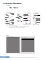
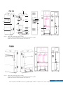
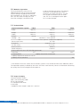
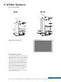
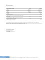
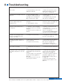
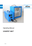
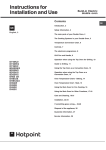
Operating Instructions
en/us
Operating Instructions SPS 07-2007
www.zubler.de
1
Contents
0. Introduction
0.1 Declaration of Conformity
Page
3
1. Suction Machines
1.1 Design
1.2 Method of operation:
1.3 Technical Data:
1.4 Scope of Supply
Page
4
2. Filter Systems
2.1 Technical Design
2.2 Method of Operation
2.3 Technical Data:
2.4 Scope of Supply
Page
7
3. Putting the Suction Machine into Operation
3.1 Connecting Up the Suction Machine
3.2 Switching On the Suction Machine
Page
9
Page 10
4. Functional Description and Adjustment
4.1 Filter Material
4.2 Dedusting System
4.3 Maximum Mode for Laboratory Cleaning and Pipework Maintenance
4.4 Open-loop and Closed-loop Control System
4.5 Changing the Settings of the Extraction System
4.5.1 Changing the Rate of Suction
4.5.2 Changing the Holding Time for Maximum
5. Operation of the Automatic Suction Unit Opener
5.1 Suction Unit Valve
5.2 Automatic Switch AP500
5.2.1 Connection
5.2.2 Setting the Level of Sensitivity
5.2.3 Setting the Run-on Time
5.2.4 Loading Factory Settings (Reset)
Page
12
6. Dust Sockets
Page
16
7. Maintenance of the Central Extraction System
7.1 Emptying the Dust Container
7.2 Emptying the Sand Separator S1
7.3 Emptying the Sand Separator S1
7.4 Changing the Dust Filter Cartridge
7.5 Maintenance on the Main Piping System
7.6 Maintenance Chart for the Central Extraction System
Page
16
8. Troubleshooting
Page
21
9. Spare Parts
Page
22
Page
22
10. Service and Maintenance by the Manufacturer
Page 2
Zubler Gerätebau GmbH ■ Buchbrunnenweg 26 ■ D-89081 Ulm ■ Fon +49(0)731-14 52 -0 Fax +49(0)731-14 52 13
0. Introduction
Dear Customer,
We are pleased that you have decided in
favour of a Zubler central extraction
system and do hope you enjoy using it.
Ongoing development of our technology
is based on collaboration with experienced
dental technicians. The focus is on our aim
to make extraction equipment quieter and
more user-friendly. Excellent performance
and cost-effectiveness are essential.
To ensure smooth operation you should
read the operating instructions carefully.
This extraction system is solely
designed for dry dust.
These operating instructions do not
include a detailed description of
installation. It is assumed that the
extraction system has already been
installed in your laboratory by the
technical staff and that the suction
units have been connected up.
No liability claims will be accepted on
the basis of the illustrations or technical
information. We reserve the right to
make modifications, without updating
these instructions.
0.1 Declaration of Conformity
We, Zubler Gerätebau GmbH
Buchbrunnenweg 26
89081 Ulm Jungingen
declare that the product, central dust extraction
system
complies with the protection requirements
of the following directives:
89/336/EEC
EMC Directive
73/23/EEC
Low - voltage Directive
93/68/EEC
CE Marking
89/392/EEC
Machinery Directive
This declaration becomes invalid if there is
any modification to the product which is not
agreed with us.
Kurt Zubler
Managing Director
Page
Zubler Gerätebau GmbH ■ Buchbrunnenweg 26 ■ D-89081 Ulm ■ Fon +49(0)731-14 52 -0 Fax +49(0)731-14 52 13
3
1.
Suction Machines
1.1. Design
6
8.2
8.1
8
27
7
28
29
26
33
5
37
3
9
4
25
24
31
23
10
2
30
13
Fig. 1: Left: Front view of FZ5/2
Centre: Internal components of the FZ5/2 extraction system
Right: Left view of FZ5/2 without side cover (4)
Legend
2 380V / 16A socket
23 Star grip nut
3 Compressed-air nozzle
24 Filter cartridge
4 Side cover
25 Filter dedusting system
5 ON/OFF master switch
26 Blower
6 Cooling air port for motor
27 Motor
7 Motor housing
28 Access to motor and cable terminal
8 Button for maximum suction
29 Air outlet (left)
8.1 Dust box control/Reset button
30 Housing for electronic control
8.2 Malfunktion control/Reset button
31 Intake port (left)
9 Filter housing
36
38
39
34
12
11
14
35
33 Frequency inverter
10 Dust socket
34 Compressed-air cylinder
11 Lever
35 Compressed-air hose for filter dedusting
12 Dust container
36 Filter dedusting valve
13 Base plate
37 EASY control relay
14 Vacuum hose for dirt container
38 Safety valve
15 Dirt pan cover
39 Pressure-reducing valve
22 Dirt pan
Page 4
Zubler Gerätebau GmbH ■ Buchbrunnenweg 26 ■ D-89081 Ulm ■ Fon +49(0)731-14 52 -0 Fax +49(0)731-14 52 13
6
8.2
8.1
8
7
29
33
5
9
37
31
3
4
10
3
15
2
30
14
22
12
11
13
Fig. 2: Left: Front and rear view of FZ10
Centre: Internal components of the FZ10 extraction system
Right: Left view of FZ10 without side cover (4)
Fig. 3: Left: Front and rear view of FZ20
Centre: Internal components of the FZ20 extraction system
Right: Left view of FZ20 without side cover (4)
Page
Zubler Gerätebau GmbH ■ Buchbrunnenweg 26 ■ D-89081 Ulm ■ Fon +49(0)731-14 52 -0 Fax +49(0)731-14 52 13
5
1.2. Method of operation:
The dust produced at source in the
laboratory passes into the central extraction
system through the piping connected to
the intake port (31). The dust is separated
off in the dust filter cartridge (24). The
dust filter cartridge is attached to the
inside of the filter housing (9). The filtered
air passes via the blower (26), which is
located in the motor housing (7), into the
exit air pipe connected to the air outlet
(29). The air is discharged into the open
air via a noise damper.
1.3. Technical Data:
Type of extraction system:
FZ5/2
FZ10
Width
760 mm
720 mm
Height
1620 mm
2100 mm
Depth
600 mm
590 mm
Weight
165 kg
200 kg
Voltage
EU
380-480 V ± 10% 3-phase
US
200-230V ± 10% 3-phase (single phase optional)
Power input (max.)
9.2 kVA
Frequency
50-60 Hz ± 2 Hz
Air flow (max.)
27 m2/min
Vacuum (max.)
8000 Pa
Motor frequency
0-100 Hz
Filter quality*Dust class "M" (DIN EN 60335-2-69)
Filter area
5m2
10m2
Compressed-air
supply5- 8 bar oil and water-free
Capacity of pressure vessel 10l 14l 14l
Capacity of dust container
FZ20
1100 mm
2100 mm
600 mm
230 kg
20m2
40l
* The filtered air from the central dust extraction systems must not be returned to the laboratory rooms.
The separation capacity indicated by dust class "M" of the main filter only serves as information concerning
the quality of exit air discharged into the open air.
1.4. Scope of Supply:
Central extraction system
380V / 16A connecting cable
Exit air noise damper
5 m compressed-air hose
5 dust bags
1 telephony noise damper 1,000 mm x 200 mm
Page 6
Zubler Gerätebau GmbH ■ Buchbrunnenweg 26 ■ D-89081 Ulm ■ Fon +49(0)731-14 52 -0 Fax +49(0)731-14 52 13
2.
Filter Systems
2.1. Technical Design
68
69
68
69
9
9
4
10
10
4
11
12
11
12
13
Fig. 4: Left: Filter system EF5
Right: Filter system EF10
13
4
9
10
11
12
13
15
68
69
Side cover
Filter housing
Dust socket
Lever
Dust container
Base plate
Dirt pan cover
Extraction nozzle
Cover
2.2. Method of Operation
Some of the laboratory work spaces are
connected to this filter unit via a separate
piping system. A connection is made to
the suction machine via extraction nozzle
68. Owing to this so-called dual-circuit
system it is possible to segregate types
of dust. The EF 5 filter systems can be
used either for pure dirt or for mixtures
of dust containing precious metals. The
aim is to reduce separation costs by
disposing of the main bulk of laboratory
dirt directly and ensuring that dust
containing precious metals has a higher
level of concentration.
Page
Zubler Gerätebau GmbH ■ Buchbrunnenweg 26 ■ D-89081 Ulm ■ Fon +49(0)731-14 52 -0 Fax +49(0)731-14 52 13
7
2.3.Technical Data:
Type of filter system
Width
Height
Depth
Weight
Voltage
Power input (max.)
Filter quality*Dust class "M" (DIN EN 60335-2-69)
Filter area
Compressed-air supply5- 8 bar oil and water-free
Capacity of pressure vessel
Capacity of dust container
EF5
760 mm
1220 mm
600 mm
110 kg
EF10
720 mm
1620 mm
600 mm
120 kg
24V
10 W
5m2
10m2
10l
14l
40l
* The filtered air from the central dust extraction systems must not be returned to the laboratory
rooms.put The separation capacity indicated by dust class "M" of the main filter only serves as information
concerning the quality of exit air discharged into the open air.
2.4. Scope of Supply:
Filter system EF10
5 m compressed-air hose
5 dust bags
Page 8
Zubler Gerätebau GmbH ■ Buchbrunnenweg 26 ■ D-89081 Ulm ■ Fon +49(0)731-14 52 -0 Fax +49(0)731-14 52 13
3.
Operation
Important: The seal (sealing lip) of the
dust filter cartridge is compressed
the first time it is screwed tight. On
account of "settling" the pressure
exerted decreases after a few days.
Therefore, 4 weeks after putting into
operation or changing the filter check
the star grip nut (see section 7.4 on
page 19) to make sure it is firmly in
place, and tighten up if necessary.
3.1 Connecting Up the Suction Machine
Installation of the machine and connection
to the piping system are normally performed
by specialised fitters when the extraction
system is installed. Connect the extraction
pipes coming from the laboratory to the
intake nozzles, item 31 (on the left and
right). Connect the exit air piping system
to the nozzle, item 29. Use the flexible
380 V, 16A connecting cable enclosed in
order to make the electrical connections
between the extraction system and your
building power supply. Plug the coupling
with plug (2) on the extraction side and
the cable connector into the socket of
the 380V building power supply.
Press the connection nipple (18) with the
compressed-air hose (17) into the couling
17
18
19
20
(20) of the compressed air network (21)
(5-8 bar). When disconnecting, hold the
connection nipple tightly and retract the
locking mechanism (19) in the direction
of the arrow.
The system must not be operated without
being connected to the compressed air
supply or else the dust filter cartridge
cannot be subjected to automatic
compressed-air dedusting.
To prevent the filter cartridge from
becoming clogged, the compressed air
from your compressed air system must
be oil and water-free. Modern cold air
dryers meet the requirements for
industrial compressed air in accordance
with ISO 8573.1
21
17
18
19
20
21
3.2 Switching On the Suction Machine
Put the Central Extraction System into
operation by turning on at the ON/OFF
power switch (5). Beforehand check to
make sure there is a supply of compressed
air in the extraction system and in the
laboratory. If the compressor system is
only started up at the same time as the
suction machine, the suction units in the
laboratory will be open because the
network is not pressurised. In addition,
make sure the dust container is positioned
correctly and the lever (11) is in a vertical
position. Only then is the extraction
system sealed tight. Before switching on,
please also check to make sure the vacuum
hose (14) is firmly inside the push-fit
coupling of the dust container (12).
Compressed-air hose
Connection nipple
Locking mechanism
Quick-release coupling
Compressed-air network
Filter dedusting start-up delay:
After switching on the extraction system
it takes approx. 5 min for the suction
motor to start up. The purpose of the
time delay is to ensure efficient filter
dedusting without any suction being
applied. During the first few minutes
before dedusting it also ensures that the
laboratory compressor can build up the
required air pressure. After three
dedusting surges the motor starts up and
the extraction system is ready
Note:
This function is not available on all
machines. Particular suction systems
e.g. for schools and universities,
with smaller dust accumulation, are
equipped with different control
systems.
Zubler Gerätebau GmbH ■ Buchbrunnenweg 26 ■ D-89081 Ulm ■ Fon +49(0)731-14 52 -0 Fax +49(0)731-14 52 13
Page
9
4.
Functional Description and
Adjustment of the Suction Machine
4.1 Filter Material
The extraction systems are fitted with
cartridge filters. The filter material used is
certified for dust class M. The permeability
for dust class "M" as per DIN EN 603352-69 is less than 0.1%. A filter certificate
is available on request. The filter material
used is registered under test certificate
no.: 9101201/6210.
4.2 Dedusting System
To prevent the pores of the dust filter
cartridge (24) from becoming clogged
there is a dedusting system (25) (rotary
air nozzle) inside the dust filter cartridge.
The filter surface is automatically subjected
to compressed air by the rotating
dedusting system at fixed intervals. The
interval is set to 10 minutes by default
but it can be changed by our Customer
Service on the timer (37). The timer
actuates the valve (36). A compressed-air
cylinder (34) is necessary for the filter
dedusting system. The compressed-air
cylinder is fitted with a pressure-reducing
valve (39), which restricts laboratory
compressed air to 3 bar, and a safety
valve (38) (set to 3.5 bar).
4.3 Maximum Mode for Laboratory Cleaning and Pipework Maintenance
4
8
8.1
8.2
You can switch off the automatic control
system by pressing the Maximum button
(8) for maintenance work, which is located on the front of your extraction
system and can also be connected to
your laboratory rooms on request. Then
the blower runs up to maximum speed,
and hence maximum suction, for a fixed
period of time (the default is 15 minutes).
If you press the Maximum button again,
the system resumes automatic control
mode. Maximum suction is required
when cleaning laboratory rooms or the
main pipes. For maintenance work
(cleaning the main pipes) read more in
section 7.5 on page 25.
Abb. 10: Maximum Taster
4 side cover
8 Button for max. suction power
8.1 Button for dust box reset
8.2 Button for malfunction reset
Only dry dust may be extracted. Any
liquids which get it inside the
extraction system can damage the
dust filter cartridge beyond repair!
Page 10
Zubler Gerätebau GmbH ■ Buchbrunnenweg 26 ■ D-89081 Ulm ■ Fon +49(0)731-14 52 -0 Fax +49(0)731-14 52 13
4.4 Open-loop and Closed-loop
Control System
The Central extraction system is equipped
with automatic electronic control. The
frequency inverter (33) is actuated via the
control board (41) with the vacuum sensor
accommodated in the electronics housing
(30). The frequency inverter generates a
rotating field with a variable frequency for
infinite motor (27) speed adjustment at
the blower (26). Since the vacuum is
regulated to a constant level, irrespective
of the number of suction units open,
suction at the various work spaces
41 42 43
44
remains constant. Motor speed, and
hence the suction capacity of the extraction
system, is constantly being adjusted to
current demand. On a daily average the
extraction system only runs at a fraction
of its maximum capacity. That ensures a
long service life, low noise levels and
minimal energy costs. The lower threshold
potentiometer (42) and the upper
threshold potentiometer (44) are specially
set by our fitters for your laboratory using
an air flow meter when the system is
being installed. This basic setting must
not be changed.
45
30
30 Housing for electronic control
41 Control board
42 Lower control threshold potentiometer (black)
43 Control setpoint potentiometer
(suction, red))
44 Upper control threshold potentiometer (black)
45 Microswitch
Fig. 11: Housing with control board
4.5 Changing the Settings of the
Extraction System
1. Turn OFF at the power switch (5).
2. Remove the mains coupling from
plug (2).
3. Unscrew the cover from the
electronic control housing (30).
4.5.1 Changing the Rate of Suction
The rate of suction can be increased by
turning the red potentiometer (43)
clockwise.
Only make slight changes. If the rate of
suction of the extraction system has
declined considerably, it is not normally
due to the setting. Clean the pipes or
change the filter. Consult our service
technicians.
4.5.2 Changing the Holding Time for
Maximum
In the preset (15 min) the first switch is
in the ON position (top). Every switch
which is in the ON position extends
holding time by 15 minutes.
Example: 3 switches in the ON position
results in a period of 3 x 15 minutes = 45
minutes.
Page
Zubler Gerätebau GmbH ■ Buchbrunnenweg 26 ■ D-89081 Ulm ■ Fon +49(0)731-14 52 -0 Fax +49(0)731-14 52 13
11
5. Automatic Suction Unit Opener
5. Operation of the Automatic Suction Unit Opener at the Work Space
51
50
52
47
70
48
40
The automatic switch is54responsible for
detecting an actuated grinder handpiece
and opening the suction unit. If the knee
starter (52) is actuated, the control unit
(51) rotates and admits more current.46
This is detected by the automatic switch,
which opens the suction unit valve (46)
by operating the switching valve (48). If
the grinder handpiece
is switched off, the
55
suction unit remains open for about
another 3 seconds (run-on time) in order
to draw in any residual dust. If you are
working without a grinder handpiece, the
extraction system can be switched on at
an external switch (53) (optional), which
can be fitted underneath the bench top
within reach.
Fig. 12: Diagram of the extraction system
at a work space
46
47
48
49
50
51
52
53
Suction unit valve
Automatic switch
Solenoid valve
Compressed-air supply
Extraction funnel
Grinder handpiece
Knee starter
External button for continuous
extraction (optional)
54 Power cable
55 Piping system
(direction of extraction)
5.1 Suction Unit Valve
57
The suction unit valve (46) is a hose pinch
valve with a rubber diaphragm. The latter
is subjected to compressed air (inflated)
when the valve is closed. To open the
suction pipe, the compressed air is shut
off and the valve is bled. The rubber
diaphragm relaxes to form a circular
cross-section.
58
56
To change the suction unit valve please
read section 7.3 on page 18.
59
60
59
56
57
58
59
60
Connector
Sleeve
Compressed-air hose
Hose nozzles
Valve body
Fig. 13: Suction unit valve
Page 12
Zubler Gerätebau GmbH ■ Buchbrunnenweg 26 ■ D-89081 Ulm ■ Fon +49(0)731-14 52 -0 Fax +49(0)731-14 52 13
5.2 Automatic Switch AP500
Fig. 15: Rear of automatic switch
Fig. 14: Front of automatic switch
72
71
5.2.1 Front Connections
74the valve in the suction hose
73
1. Connect
to the small swivelling 6 mm connector
on the AP 500.
71 Socket for handpiece controller unit
72 Socket for input modul
73 Socket for direct connection
(handpiece controller unit)
76
75
77
74 Socket for switching cable Manual
ON/OF
75 Valve control socket 6mm
76 Elektromagnetic valve
77 Compressed air 1 bar Socket 8mm
78 Network socket (only for FZ2)
79 Mains input
80 Fuse
79
80
81
81 Silencer (pneumatic)
78
2. Check the compressed-air supply,
which must be reduced to 1 bar for
connecting the suction unit opener. For
this purpose use the preset pressurereducing valve from Zubler, DM01,
ordering code 825/297.
3. Connect the compressed-air supply
(8 mm connector) on the AP500 to
your laboratory compressed-air supply
via the pressure-reducing valve. Before
doing so, check to make sure there is
an 8 mm blind plug on one side of the
connector on the module, or proceed
by connecting to the next module.
4. Plug the AP500 into a socket using the
power cable enclosed.
5. Insert the mains plug of your grinding
system into the socket on the AP 500
control module.
6. (Optional) Connect the additional
switching cables (see section
"Accessories").
Fit the AP500 switch module under
the bench near to your grinder handpiece controller in such a way that
you can operate the input module
from an accessible position. The
input module is necessary for
matching to your grinder once and
for setting the desired run-on time
(see page 14 onwards). If you
change the grinding system or the
knee/foot controls for your handpiece,
you will have to readjust.
Page
Zubler Gerätebau GmbH ■ Buchbrunnenweg 26 ■ D-89081 Ulm ■ Fon +49(0)731-14 52 -0 Fax +49(0)731-14 52 13
13
5.2.2 Setting the Level of Sensitivity
Load defaults
How to load the basic settings for a list
of the most common machines. (run-on
time always 3 seconds)
Code 61
Schick C2, C3, KaVo K11 ,
K10 (delivered))
Code 62
KaVo K-Control(1) , K9, K4
Code 63
NSK Ultimate 400,
88
KaVo, SF
Code 64
Schick CN
Code 65
NSK Ultimate 500(2),
K9(3), K4(3)
89
Example: For KaVo K-Control press as fol
lows:
C
6
2
●
●
1 The setting for Kavo K-Control is irrespective of the
handpiece being used.
2 Switch the device to "Extraction mode" beforehand (see
Operating Instructions)
3 Alternative setting with higher sensitivity than Code 62.
90
Fig. 16: Input modul
88 LCD-display
89 Code-input
90 Enter
Calibrate automatically
The control unit measures, calculates and
stores the optimum response threshold
for your device on its own. Use this input
option for all unlisted devices, or in addition
Step1: Switch ON grinder control unit
(handpiece not running) Step2 Press:
after entering Codes 61- 65.
C
2
●
●
Step3 Now run the handpiece at the low
speed at which you want the extraction
system to cut in. Step4: Press (while the
handpiece is run ning):
C
3
●
●
Page 14
Zubler Gerätebau GmbH ■ Buchbrunnenweg 26 ■ D-89081 Ulm ■ Fon +49(0)731-14 52 -0 Fax +49(0)731-14 52 13
5.2.3 Change run-on time
This makes it possible to enter the run-on
time in seconds (von 0-250), at which
you want the suction unit to remain open
in order to extract residual dust after the
grinder handpiece has come to a halt.
The default setting is 3 seconds. An
extension of run-on time may be useful
to bridge short grinding pauses or change
tools, as required by the user.
To change the run-on time press:
C
7
●
0000 c
Now enter the desired run-on time in
seconds and confirm the entry by pressing the dot.
(example: 12 seconds)
1
2
●
0012 c
After entry the display shows:
---5.2.4 Loading Factory Settings
Lost basic settings can be restored by
entering Code 60. Press:
C
6
0
●
●
Then perform the sensitivity setting for
your handpiece controller again by
selecting Codes 61 to 65 or performing
automatic calibration.
Page
Zubler Gerätebau GmbH ■ Buchbrunnenweg 26 ■ D-89081 Ulm ■ Fon +49(0)731-14 52 -0 Fax +49(0)731-14 52 13
15
Dust Socket
6.
67
66
Fig. 17: Dust socket
7.
66 Dust socket
67 Flap
Dust sockets are additional suction units
with a flap which can be opened manually
– they are positioned at appropriate
points throughout the laboratory to make
it possible to clean the workbenches and
floor. A special flexible extraction hose
can be plugged into the dust socket (66).
To achieve a higher level of extraction,
press the Maximum button in the laboratory (see section 4.3 on page 10)
Maintenance of the Central
Extraction System
7.1 Emptying the Dust Container
The dust container has to be emptied
regularly. When the system is new it is
essential to check the level in the dust
container once a week. If you discover
that the container is 3/4 full and you
ought to empty the dust container, enter
the emptying frequency on the maintenance chart for central extraction systems
on page 26.
The sucction system has an additional
control button (8.1) to show “dust box
full”. This button light´s up after a certain
time. You can chance this operating
hours counter for you personal requirements (see extra manual).
1.Before emptying the dust container (12)
turn OFF the power switch (5) and
allow the suction turbine to come to a
halt.
2. Remove the vacuum hose (14) from
the dust container (12).
3. Pull the lever (11) on the right-hand
side of the dust container towards you
and remove the dust container with
the dust bag inside it.
4. Close the dust bag and dispose of it
according to local regulations.
5. Place a new dust bag in the dust
container and pull the opening of the
bag over the top edge of the dust
container.
6. Insert the dust container up to the
stop and make sure the dust container
is centred in relation to the seal.
7. Move the lever to the vertical position.
8. Insert the vacuum hose on the dust
container (dust box).
9.Turn ON the power switch (5) and
press the control button (8.1).
Page 16
Zubler Gerätebau GmbH ■ Buchbrunnenweg 26 ■ D-89081 Ulm ■ Fon +49(0)731-14 52 -0 Fax +49(0)731-14 52 13
7.2 Emptying the Sand Separator S1
The sand separator protects the piping
system against abrasion due to sandblasting. If no sand separator is installed
downstream of a sandblaster or if the
sand separator is not emptied regularly,
the silica sand will erode through the
pipe walls in the course of time.
82
83
84
85
82
83
84
85
86
87
Cover with baffle
Connecting port
Housing
Sight glass
Flap with catch
Floor for sand container (sand container capacity = 10 litres)
86
87
If sand is visible in the sight glass (85),
the sand separator has to be emptied. If
a new sand separator has been installed,
you should check the level at short intervals at the beginning. Later on, define an
emptying frequency, which you can enter
on the maintenance chart on page 26.
Fig. 18: Sand separator S1
1. Turn OFF the extraction system at the
power switch (5) and allow the suction
turbine to come to a halt.
2. Place the sand container on the floor
(87).
3. Open the flap (86) by pulling the catch
to the right (sand flows out)
4. When the container is completely
empty, press the flap upwards firmly
until the catch snaps into place.
5. Remove the container and dispose of
the sand according to local regulations.
It is essential to empty the sand
container regularly depending on
how much dust has accumulated!
Page
Zubler Gerätebau GmbH ■ Buchbrunnenweg 26 ■ D-89081 Ulm ■ Fon +49(0)731-14 52 -0 Fax +49(0)731-14 52 13
17
7.3 Changing the Suction Unit Valve
The rubber diaphragm of the suction unit
valve is a wearing part. A defect becomes
apparent as follows:
- A slight noise can always be heard
when the suction unit is closed.
Compressed air emerges from the
defective diaphragm to the interior of the
suction hose. After a lengthy period of
time, the valve will no longer close
completely and the suction unit is also
constantly performing suction.
Fig. 19: Automatic suction unit valve
After changing, please return the
defective part so that the rubber
diaphragm can be replaced.
Procedure for changing the suction
unit valve
1. Turn OFF the extraction system at the
power switch (5).
2. Disconnect the compressed-air supply
for the bench group concerned from
the compressor network
If a defect is found, the valve must be
changed as soon as possible. If a laboratory
is being fitted with a new system, you
will receive a suction unit valve as a
spare part.
3. Press the sleeve (57) of the connector
(56) up to the connector and at the
same time withdraw the compressedair hose (58).
4. Remove extraction hoses from the
connection nozzles (59) or withdraw
the valve from the pipe branch.
5. Insert a new valve and reconnect the
hoses.
6. Insert the compressed-air hose into
the connector and push it firmly away
from you until it snaps into place.
7. Turn ON the extraction system and
reconnect the compressed-air supply.
Experienced staff can change a valve
while extraction is running. The
pressure is set to 1.0 bar during installation. Pressure-reducing valves are
set at the factory. The pressure at the
suction unit valve should be at least
1 bar but must not exceed 1.2 bar.
Page 18
Zubler Gerätebau GmbH ■ Buchbrunnenweg 26 ■ D-89081 Ulm ■ Fon +49(0)731-14 52 -0 Fax +49(0)731-14 52 13
7.4 Changing the Dust Filter Cartridge
The dust filter cartridge has to be
changed from time to time. The frequency
of changing depends on the type and
quantity of dust (1 to 4 years). Moist dust
and sticky dust tend to reduce the service
life of the dust filter cartridge. The filter
cartridge should always be changed by a
service technician. If the filter cartridge is
not changed properly, it is the laboratory
which is liable for any consequential
damage.
Before changing the dust filter cartridge it
is essential to observe the following
instructions.
Before changing the filter cartridge
always perform a maintenance
procedure (section 7.5) so that the
new cartridge is not immediately
soiled by dust still in the piping system!
(Empty the containers before performing maintenance!)
For your own safety, only perform
filter changes if you are wearing
suitable safety equipment (gloves,
respirator).
Always store and dispose of
contaminated filters in a container
with a dustproof seal immediately
after removal (plastic bag).
Proceed as described below
■ Turn off the system at the power
switch and allow the blower to come
to a halt.
ü
■ Only applicable to FZ10 and FZ20:
remove the pan cover and shake off
accumulations of dust by tapping the
filter housing and pan.
■ Remove the vacuum hose from the
container, lower the lever and remove
the container.
■ Only applicable to FZ10 and FZ20:
withdraw the pan.
ü
Abb. 20
■ Undo and remove the star grip.
Caution: the filter cartridge also
becomes detached!
■ Remove the filter cartridge from
below and dispose of it immediately in
a plastic bag with a dustproof seal in
accordance with the normal legal
regulations in your country.
Important !
■ Now insert the new filter cartridge.
When doing so, make sure the
cartridge is not tilted.
If a filter cartridge is not inserted
properly, this will cause soiling to the
dedusting system and motor,
damaging them beyond repair!
■ Before tightening the star grip, check
to make sure that the filter cartridge
has been inserted properly – it should
be possible to rotate it easily in the
uppermost position, with the threaded
rod projecting at the bottom by
approx. 25-30 mm.
Page
Zubler Gerätebau GmbH ■ Buchbrunnenweg 26 ■ D-89081 Ulm ■ Fon +49(0)731-14 52 -0 Fax +49(0)731-14 52 13
19
7.5 Maintenance on the Main Piping System
Since the flow velocities in the main
pipes in closed loop control are lower
than at the suction units, dust may be
deposited in those pipe sections. If
maintenance is not performed regularly,
deposits can accumulate and thus cause
constrictions in the piping system.
Inspection
work is necessary at maximum intervals
of approx. 2-3 months, or at shorter
intervals if suction declines in any area of
the laboratory.
1. Empty the dust container prior to
performing maintenance work! 2.
Press the Maximum button on the
extraction system or in your laboratory
(optional).
3. All extraction ports must be closed
during maintenance work.
4. Open each maintenance port for 2
minutes, one after the other. Only one
maintenance port may be open at a
time.
6. When maintenance has been completed
and all the ports have been closed
again, press the Maximum button for
maintenance again and the system
resumes closed- loop control.
7. Empty the dust container again after
performing maintenance.
7.6 Maintenance Chart for the Central
Extraction System
On the reverse site of this manual yo find
a model layout of a maintenance chart for
copy. Please use this model or another
chart /calendar for documentation of the
done checks that were carried out. You
should organize the regular
maintenances with the dental technicians
in the laboratory or with the help of a
janitor.
7.7 Service and maintenance by the
manufacturer
The suction system is serviced by our
Service Department upon request.
The maintenance works include:
We gladly provide you with a quote for a
maintenance contract.
■ Revision of the main lines
If necessary, adjustments are made and
parts will be replaced.
■ Verify the tightness of hose and pipe
system
■ Remedy of sand blasting damages
■ Empty dust containers of central suction,
sand and precious metal separators
■ Check vacuum and vacuum regulation
■ Check motor and blower
■ Check filter condition and filter
cleaning system
■ Review vacuum power and automatic
operation on all workstations
■ Verify pressure and tightness on all
port openers
Page 20
Zubler Gerätebau GmbH ■ Buchbrunnenweg 26 ■ D-89081 Ulm ■ Fon +49(0)731-14 52 -0 Fax +49(0)731-14 52 13
8. Troubleshooting
Fault
Cause
Remedy
No suction
1. Dust container is not in the
uppermost position
1. Move dust container to the
uppermost position with lever
(11) (see 1.1. on page 4)
Unfiltered dust escapes into the
open air
1. Filter cartridge is loose
2. There is a crack in the filter
cartridge or the cartridge has
been inserted at an angle
1. Tighten the star grip (23) (see
1.2.3 on page 7)
2. Change the filter cartridge
(24) (see 7.4 on page 24)
System only runs in the upper
control range or does not
regulate at all
1. Filter is blocked owing to
moisture
2. Control board is faulty
1. Check filter and change if
necessary (see 7.4 on page 19)
2. Call Customer Service
Rate of suction declines or is
inadequate
1. Deposits in the main pipes
2. Dust container has not been
emptied
3. Rate of suction has been set
too low
1. Perform maintenance (see
7.5 on page 20)
2. Empty the dust container (12)
(see 7.1 on page 16)
3. Turn the control potentiometer
(43) clockwise (see 4.4 on page 11)
Suction unit no longer closes
and air is escaping from the
suction unit valve
1. Suction unit valve faulty
1. Change the suction unit opener (see 7.3 on page 18)
Suction unit closes and air is
escaping from the suction unit
valve
1. Pressure on suction unit
valve is too high
2. Suction unit valve faulty
1. Check pressure and reduce if
necessary (max. pressure 1.2
bar) (see 7.3 on page 18)
2. Change the suction unit
opener (see 7.3 on page 18) 3)
All suction units open
1. Compressor not switched
ON
1. Switched ON the compressor
Automatic switch with automatic
handpiece detection is not working
1. Mains plug of the machine is
not plugged into the automatic
socket
2. Power cable is not connected
to the non-heating appliance
plug (65)
3. Interface switch is not matched to your machine
1. Insert the mains plug of the
machine into the automatic
sokket (see 5. on page 12)
2. Connect the power cable to
the power supply and nonheating appliance plug (see 5.1
on page 12)
3. Check the setting of the
interface switch (see 5.2.2 on
page 14)
Page
Zubler Gerätebau GmbH ■ Buchbrunnenweg 26 ■ D-89081 Ulm ■ Fon +49(0)731-14 52 -0 Fax +49(0)731-14 52 13
21
9. Spare Parts
Spare parts
Dust filter cartridge dia. 328x300 mm for FZ5 / EF5
Dust filter cartridge dia. 328x600 mm for FZ10 / FZ20
Dust bags (10 bags)
Dust bags (50 bags)
New suction unit valve
Repaired and exchanged suction unit valve
Part number
556/062
556/052
037/253
037/2530
752/065
752/065
Page 22
Zubler Gerätebau GmbH ■ Buchbrunnenweg 26 ■ D-89081 Ulm ■ Fon +49(0)731-14 52 -0 Fax +49(0)731-14 52 13
Seite
Zubler Gerätebau GmbH ■ Buchbrunnenweg 26 ■ D-89081 Ulm ■ Fon +49(0)731-14 52 -0 Fax +49(0)731-14 52 13
23
Copy Maintenance Plan CW____-____
7.6 Maintenance on the Main Piping System
On the central extraction system the dust container must be emptied every _____ weeks.
Date
Signature
Date
Signature
On the sand separator S1 the dust container must be emptied every _____ weeks
Date
Signature
Date
Signature
On filter systems EF5 and EF10 the dust container must be emptied every _____ weeks.
Date
Signature
Date
Signature
The piping system has _____ maintenance ports (see drawing). In the piping system the maintenance
flaps must be opened individually for 2 minutes, one after the other, at intervals of 14 days.
Date
Signature
Date
Signature
Page 24
Zubler Gerätebau GmbH ■ Buchbrunnenweg 26 ■ D-89081 Ulm ■ Fon +49(0)731-14 52 -0 Fax +49(0)731-14 52 13