1
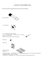
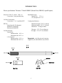
12288 Brawn Side Rd. 22, Wainfleet, Ontario, Canada L0S 1V0 Phone 905-899-3473 e-mail [email protected] Fax 905-899-2262 INSTALLATION / OPERATING INSTRUCTIONS FOR Easy Radiant “Works” HEATWAVE INFRARED RADIANT TUBE HEATER MODEL NUMBERS GH40N GH40P 40,000 BTU LIQUID PROPANE OR NATURAL GAS TECHNICAL DATA FOR VENTED RADIANT TUBE HEATER The installation must comply with local codes and CAN / CGA B – 149 in Canada or the National Fuel Gas codes ANSI Z 83.20 / CSA 2.34 (2008) and ANSI Z83.20A / CSA 2.34 (2010) and CAN/CGA 21.7 .M91 for gas burning appliances. WARNING: Improper installation, adjustment, alteration, service or maintenance can cause property damage, injury or death. Read the installation, operating and maintenance instructions thoroughly before installing or servicing this equipment. AVERTISSEMENT. Une installation, un réglage, une modification, une réparation ou un entretien incorrect peut entraîner des dommages matériels, des blessures ou la mort. Li sez attentivement les instructions d’installation, de fonctionnement et d’entretien avant de procéder à l’installation ou àl’entretien de cet équipement. 1 INSTALLATION, OPERATING AND SERVICE MANUAL FOR EASY RADIANT WORKS “HEATWAVE” MODEL GH40N/GH40P GAS FIRED, VENTED INFRARED TUBE HEATER FOR RESIDENTIAL & COMMERCIAL / INDUSTRIAL APPLICATIONS. FOR YOUR SAFETY Consignes De Securite IF YOU SMELL GAS SI VOUS SENTEZ UNE ODEUR DE GAZ 1. Open windows 1. Ouvrez les fenetres 2. Do not touch electrical switches, or telephone 2. Ne touchez pas aux interrupteurs electriques 3. Extinguish any open flame 3. Eteignez toute flamme nue 4. Immediately call your fuel supplier 4. Contactez immediatement compagnie de gaz 5. If your gas supplier is not available, call the fire department 6. Do not attempt to light this or any other applicance 5. Si votre fournisseur de gaz n’est pas disponible, appeler les pompiers. 6. Ne pas tenter d’allumer ceci ou aucun autre appareil. This appliance has been tested and approved in accordance with ANSI Z 83.20 / CSA 2.34 (2008) and ANSI Z83.20A / CSA 2.34 (2010) and CAN/CGA 21.7 .M91 For Indoor Installation only. Not for use in residential dwellings Installation a l’interieur seulement. Ne pas installer dans un logement. INSTALLER Please take time to read this manual completely to fully understand the instructions prior to the installation. This manual must be left with the owner for future reference. OWNER Retain this manual in a safe place to provide your serviceman information if it becomes necessary. 2 WARNING Improper installation, adjustment, alteration, service or maintenance of this appliance will result in property damage, serious personal injury or death. This appliance must only be installed by a qualified, licensed and experienced gas fitter, familiar with the installation of this type of appliance. For your safety, do not use or store gasoline or other flammable vapours and liquids in the vicinity of this or any other appliance. The installation of this appliance must in all cases conform with local and national building codes or in the absence of local codes with the current CAN/CGA B149.1&2 in Canada or ANSI Z233.1 latest revision in the United States. This appliance has been tested and certified for use in Canada and the United States. Read This Manual Installer This appliance is manufactured by: Read this manual carefully before installing or servicing this equipment. Improper installation, servicing or maintenance will cause death, injury or property damage. Check the minimum distance to combustibles, as noted on the rating plate on the burner and on the following pages of this manual to ensure that the product is suitable for the application. After the installation is complete, check product operation as provided in these instructions, and ensure that a proper installation inspection, as is required in your area, is completed. Easy Radiant Works 12288 Brawn Side Road 22 Wainfleet, Ontario, Canada L0S 1V0 Phone 905 899 3473 Fax 905 899 2262 www.easyradiantworks.com [email protected] 3 CONTENTS OF THE SHIPPING BOX Please check the carton and locate the items shown on this page. Heater Assembly Vent termination 5" (12.7 cm) Balanced flue consisting of 1 - 5" (12.7 cm) vent pipe - 60 inches (or 5 ft) (1.5 meters) long and 1- 3" flue pipe 66 (or 5’6”) (167 cm or 1.6 meters) inches long. Bird Screen Thermostat Protective grill kits (Optional) ALSO INCLUDED . . . NOT SHOWN: ½" (1.2 cm) flexible gas connector, 5 ft. (1.5 meters)( #10 Jack chain for hanging the heater, 2 vent centre guides. OPTIONAL ACCESSORIES: 5 ft. (1.5 meters) vent extension kit, and 90-degree elbow kit. 4 INTRODUCTION Heater specifications “Heatwave” Model GH40N (Natural Gas) GH40P (Liquid Propane) Electrical: 120VAC / 60 Hz / 1-Ph / 1A Connection: 3 pin grounded plug Gas Inlet Connections: Connection: ½" (1.2 cm) Male NPT Manifold Pressure Natural Gas: 3.5" w.c. L.P. (Propane) 10.5" w.c. Venting Specifications: BTU/hr. Natural gas & L.P. (Propane) Minimum 40,000 BTU Maximum 40,000 BTU Gas Inlet Pressure Natural Gas: Minimum inlet 4.0" w.c. Maximum inlet 14.0” w.c. L.P. (Propane) Minimum inlet 11.0" w.c. Maximum inlet 14.0" w.c. Maximum length: 12 ft. (3.6 meters) Minimum length: 2 ft. 6" (.7 meters) Maximum 1 - 90 degree elbow Flue pipe - 3.0" (7.6 cm) diameter Vent pipe - 5.0" (12.7 cm) diameter Important: only flue pipe and vent pipe supplied by the manufacturer may be used. 19.5 m 40.6 cm 24.1 cm 15.2 cm 40.6 cm 22.2 cm 35 cm 5 Where can the heater be installed? Where can’t the heater be installed? Installers responsibility The Heatwave GH40N/GH40P garage heater is intended for use in the following areas: - residential garages - workshops Light commercial / industrial applications such as: - entranceways - storage rooms - lobby areas - manufacturing areas - lunch rooms - agricultural buildings The Heatwave GH40N/GH40P garage heater is not intended for use in residential living spaces or basements. The Heatwave heater, as well as the gas and electrical supply, and the venting of the heater must be installed in accordance with applicable specifications and codes. Only firms (or individuals) well qualified in this type of work should install the system. Consult local Building Inspectors or Fire Marshals for guidance. Use the information given in this manual together with the cited codes and regulations to perform the installation. If any aspects of this installation process are unclear, consult Easy Radiant Works before proceeding. The installer must furnish all materials required that are not furnished with the heater. It is also the installer’s responsibility to see that the materials and installation methods used, result in a job that is workmanlike in appearance and is in compliance with all applicable codes and requirements of this manual. 6 The type of gas appearing on the nameplate must be the type of gas used. Installation must comply with local codes and recommendations of the local gas supplier. If fuel used, does not match the fuel listed on the nameplate, discontinue use immediately and contact Easy Radiant Works for information on converting the appliance to the appropriate fuel. VENTING REQUIREMENTS The Heatwave heater MUST be installed with the venting system supplied with the heater, or one of the optional venting kits available from Easy Radiant Works. DO NOT connect the heater to a separate chimney and DO NOT common vent with any other fuel-burning appliance. The Heatwave heater employs a balanced flue/air venting duct system and must conform to the following minimum and maximum vent requirements. The location, size, installation and termination of vents, as well as the minimum safe distances when penetrating combustible walls, must comply with local codes, national codes and the recommendations of the local gas company. Maximum vent length: 12 feet (3.5 m) plus 1 elbow (elbow available from manufacturer). Minimum vent length: 2 ft. 6 inches (.76 meters) The balanced flue consists of a 3"(7.6 cm) diameter flue that is concentrically positioned inside a 5” (12.7 cm) diameter pipe (see above). The 5" (12.7 cm) diameter pipe supplies outside air that is necessary for combustion, while the 3" diameter flue carries the products of combustion from the heater. The 3” (7.6 cm) and 5” (12.7 cm) pipes are separated by the centering guides supplied with the heater. The balanced flue is applicable for horizontal venting arrangements only. 7 COMMERCIAL/INDUSTRIAL APPLICATIONS Aircraft Hangers The Heatwave heater may be used in certain areas of aircraft hangers. The installation must be in accordance with local and national codes. Heaters in aircraft, storage or service areas must be installed a minimum of 10 ft. (3 meters) above the upper surface of wings or engine enclosures of the highest aircraft that may be housed in the hanger. (This should be measured from the bottom of the heater to the top of the wing, or engine enclosure, whichever is highest from the floor.) In other sections of aircraft hangers, heaters must be installed a minimum of 8 ft. (2.4 meters) above the floor. Heaters installed in aircraft hangers shall be located so as not to be subject to damage by aircraft, cranes or other objects. When installed over hoists, the minimum required safe distances to combustibles must be maintained from the uppermost point of the combustible materials placed on the hoist. Public Garages The Heatwave heater may be used in public garages provided the installation conforms to all local and national codes for the installation of gas burning appliances. Heaters must be installed a minimum of 8 feet (2.4 meters) above the floor. Minimum safe distances to combustibles must be maintained. When installed over hoists the minimum required safe distances to combustibles must be maintained from the uppermost point of the combustible materials placed on the hoist. HAZARDOUS LOCATIONS When there is a possibility of exposure to combustible airborne material or vapour, consult the local Fire Marshal, the Fire Insurance carrier or other authorities for approval of the proposed installation. 8 GENERAL INSTALLATION PROCEDURES CHOOSING A SAFE LOCATION When selecting a suitable mounting location for the heater, it is important to consider the following: The heater must be installed with a minimum of 7 ft. (2.1 meters) between the floor and the bottom of the heater in Canada. In the United States it must be installed with a minimum of 8 ft. (2.4 meters) between the floor and the bottom of the heater, unless the optional protective grill is used, in which case it may be installed with a minimum of 7 ft. (2.1 meters) between the floor and the bottom of the heater. (See grill installation procedure, page 16) The proposed mounting location allows for the minimum required safe distances to combustibles, including vehicles that may be parked in the building, wood, gasoline and flammable objects, liquids and vapours that may be stored in the space. The proposed location will not restrict motion of passageway doors or windows, or the operation of the overhead garage door. The proposed location will provide the best coverage of the total area to be heated. The proposed location will allow the required utilities (i.e. gas, and electric) and venting to be installed (bearing in mind the minimum and maximum vent length requirements). Sufficient clearances will exist to allow for maintenance. Overhead structural members are available, and suitably strong to support the heater assembly. GENERAL GUIDELINES Regardless of the vent arrangements that will be connected to the heater, the following general guidelines for venting must be followed: The 3" (7.6 cm) flue pipe must be centered inside the 5" (12.7 cm) air supply pipe using the centering guides supplied. IMPORTANT: THE FLUE PIPE AND AIR SUPPLY PIPE MUST BE SECURE. IF NOT SECURE, THIS WILL CAUSE DAMAGE TO THE HEATER AND VOID WARRANTY. All horizontal venting sections must slope away from the heater at a rate of 1/4" (6 mm) per foot. The total length of vent pipe (horizontal and vertical) must not exceed 12 ft. (3.6 meters) and must not be less than 2 ft. 6 inches (.7 meters) The vent terminal, mounted outside of the building should not be located above walkways. Condensate produced during operation of the heater could drip onto the walkway and form ice during cold weather resulting in a dangerous condition. Be sure that the venting installation is in accordance with all applicable local codes and recommendations of the local gas supplier. DO NOT connect the heater to a separate chimney, and DO NOT common vent with any other fuelburning appliance. Seal all vent pipe connections with high temperature silicone sealant and secure each connection with three sheet metal screws. 9 GENERAL INSTALLATION PROCEDURES MINIMUM SAFE DISTANCES In all situations, the minimum required clearances to combustibles must be maintained. Combustibles are materials that may catch on fire, and include many common items such as wood, paper, rubber, fabrics, etc. Combustible material such as those noted, and any other combustible materials must not be placed closer to any base or side of the heater that the distances noted on the diagrams on the following page. If you have any questions concerning safe distances to combustibles contact Easy Radiant Works prior to proceeding. It is important to keep the minimum required safe clearances to combustibles at all times to avoid death, personal injury or property damage. Clearances to vehicles parked beneath heaters must be maintained. Signs should be posted to identify any possible violation of the clearances. Maximum allowable stacking height in storage areas should be identified with signs or appropriate markings. The illustrations following identify the minimum required safe clearances to combustibles. 60.9 cm MINIMUM CLEARANCES TO COMBUSTIBLES HORIZONTAL MOUNTING ANGLE MOUNTING 4” 10 cm 4” 10 cm 18” 46 cm Angled back 18” 46 cm 18” 46 cm 4” 10 cm 48” 122 cm 48” 122 cm 10 IMPORTANT The clearance to combustibles “below” (48 inches) (122 cm) indicates the safe clearance to combustibles and NOT the minimum mounting height. CLEARANCES TO COMBUSITBLES The clearance to combustible materials represents the minimum distance that must be maintained between the heater and a nearby surface. The stated clearance to combustibles represents a surface temperature of 90 degree Fahrenheit (32 degrees Celsius) above room temperature. Building material with a low heat tolerance may be subject to degradation of lower temperatures. It is the installer’s responsibility to assure that adjacent material are not subject to degradation. A warning statement that an overhead heater should be installed so that the minimum clearances marked on the heater will be maintained from vehicles parked below the heater. Minimum clearances (inches) from combustibles measured from radiant surface. Clearances are reduced by 1/3, 15 ft (4.6 meters) from the burner. For installation at elevations above 2000 ft (610m), the appliance shall be de-rated 4 percent for each 1000 ft (305m) of elevation above sea level. GAS CONNECTION A qualified and licensed technician must do all gas piping and connections. All gas piping must be done in accordance with all local codes and CAN / CGA B 149 and ANSI standards Z223.1 A 1/8” (.3 cm) NPT plugged tapping accessible for test gauge connection must be supplied immediately upstream of the gas supply connection to the heater. A drip leg must be installed in the gas line at the heater connection. 11 GENERAL INSTALLATION PROCEDURES HEATER ORIENTATION The HeatWave heater may be installed in either of the following orientations: horizontally tilted - 45 degree angle For Horizontal installation (see drawing below): Using “S” hooks; attach four equal lengths of #10 jack chain (or equivalent) to the 4 holes in the front fixed hangers. Connect the 2 free ends of the chain to another “S” hook, as shown. Connect a length of chain from the uppermost “S” hook to the suspension hardware you have previously installed in the ceiling to support the heater. Connect a length of chain to an “S” hook and slip the “S” hook under the center portion of the rear movable hanger. Connect the free end of this chain to the hardware you have previously installed in the ceiling to support the heater. Ensure that the heater is parallel to the floor. For Angled Installation: Adjust the chain lengths at the front fixed hanger to achieve the appropriate angle. Use side suspension point on the rear movable hanger. Horizontal Mounting Angled or tilted Installation 12 TYPICAL INSTALLATION Minimum 6” (15.2 cm) Min. 24” (61 cm) Minimum 7 ft (2.1 meters) Vent terminal Burner Box 16” (40.6 cm) Minimum mounting height 7 ft (2.1 meters) Exterior Wall Movable hangar Floor Minimum mounting height in United States between bottom of tube and floor is 8 ft. (2.4 meters)(7 ft. or 2.1 meters, if optional protective grill is used) VENTING INSTALLATION HORIZONTAL VENTING After the heater has been properly suspended according to this manual, proceed to install the venting as described below: Measure the distance from the floor to the center of the vent collar on the rear of the burner. Transfer this measurement to the inside surface of the exterior wall that the vent will penetrate, and make a mark. Measure the distance between the exterior wall and the vent collar on the rear of the heater. If the distance between the rear surface of the heater and the exterior wall is greater than 5 ft. (1.5 meters), a vent extension kit (available from the manufacturer) is required. For each lineal foot of distance from the heater to the wall, measure down vertically (on the outside wall) 1/4 inch (.6 cm) from the previous reference mark. This new mark is the center of the hole that must be cut to accommodate the 5” (12.7 cm) vent. Cut the hole in the exterior wall. Install the 3” (7.6 cm) flue pipe from the vent collar on the rear of the burner through the exterior wall. The flue pipe must extend a minimum of 6” (15.2 cm) beyond the exterior wall. Install the centering guides over the 3” (7.6 cm) flue. 13 GENERAL INSTALLATION PROCEDURES IMPORTANT: THE FLUE PIPE AND AIR SUPPLY PIPE MUST BE SECURE. IF NOT SECURE, THIS WILL CAUSE DAMAGE TO THE HEATER AND VOID WARRANTY. HORIZONTAL VENTING (CONTINUED) Cut the 3” (7.6 cm) flue pipe to the appropriate length. All joints must be sealed with high temperature silicone adhesive and be secured with 3 sheet metal screws. Assemble and cut if necessary, the 5” (12.7 cm) vent to run between the vent collar on the heater to the exterior wall. All joints must be sealed with high temperature silicone adhesive. From the exterior of the building, slip the 5" (12.7 cm) air supply pipe over the installed 3” (7.6 cm) flue pipe and centering guides. Connect the 5” (12.7 cm) pipe to the vent collar on the heater and seal with silicone adhesive and secure with 3 sheet metal screws. From the exterior of the building, slip the vent terminal onto the 3” (7.6 cm) flue pipe and guide the sleeve portion of the vent terminal into the 5” (12.7 cm) air supply pipe. Secure air vent pipe to the vent terminal with silicone adhesive. Secure the vent terminal to the exterior surface of the wall. VENT ELBOW ASSEMBLY INSTALLING HORIZONTAL VENTING WITH AN ELBOW After the heater has been properly suspended in accordance with this manual, proceed to install the venting and 90-degree elbow as described below. Note: a 90-degree elbow kit (available from the manufacturer) is required for this installation. Measure the distance from the floor to the middle of the vent collar on the rear of the heater, and transfer this measurement to the exterior wall that will be penetrated with the vent. Measure distance “A” and “B” as shown above. If this distance (A plus B) is greater than 5 ft. (1.5 meters), a vent extension kit (available from the manufacturer) is required. 14 GENERAL INSTALLATION PROCEDURES INSTALLING HORIZONTAL VENTING WITH AN ELBOW (CONTINUED) For each linear foot of measured distance (total of A plus B) measure down vertically ¼” (6mm) from the reference mark on the exterior wall. This new reference mark is the centerline of the clearance hole for the 5" (12.7 cm) vent that must be cut in the wall. Proceed to cut the hole in the exterior wall after measuring carefully. Attach the 3" (7.6 cm) elbow portion of the 90-degree elbow kit to the 3" (7.6 cm) flue pipe (length A). Use silicone adhesive and 3 sheet metal screws. Slip the 5" (12.7 cm) air supply pipe over the plain end (without elbow) of the assembled 3" (7.6 cm) flue pipe and elbow. Attach plain end of the 3" (7.6 cm) flue pipe to the rear of the burner box using silicone sealant and 3 sheet metal screws. Attach 5" (12.7 cm) air supply pipe (length A) to the vent collar on the rear of the burner box using silicone sealant and 3 sheet metal screws. Assemble the 90-degree elbow in accordance with the instructions included with the elbow. Secure length “A” of the 5" (12.7 cm) air supply pipe to the elbow assembly using silicone sealant and 3 sheet metal screws. Attach length “B” of the 3" flue pipe to the 3" (7.6 cm) elbow using silicone and sheet metal screws. NOTE: the 3" (7.6 cm) flue pipe must extend a minimum of 6" (15.2 cm) beyond the exterior wall. Cut if necessary to the appropriate length. Install centering guides over the 3” (7.6 cm) flue pipe. From the exterior of the building, slip the 5" (12.7 cm) air supply pipe over the installed 3" (7.6 cm) flue pipe and centering guides. Connect the 5" (12.7 cm) pipe to the 90-degree elbow assembly using silicone adhesive and sheet metal screws. From the exterior of the building, slip the vent terminal onto the 3" flue pipe and guide the sleeve portion of the vent terminal into the 5" air supply pipe that is connected to the rear of the burner box. Secure the air vent pipe to the vent terminal with silicone adhesive. Secure the vent terminal to the exterior of the building. IMPORTANT: THE FLUE PIPE AND AIR SUPPLY PIPE MUST BE SECURE. IF NOT SECURE, THIS WILL CAUSE DAMAGE TO THE HEATER AND VOID WARRANTY. 15 GENERAL INSTALLATION PROCEDURES BIRD SCREEN INSTALLATION The bird screen is supplied in order to prevent blockage of the flue vent by birds or other small animals nesting in the flue. It must be installed directly at the end of the 3” (7.6 cm) flue. orient the bird screen so that the flat surface is toward the exterior. insert the screen into the inside diameter of the 3” (7.6 cm) flue pipe. secure the bird screen with a sheet metal screw. ELBOW ASSEMBLY If you are using the balanced flue elbow, assemble it in accordance with the instructions below. install the spacer. insert the 3” (7.6 cm) elbow into the 5" (12.7 cm) elbow. ELECTRICAL SERVICE INSTALLATION The HeatWave heater requires a grounded 3-prong electrical outlet to be installed within 3 ft. (.9 meters) of the rear surface of the heater’s burner box. Extension cords may not be used. It is recommended that the outlet for the heater be ceiling mounted and should be a dedicated circuit. Heater rating: 120 VAC, 60 Hz, Single Phase, and 1 amp The heater must be electrically grounded in accordance with the following codes: Canada: Refer to Canadian Electrical code, CSA C22.1 Part-1 latest revision. In the United States refer to National Electrical Code, ANSI/NFPA-70- latest revision. THERMOSTAT A 24 VAC thermostat, supplied with the heater, controls the Heatwave. Thermostat wire is not supplied. Purchase 18 - 22 AWG double strand wire for this purpose. Mount the thermostat on an exterior wall whenever possible. Mount the thermostat approximately 5 ft. (1.5 meters) above the floor. Mount the thermostat so that it is not in the direct ray of infra red energy from the heater. Connect one end of the thermostat wire to the 2 terminals on the thermostat. Run the thermostat wire to the thermostat connection on the rear of the burner box. Make sure that the thermostat wire is free of staples or tacks as this can interfere in the operation of the thermostat. GAS SERVICE INSTALLATION A ½ inch (1.2 cm) gas connection is required at the rear of the heater. All gas supply piping must be done by a qualified and licensed professional familiar with the installation of this type of appliance. All gas piping must be in accordance with all local and nation codes on the installation of gas burning appliances. DO NOT ATTEMPT TO RUN GAS LINES YOURSELF. This could result in loss of life, serious injury and/or property damage. 16 GRILL INSTALLATION The protective grill is optional. The protective grill must be used for installations in the United States where the distance from the bottom of the heater to the floor is less than 8 ft. (2.4 meters) If using the protective grill for installations in the United States, the bottom of the heater may be a minimum of 7 ft. (2.1 meters) above the floor. OPERATING SEQUENCE The Easy Radiant gas burner is a very simple device. The normal sequence of events during ignition and operation of the burner is as follows: 1. The heater is energized by means of a thermostat or switch. 2. When 24 volts is applied to the module, the module will energize the blower and close the airswitch. 3. The current flows and energizes the igniter and reaches ignition temperature. No gas flows until the valve is energized and opened. 4. Air pressure generated by the blower will cause the normally open combustion pressure switch to close. The combustion pressure switch is set to allow the normal rate of combustion air to flow into the combustion chamber. Any restriction or blockage will cause the pressure switch to open and shut down the entire system. 5. The current passes through the blocked flue pressure switch, which is normally closed. Any blockage or restriction will cause the pressure switch to open and shut down the entire system. 6. After 17 seconds, the valve is energized and opened. Gas flows through the burner and is ignited. 7. The power is removed from the igniter. The flame sensor is utilized. As long as a flame is present, the valve is held open. If the flame is lost, the control acts to close the valve within one second and a new trial sequence to start up is initiated. 8. If ignition is not achieved, or flame is not sensed, then the control closes, the gas valve, and attempts ignition a second time, and if necessary a third time. If ignition is not achieved after the third try, the control goes into lockout for 30 minutes and power must be interrupted before trying again. At this point it is suggested that an authorized service person be contacted to inspect and test the controls. 9. The heater should continue to function until power is interrupted either by the thermostat being satisfied or manually disconnected. WARNING THIS HEATER MUST BE INSTALLED AND SERVICED BY A TRAINED GAS SERVICE TECHNICIAN ONLY. READ AND UNDERSTAND THESE INSTRUCTIONS THOROUGHLY BEFORE ATTEMPTING TO INSTALL, OPERATE OR SERVICE THE EASY RADIANT WORKS HEATER. FAILURE TO COMPLY WITH THESE WARNINGS AND INSTRUCTIONS, AND THOSE ON THE HEATER COULD 17 RESULT IN PERSONAL INJURY, DEATH, FIRE, ASPHYXIATION, AND / OR PROPERTY DAMAGE. DO NOT STORE OR USE GASOLINE OR OTHER FLAMMABLE VAPOURS AND LIQUIDS IN THE VICINITY OF THIS OR ANY OTHER GAS FIRED APPLIANCE THIS APPLIANCE MAY HAVE SHARP EDGES AND CORNERS, WEAR PROTECTIVE CLOTHING SUCH AS GLOVES AND PROTECTIVE EYE WEAR WHEN SERVICING THIS OR ANY OTHER APPLIANCE. INSTRUCTIONS MUST REMAIN WITH THE UNIT. APPLICATION It is beyond the scope of these instructions to consider all conditions that may be encountered. Installation must conform with all local building codes or, in the absence of local codes, to the National Fuel Gas Code, ANSI Z223.1/NFPA54 in the U.S.A. or the Natural Gas and Propane Installation Code, CSA B149.1 in Canada. The latest edition Electrical Code ANSI/NFPA N0 70 in the U.S.A. and PART 1 CSA C22.1 in Canada must also be observed. Installation of a gas fired tube heater must conform to all heating installation design procedures including clearance to combustibles, connection to the gas and electrical supplies, and ventilation. This heater is not for installation in a Class 1 or Class 2 explosive environment, nor a residence. If installation of this equipment is in question, consult with local authorities having jurisdiction (Fire Marshall, labour department, insurance underwriter, or others). Revisions to codes and/or standards may require revision to equipment and installation procedures. In case of discrepancy, the latest codes, standards, and installation manual will take priority over prior releases. WARNING Where there is the possibility of exposure to combustible airborne materials or vapour, consult the local fire inspector's office, the fire insurance carrier or other applicable authorities for approval of the proposed installation. Do not use in an atmosphere containing halogenated hydrocarbons or other corrosive chemicals. Some compounds in the environment can cause an accelerated rate of corrosion to the heat exchanger. The heater manufacturer cannot anticipate all types and chemical composition of possible contaminants at project sites. Confer with project site safety, health and engineering staff and/or local authorities having jurisdiction such as the Fire Marshall and Department of Labour for possible contaminants and any conflict with the installation of hot surface heating equipment. 18 WARNING HEATER EXPANSION It is normal condition that during heat-up and cool-down a tube heater will expand and contract. Allowances for heater expansion must be made in the gas connection, venting and combustion air ducting. Consider that the heater will expand in length as much as ½ inch (12 mm) or more for every 10 ft (3 m) of system length. Typically, the greater the firing rate, the greater the expansion. WARNING GAS CONNECTION Improper installation, connection, or adjustment can result in property damages, toxic gases, asphyxiation, injury and death. Using an approved flexible gas connector in the USA and Rubber Type 1 hose connector in Canada, the gas supply to the heater must be connected and tested in accordance with all local, state, provincial, and national codes (ANSI Z223.1/NFPA 54 in USA: B149.1 in Canada) and as indicated in the manual. WARNING VENTING Inadequate venting of a heater may result in asphyxiation, carbon monoxide poisoning, injury or death. The heater may be directly or indirectly vented from the space. Venting must be in accordance with all local, state, provincial, and national codes (ANSI Z223.1/NFPA 54 in USA; B149.1 in Canada) and as indicated in this manual. WARNING START-UP SMOKE CONDITION During start up, the heating of material coatings used in the production process of tubes and reflectors will create smoke during the initial period of operation. This condition is normal and temporary. Ensure that there is sufficient ventilation to adequately clear any smoke from the space. Notify site and safety personnel to ensure that alarm systems are not unduly activated. 19 WARNING CLEARANCES TO COMBUSTIBLES A warning statement that an overhead heater should be installed so that the minimum clearances marked on the heater will be maintained from vehicles parked below the heater Location of flammable or explosive objects, liquids or vapours close to the heater may cause fire or explosion and result in property damage, injury or death. Do not use, store or locate flammable or explosive objects, liquids or vapours in proximity of the heater. The clearance to combustible material represents the minimum distance that must be maintained between the outer heater surface and a nearby surface. The stated clearance to combustible represents a surface temperature of 90 degrees F (50 degrees C) above room temperature. It is the installer's responsibility to ensure that building materials with a low heat tolerance, which may degrade at lower temperatures, are protected to prevent degradation. Minimum 24” (61 cm) must be provided at the centre of the appliance for burner servicing. When venting through a wall the vent terminal must be located at least 7.0 ft (2.1m) above grade. This appliance must be mounted at least 7 ft (2.1m) above the floor in Canada, and 8 ft (2.4m) above the floor in the U.S. Minimum clearances (inches and cm) from combustibles measured from radiant surface. The clearances are reduced by 1/3, 15 ft (4.6 meters) from the burner. INSTALLATION IN COMMERCIAL AIRCRAFT HANGARS Low intensity radiant tube heaters are suitable for use in aircraft hangars when installed in accordance with the latest edition of the Standard for Aircraft hangars, ANSI/NFPA No. 409 in the USA, or the Canadian Natural Gas and Propane Installation Code, B149.1 A minimum clearance of 10 ft (3m) above either the highest fuel storage compartment or the highest engine enclosure of the highest aircraft, which may occupy the hangar. The clearance to the bottom of the heater shall be measured from the upper surface of either the fuel storage compartment or the engine enclosure; whichever is higher from the floor. A minimum clearance of 8 ft (2.4m) must be maintained from the bottom of the heater to the floor in other sections of the aircraft hangar, such as offices and shops, which communicate with areas for servicing or storage. For proper mounting clearances, refer to the clearances to combustibles in these installation instructions. Heaters must be located where they are protected from damage to aircraft and other objects, such as cranes and movable scaffolding. Heaters must be located so as to be accessible for servicing and adjustment. 20 INSTALLATION IN COMMERCIAL GARAGES AND PARKING STRUCTURES Low intensity heaters are suitable for use in commercial garages when installed in accordance with the latest edition of the Standard for Parking Structures, ANSI/NFPA 88A, or the Standard for Repair Garages ANSI/NFPA No. 88B, or the Canadian Natural Gas and Propane Installation Code, B149.1 WARNING INSTALLATIONS OTHER THAN SPACE HEATING Use for process or other applications that are not space heating will void the products warranty. Process application requires field inspection and/or certification by local authorities having jurisdiction. IMPORTANT Single or multiple heater placement must be such that continuous operation of heater(s) will not cause combustible material or materials in storage to reach a temperature in excess of ambient temperature plus 90 degrees Fahrenheit (50 degrees Celsius). It is the installer’s responsibility to ensure that building materials with a low heat tolerance, which may degrade at lower temperatures, are protected to prevent degradation. Refer to Clearance to Combustibles information in these installation instructions. GENERAL INSTALLATION PROCEDURE PRE-INSTALLATION SURVEY It is recommended that a full heating design, including a heat loss calculation be conducted. Heater sizing and placement must consider available mounting height, sources of heat loss, and clearances to combustibles with respect to stored material, moveable objects (cranes, vehicles, lifts, overhead doors, etc) sprinkler systems, and other obstructions on the site. Consideration must also be given to vent / duct placement and the allowable combined lengths of vent and duct. 1. Carefully survey the area to be heated and place the burner and combustion chamber in the coldest area if possible. 2. The heater shall be hung in such a fashion so as to conform with the clearances to combustibles described on the name plate. 3. Clearances to combustibles must be maintained from vehicles parked below. 4. Adequate clearances must be maintained for installation in public garages and airplane hangar. 5. It should be located with respect to building construction and equipment, so as to provide sufficient clearances and accessibility for servicing. 6. The installation must comply with local codes and CAN/CGA B-149 in Canada or the National Fuel Gas codes ANSI Z 223.1 in the United States. 21 ELECTRICAL 120V, 60 HZ, 3 AMPS STARTING, 1 AMP RUNNING Ignition System: 120 Volt / Hot surface igniter Thermostat control: Heaters are designed for compatibility with either 120 Volt thermostat controllers or 24 Volt thermostat controllers. For use with 120 Volt controllers, the heater must be plugged into a “switched” 120 Volt duplex receptacle, where the receptacle is switched by the thermostat controller. Heating zones may be established where one 120 Volt thermostat, controls more than one heater, provided the total heater electrical load does not exceed the maximum allowable amperage on the circuit. For 24 volt thermostat control plug the heater into a 120 Volt duplex receptacle. Remove the jumper wire on the control box marked “24 Volt thermostat” and connect the thermostat wire to the terminals. Ensure that if the thermostat has a heat anticipator, that the heat anticipator is set at maximum. When using a 24 Volt thermostat, only one heater may be controlled by one thermostat. 1. Electrical installation must be grounded in accordance with CSA standard C22.1 part 1 in Canada or The National Electrical code ANSI NFPA 70 (latest edition) in the United States. 2. Polarity of line voltage and neutral wires must be maintained. 3. The total load of all heaters in a circuit must be considered not to overload the circuit. NATURAL GAS AND LIQUID PROPANE CONVERSION 1. 2. 3. 4. 5. 6. 7. 8. Turn off gas supply at the appliance service valve. Remove regulator cap screw and pressure regulator adjusting screw Replace the existing spring with replacement spring. Re-install regulator cap screw and pressure regulator adjusting screw. Replace gas orifice with the one provided by the manufacturer. Check the regulator setting using a manometer. Mount the conversion label on the gas control. Mount the new rating label on the heaters. ROUTINE MAINTENANCE For best results and to ensure years of trouble free operation, a qualified service technician should inspect the system before each heating season. A qualified service technician should be contacted for any service that is required, in addition to routine maintenance. Check condition of blower scroll and motor to ensure it is free of dust and dirt. Check the condition of the burner and carefully remove any dust and debris from inside the burner compartment. Inspect the igniter to ensure it is operating and free of carbon. Check the flame observation window to ensure it is clean and free of cracks. Check flue pipes for soot, dirt and to ensure that it is not leaking products of combustion into the heated space. Check the vent terminal and outside air inlet to see that they have not become blocked during the nonheating season. If pipe is restricted, the air switch won’t close resulting in a non-heat situation. The outside surfaces of the heater, including pipe and reflector, should be thoroughly cleaned with a damp cloth. 22 SUSPENDING THE SYSTEM Inadequate or improper suspension of the tube heater can result in collapse of the system, property damage, and personal injury or death. It is the installer’s responsibility to ensure that the hardware and structural supports from which the heater is suspended are sound and of adequate strength to support the weight and expansion forces of the heater. Consider that the heater will expand in length as much as ½ inch (1.2 cm) or more for every 10 ft (3 m) of system length. Typically, the greater the firing rate, the greater the expansion. Survey the available structural supports, considering the system configuration and heat requirements of the area to establish the optimum heater location. Locating a heater directly under joists or beams, or installing supplemental steel support rail or angle iron can substantially reduce labour and materials. Hardware with a minimum 60 lbs (27 kg) workload must be used at each heater suspension point. Connect the structure using typical hardware as illustrated below or by other mechanically sound means. GAS PIPING 1. All gas piping and connections shall be made in accordance with local codes and CAN/CGA B-149 or ANSI standard Z223.1. 2. Connect the burner to gas supply with flexible gas connector. 3. A drip leg must be installed in the gas line at the heater inlet connection tee followed by a pipe drop to the heater. Failure to provide a drip leg could result in condensation and foreign matter passing into the gas valve. Failure to install a drip leg in the gas line can cause property damage, injury or death and will void the heater warranty. 23 CAUTION: Correct inlet pressure is vital to efficient operation of heaters. Refer to the rating plate and, if necessary, consult Gas Company. WARNING Never use a match or other flame to test for gas leaks. Use soap and water solution to check for leaks to all connections and joints and if bubbles appear, leaks have been detected and must be corrected. Never operate the heater with leaking connections. The supply system should be checked first with heater turned off followed by another check with the heater on. The supply gas pressure must be checked with all heaters in operation. 24 GAS SUPPLY, HEATER EXPANSION, AND FLEXIBLE GAS CONNECTION The gas supply must be installed to the heater using: In USA an approved Stainless Steel Flexible Gas Connector certified for use on an infrared radiant tube heater (ANSI Z21.24 CSA 6.10) In Canada an approved Type 1 Hose Gas Connector (CAN/CGA 8.1) The heater must be isolated from the gas supply piping system by closing its individual manual shut off valve (field supplied) during any pressure testing of the gas supply piping system. Compensation for normal gas supply pipe expansion, and radiant tube heater expansion must be provided. All piping must conform to local codes. Provide a 1/8” (3mm) NPT plugged tapping, accessible for test gauge connection, immediately upstream of the gas supply connection to the heater. Test for leaks. All gas piping and connections must be tested for leaks after the installation is completed. Apply soapsuds solution to all connections and joints and if bubbles appear, leaks have been detected and must be corrected. Do not use a match or open flame of any kind to test for leaks. Never operate the heater with leaking connections. The supply systems should be checked first with the heater turned off followed by another check with the heater turned on. The supply gas pressure must be checked with all heaters in operation. WARNING This heater will expand in length as it heats up. It is a normal condition that during heat-up and cool-down a tube heater will expand and contract. Allowances for heater expansion must be made in the gas connection, venting and combustion air ducting. Improper installation, alteration, or adjustment can result in property damage, injury or death. The BTU input and the tube length determine the overall expansion that occurs. A typical infrared tube installation will expand toward both the burner and the vent end. To allow heater expansion the gas supply must be installed using: In the USA: a stainless steel flexible gas connector certified for use on an infrared radiant tube heater (ANSI Z21.24 CSA 6.10) In Canada: a Type 1 hose connector (CAN/CGA 8.1). Also the flue vent, and combustion air intake (if used) must be installed in such a manner that the normal expansion of the heater will be accommodated. 25 TROUBLE SHOOTING Improper adjustment, alteration, service or maintenance can cause property damage, injury or death. This heater must be installed and serviced only by a trained gas service technician. If at the onset of ignition, no ignition occurs, the following should be checked. Lack of power at the input of the controls caused by: Check the line voltage (120 v) The thermostat is not calling for heat The fan is not running and therefore not closing the air proving switch Blocked air inlet or blockage in exhaust vent Faulty air flow connection The blocked flue air switch in open position The combustion air switch should be in the closed position Faulty 24 volt transformer Low voltage supply to unit Having established power at the control, and still no ignition occurs then the control itself is suspect and should be changed. If the igniters operate and still no ignition, then the gas valve is suspect. Be sure that the main gas supply is on, that the gas cock in the drop line is on, and that the shut off cock on the gas valve is open. If all gas cocks are open, then power to the gas valve should be checked. If there is power to the valve and it does not open then the valve should be replaced. Continued lockout of the control may indicate that the sensor is not providing the signal back to the control (flame sensing circuit). If the sensor is in the proper position and the lockout condition continues, then the grounding connections of the burner, control, and transformer should be checked. Proper polarity must be maintained in the building wiring. Reversed polarity or insufficient supply voltage can cause intermittent ignition failure. If this does not solve the problem, then the control is suspect. Ignition control modules are solid state; computerized devices that require consistent supply voltage. IMPORTANT: THE FLUE PIPE AND AIR SUPPLY PIPE MUST BE SECURE. IF NOT SECURE, THIS WILL CAUSE DAMAGE TO THE HEATER AND VOID WARRANTY. 26 WARRANTY ALL Easy Radiant Works heaters are covered by a 3-year guarantee. All heaters manufactured by Easy Radiant Works are warranted to the original user against defects in materials and workmanship under normal use for a period of 3 years from date of purchase. Easy Radiant tubes are covered by a 20-year warranty against burn out. Any part that is determined to be defective in material or workmanship during the warranty period, and returned to Easy Radiant Works, shipping costs prepaid, will be, as the exclusive remedy, repaired or replaced at the discretion of Easy Radiant Works. For warranty claim procedures see “Prompt Disposition of Warranty Claims” below. To the extent allowable under applicable law, Easy Radiant Works liability for consequential or incidental damages is expressly disclaimed. Easy Radiant Works liability in all events is limited to and shall not exceed the purchase price paid. Many jurisdictions have codes and regulations governing sales, construction, installation, and/or use of products for certain purposes, which may vary among jurisdictions. While Easy Radiant Works attempts to assure that its products comply with these many codes, it cannot guarantee compliance, or cannot be responsible for how the product is installed or used. Before purchase or use of a product, review the product applications, and all applicable national and local codes and regulations, and ensure that the product and installation will comply with them. PROMPT DISPOSITION OF WARRANTY CLAIMS Easy Radiant Works will make a good faith effort for prompt correction or other adjustment with respect to any product that proves to be defective in material or workmanship within the warranty period. For any product believed to be defective under this warranty, first write or call the dealer / retailer from whom the product was purchased. The dealer / retailer will give further instructions. If unable to resolve satisfactorily, write or call Easy Radiant Works at the address above giving dealer’s name, address, date and number of dealer’s invoice, and describe the nature of the defect. Title and risk of loss pass to buyer on delivery to common carrier. If product is damaged in transit to you, file a claim with the carrier. START-UP/TECHNICAL SUPPORT INFORMATION This equipment has been factory fired and tested prior to shipment. To ensure that site conditions are compatible with the heater’s performance, the following start up needs to be completed by the qualified gas installer. A technician calling for technical support must provide the information from the following completed reports. Completed reports can be faxed to Technical Support. Easy Radiant “Works” at fax no. 905-899-2262 or call phone no. 905-899-3473. During startup, material coatings used in the production of tubes and reflectors will “burn off” and create smoke during the first hour of operation. This is temporary and normal. Please ensure that there is sufficient ventilation to adequately clear the smoke from the space. Notify site and safety personnel to ensure that alarm systems are not unduly activated. CONTRACTOR NAME: ………………………………………………………………... 27 ADDRESS: ……………………………………………………………………………….. CITY ……………………………………………………………………………………… PHONE …………………………………………………………………………………… JOB SITE …………………………………………………………………………………. HEATER MODEL NUMBER ………………………………………………………….. HEATER SERIAL NUMBER …………………………………………………………... DATE ………………………… 28 QUALIFIED INSTALLER TO COMPLETE THIS START-UP REPORT PLEASE RETAIN THIS REPORT FOR TECHNICAL SUPPORTT TYPE OF GAS: NG LP DOES BUILDING HAVE A NEGATIVE CONDITION : YES NO IF THIS IS A HIGH ALTITUDE AREA WHAT IS THE ALTITUDE ABOVE SEA LEVEL Ft. DOES APPLICATION REQUIRE FRESH AIR TO BURNER YES NO IS HEATER EXPOSED TO CHEMICAL OR CORROSIVE ATMOSPHERE : YES NO ARE ACTUAL MINIMUM CLEARANCES AS INDICATED IN THE INSTALLATION INSTRUCTIONS YES NO CAN HEATER BE AFFECTED BY OVERHEAD CRANES / VIBRATION YES NO ARE GAS SUPPLY LINES ADEQUATELY SIZED FOR SYSTEM YES NO GAS LINES AND BRANCHES HAVE BEEN PURGED OF AIR : YES NO THIS HEATER FIRED WITHOUT ANY MALFUNCTION : YES NO INLET GAS SUPPLY PRESSURE WITH HEATER OPERATING : WC” GAS VALVE OUTLET (Manifold) PRESSURE WITH HEATER OPERATING : WC” WHAT IS THE LINE VOLTAGE READING AT THE HEATER VOLTS WHAT IS THE VOLTAGE READING AT THE IGNITION MODULE VOLTS IS HEATER CONTROLLED BY A THERMOSTAT YES NO IS THE THERMOSTAT STRATEGICALY LOCATED YES NO WHAT IS TOTAL LENGTH OF INSTALLED THERMOSTAT WIRE FEET WHAT IS THE GAUGE OF THE THERMOSTAT WIRE GAUGE WHAT IS THE HEATER TUBE LENGTH FEET WHAT IS THE TOTAL LENGTH OF THE VENT (add 10ft for each bend) FEET WHAT LENGTH IS COMBUSTION AIR INTAKE (add 10ft for each bend) FEET IS THERE A BAFFLE INSTALLED IN THE RADIANT TUBE YES IF REQUIRED....WHAT IS THE LENGTH OF THE BAFFLE(S ) NO FEET IF INSTALLED....IS THE BAFFLE AT FLUE END OF SYSTEM YES THIS HEATER MUST BE ELECTRICALLY GROUNDED TECHNICAL SUPPORT: FAX 905-899-2262, VOICE 905-899-3473 EASY RADIANT WORKS 29 NO 30 31 32