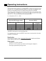
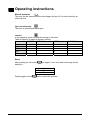
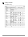
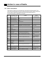
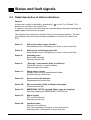
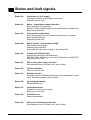
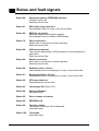
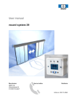
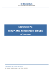
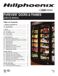
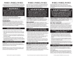
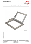
1
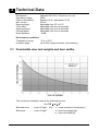
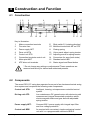
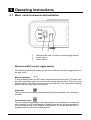
Automatic
Swing Door Operator
DFA 127 IN
(Inverse)
Operating instructions E
1.
2.
3.
4.
5.
6.
7.
8.
Page
General
2
Safety instructions
3
Technical data and operating conditions
4
Construction and function
5-6
Operating instructions
7 - 11
Configurations
12 - 13
Maintenance instructions
14
Action in case of faults
15 - 20
agtatec ltd
Allmendstrasse 24
CH-8320 Fehraltorf
Phone
+41 (0) 44 954 91 91
Fax
+41 (0) 44 954 92 00
Date: 12/2006, BU article-no.: 127.109.515 A
1 General
These operating instructions are intended for the record DFA 127 IN automatic
swing door operator (herein after referred to as DFA 127). The operator is the
person responsible for the technical maintenance of this door system.
These instructions describe the use of the record DFA 127 swing door operator.
They form the basis for satisfactory functioning.
These operating instructions should be read by the door operator before
commissioning and the safety instructions observed!
It is recommended to keep these operating instructions close to the automatic
sliding door.
Product designation:
Automatic swing door operator
Product name:
record DFA 127 IN
Serial number:
(please complete when installing)
Page 2 of 20
Rev. A 12/2006
Operating instructions DFA 127 Inverse
2 Safety instructions
The record DFA 127 swing door operator has been constructed in accordance with
the latest state of the art and the recognised technical safety regulations, including
limiting of forces and speeds. Nevertheless, danger can arise for the user if not
used as intended.
Installation, maintenance and repairs to the record DFA 127 must only
be performed by qualified and authorized personnel (technicians).
2.1 Use as intended
The DFA 127 swing door operator is constructed exclusively for normal service
with swing doors in dry rooms and must be installed within or inside buildings.
A different application or use extending beyond this purpose is not considered use
for the intended purpose. The manufacturer declines all responsibility for resulting
damage; the operator alone shall bear the associated risk.
Use for the intended purpose also includes observation of the operating conditions
specified by the manufacturer, including use and adjustment of the correct type of
arms, in addition to regular maintenance and repair.
Unauthorised modifications to the automatic door operator exclude any liability of
the manufacturer for resulting damage.
2.2 General safety and accident prevention regulations
In general no safety devices (sensors) may be dismantled or put out of
service.
During the learning cycle (which must only be performed by trained
personnel) the safety devices (sensors) are switched off! It must be
ensured, therefore, before initiating the learning cycle that no persons or
objects are situated in the danger zone of the moving door leaves during
the operation in order to avoid injury or damage!
No objects must be placed in the opening zone / path of the swing door
to avoid crushing and shearing points!
The safeguard for crushing and shearing strains at the side edge must
be provided by the manufacturer..
Operating instructions DFA 127 Inverse
Rev. A 12/2006
Page 3 of 20
3 Technical Data
Dimensions:
Operating voltage:
Power consumption:
Max. torque:
Opening angle:
Time delay:
Opening speed:
Closing speed:
Noise emission
Operator 600 x 85 x 124 mm (w x h x d)
230V∼
Standby 13 W, rated power 67 W
50 Nm
Adjustable from 70° to 115°
Adjustable from 0 to 20 seconds
Adjustable from 3 to 20 seconds
Adjustable from 5 to 20 seconds
-18 dB
Environment conditions
Temperature range:
Humidity range:
-15 to + 50°C
Up to 85% relative humidity, non bedewing
3.1 Permissible door leaf weights and door widths
The curves are calculated using to the following formula:
J = 1/3 × m × b2
Standard arms
Slide arms
Page 4 of 20
: J max. 65 kgm2
: J max. 65 kgm2
Key : J = mass moment of inertia [kgm2]
m = door leaf weight [kg]
b = door leaf width [m]
Rev. A 12/2006
Operating instructions DFA 127 Inverse
4 Construction and Function
4.1 Construction
1 2
3
4
13
12
14
5
10
11
Key to illustration:
1
Mains connection terminals
2
Fine-wire fuse
3
Power supply NET
4
Drive unit ATM
5
Control unit STG
6
Connection terminals control unit
7
Motor print MOT
8
ATE drive unit terminals
9*
10*
11
12
13*
14
15
16
6
7
9
15
8
16
Slide switch S1 (rotating direction)
Multifunctional switch MF on STG
Closing spring
Vision panel adjust. spring tension
Adjusting screw for spring tension
Connectors for arms (both sides)
Standard switch BDI
Status signal and Reset button
* Do not change any settings or adjustments! These operations are
reserved exclusively for trained and authorized persons.
4.2 Components
The record DFA 127 swing door operator forms part of an electromechanical swing
door system and comprises the following main components:
Control unit STG:
Intelligent, learning, microprocessor-controlled control
system.
Driving unit ATE:
Low maintenance DC geared motor with electronic path
measurement, integral thermostatic protective switch,
electro-magnetic brake and gear box with adjustable
spring tension.
Power supply NET:
Compact 230 V power supply with integral input filter
and over-voltage protection.
Control unit BDE:
As required with convenient, simple mechanical control
unit and / or a programmable electronic BDE-D.
Operating instructions DFA 127 Inverse
Rev. A 12/2006
Page 5 of 20
Construction and Function
Arm types:
Power transmission to the door leaf by use of standard
arm pushing or sliding arm pulling.
Locking VRR (optional): It is possible to connect an electrical door opener
(24VDC) to the operator.
Sensing units:
Aesthetic actuating and self-monitoring safety elements
with adjustable sensitivity ensure optimum, smooth and
reliable operation of the door system.
4.3 Functional description
The record DFA 127 with inverse function has been designed to open without
electrical power. It can be easily closed by hand and opens using the energy
stored in the spring, with the motion damped by the motor acting as a generator.
The door can be held closed without electrical power, for example, using the
escape door opener Type 331 or 332 from eff-eff (fire door: closed without
electrical power, escape and rescue route door: open without electrical power).
If the door operator is connected to the mains power, the opening and closing
movements will be assisted by the motor. There is thereby the possibility of fixing
the door leaves in the closed and/or open position (electro-magnetic brake).
In the standard "Automatic" mode of operation the door system opens by the
response of an actuating device (e.g. radar unit) to persons or objects
approaching. The door closes after the door hold-open time, provided no further
opening pulse is received.
In the "Lock" mode of operation, the door is only opened by actuation of an
optional key-operated contact (SSK). The door closes after the SSK door holdopen time, provided no further opening pulse is received.
An obstacle to the swing door leave during Closing leads to an immediate reopening (reverse). The obstacle position is recorded in the door operator and this
position is approached slowly when next closing. An obstacle to the swing door leaf
when Opening results in an immediate stop.
Page 6 of 20
Rev. A 12/2006
Operating instructions DFA 127 Inverse
5 Operating instructions
5.1 Mech. control elements and indication
1
1
2
3
2
3
Mechanic BDI with 3 positions (control toggle switch)
Reset button
Status signal
Mechanical BDI (control toggle switch)
The following operational modes can be set up with the 3-position toggle switch on
the side cover:
Manual operation
In this operating mode, the DFA can be opened and closed by hand. The door can
be easily opened by hand, but must then be closed again by hand. The door is only
held in position if the bolt can latch into an electrical lock. The connected actuating
devices are no longer taken into account.
Automatic
The door opens and closes automatically through the activation of an actuating
element.
Continuously open
The door opens and remains in the open position. If an obstacle is encountered
while opening, the DFA will attempt to bring the door to the set open position for
the next few seconds. If the obstacle is still present, the current position will be
accepted as the continuously-open position.
Operating instructions DFA 127 Inverse
Rev. A 12/2006
Page 7 of 20
Operating instructions
With the factory default setting, the mechanical BDI is always connected and active
on a DFA 127. If an additional electronic BDE-D is connected, the operating mode
will be set at the highest priority by a defined priority structure in the BDE.
The priority and the code shown in the following table apply to the operating mode,
whereby BDE2 (S2) and BDE1 (S1) represent the two input terminals of the control
unit (Æ J7/1 + J7/2, p.c.b. BDE-M) for the mechanical BDE:
(L = interruption or 0V, H = +24V)
Mechanical BDI (toggle switch)
BDE2
(S2)
L
H
L
BDE1
Electronic BDE-D
(S1)
H
L
L
Function
locked
one-way
continuously open
manual
automatic
Priority
(1=highest)
1
2
3
4
5
The BDE-D indicates the current operating mode.
If an operating mode is set on the BDE-D, which has no current priority, the status
message 62 is displayed.
Reset button
After pushing for approx. 5 sec. a new start of the control is performed (software
reset). After the reset the LED lights up permanently.
Status signal
-
Remains off if no fault is present.
-
Will blink if a fault is present (see status and fault signals / chapter 8)
-
Does light up permanently during a reset.
Page 8 of 20
Rev. A 12/2006
Operating instructions DFA 127 Inverse
Operating instructions
5.2 Auxiliary controls on the control unit STG 127
General:
The STG 127 operates with an active HIGH level, i.e. a +24 V level must be
applied to activate a function. Safety inputs are activated during interruptions.
The signal ground (0V) is connected to the protective earth.
Jumpers:
J14:
Master / Slave
jumper at position M1 for master (factory setting)
jumper at position S1 for slave
J13:
CAN line termination
LED’s:
LD1: (red)
control LED for push-button operation (S1)
LD2: (green) +35V
Off for power failure
LD3: (green) +24V
Lights if +24V present.
Caution: in the event of a power failure processor reset takes
place 1 second after this LED extinguishes.
Push button S1
This is a multifunctional switch on controller (MF).
The use of this switch is reserved exclusively for trained and authorized
persons.
Top view of the control unit STG:
Operating instructions DFA 127 Inverse
Rev. A 12/2006
Page 9 of 20
Operating instructions
5.3 Functions of electronic controller BDE-D (optional)
The BDE-D electronic controller is an easily
operated input and output device for the control
and adjustment of record door operators.
Logically arranged pushbuttons allow intuitive
operation and navigation through the operatorspecific menu. The LCD with backlight shows
data and information about the door status with
symbols and text messages.
Additional information can be found in the BDE-D
manual (No. 903 109 271).
5.4 Operation modes
Automatic
Normal function
Table to signals (X marks a release reaction)
CLOSED OPENING
AKI
x
x
AKA
x
x
SSK
x
x
x
SIO
SIS
OPEN
x
x
x
x
x
CLOSING
x
x
x
x
x
One-way traffic
In one-way traffic mode people cannot enter the room from the outside but they
can leave it from the inside.
Table to signals (X marks a release reaction)
CLOSED OPENING
OPEN
CLOSING
AKI
x
x
x
x
AKA*
x
x
x
SSK
x
x
x
x
x
SIO
x
x
SIS
x
x
* AKA is active as safety device while closing
Page 10 of 20
Rev. A 12/2006
Operating instructions DFA 127 Inverse
Operating instructions
Manual operation
The door can be opened and be closed again by hand if it is held closed by an
electrical lock.
Open continuously
The door is opened and stays open.
Locked
In the operation mode Locked the locking is activated.
Table to signals (X marks a release reaction)
CLOSED OPENING
OPEN
AKI
x
x
AKA
x
x
SSK
x
x
x
x
SIO
x
SIS
x
Reset
After pushing on the button
display is:
CLOSING
x
x
x
x
x
for approx. 5sec. this status message on the
No
Reset Operator?
Yes
Pushing again on the
Operating instructions DFA 127 Inverse
button resets the operator.
Rev. A 12/2006
Page 11 of 20
6 Configurations
6.1 Parameter Overview
Page 12 of 20
Rev. A 12/2006
Operating instructions DFA 127 Inverse
Configurations
Configurations of the DFA 127 can only be made with the electronic BDE-D. If a
toggle switch is connected, a BDE-D must be connected briefly for the
configuration.
Further information for parameter changes can be taken from the user manual of
the BDE-D (no. 903 109 271).
Please always leave the configuration review sheet in the drive!
6.2 Parameter description
Parameter
DRIVING CYCLE
Closing speed
Opening speed
TIME DELAY
OPEN
Time delay open
Time delay SSK
DRIVE
Opening angle
Setting
range
Factory
default
Description
0 - 40
(5 – 20 s)
0 - 40
(3 - 20 s)
18
Slider control with 40 steps
36
Slider control with 40 steps
0 - 40
(0 - 60 s)
2
0 – 40
(0 - 60 s)
4
Effective with AKA, AKI and push to
actuate
0 - 20: Steps of 1 s
21 - 40: Steps of 2 s
Effective with SSK
0 - 20: Steps of 1 s
21 - 40: Steps of 2 s
0 - 40
35
Operating instructions DFA 127 Inverse
Rev. A 12/2006
The opening angle is estimated
during the calibration run and is
equivalent to the value of 40.
Page 13 of 20
7 Maintenance instructions
7.1 General
The record DFA 127 swing door operator is a product of the latest technology. It has
been carefully made and only leaves the factory following thorough testing.
Automatic swing doors should be operated and maintained to ensure safety at all
times.
7.2 Care
The entire swing door system can be cleaned with a damp cloth and commercially
available cleaning agents. The cleaning agent must be harmonised to the surface
which has to be cleaned.
It is recommended to select the "Continuously open" or "Locked" mode of operation
for this purpose, so that the door does not continually open and close unnecessarily.
7.3 Maintenance, periodic inspection
It is recommended to have a technical safety test with servicing performed by a
specialist before first commissioning and as required, but at least twice a year.
Regular testing and servicing by our fully trained personnel therefore offers the best
guarantee for a long service life and satisfactory operation. We therefore
recommend the signing of a maintenance agreement. Our service department will
be pleased to submit a proposal.
If nevertheless a fault should occur, which you cannot eliminate (see section 8) our
service organisation or the maintenance personnel of our agents are available.
7.4 Service centres
In Switzerland: Phone +41 (0) 44 954 92 92 / Fax +41 (0) 44 954 92 00
Alternative service centre: _____________________________________________
Page 14 of 20
Rev. A 12/2006
Operating instructions DFA 127 Inverse
8 Action in case of faults
8.1 Fault indication
Various indications are given for an irregularity or fault depending on the control
unit connected BDE-E or BDE-M.
When using a mechanical BDE (control toggle switch)
With the mechanical control unit it is not possible to display a detailed status signal.
If a fault occurs (will be shown by the status signal on the side cover), please
proceed according to section 8.2.
When using an electronic BDE-D
General
Any current operational faults in the drive system will be displayed in the Standard
screen. If several faults are active, they will be numbered: e.g. Fault 1/2
In case of an irregularity the display changes automatically from mode of operation
level to error display. Every 2 seconds the backlight changes between normal
/invers. Several errors can be displayed (e.g. 1/2 means: error no. 1 of total 2
errors).
After 10 seconds the telephone number of the responsible service centre is
indicated alternating to the fault indication. The failure indication and the phone
number change every 5 seconds, while the inverse flashing is remaining. The
described sequence applies to all failures. However, previously the phone number
must have been given by an authorised specialised person.
Information about the drive system, such as the software version, can be read out
by pressing the
key.
After pressing this key once again, the phone number of the responsible service
centre and the last appeared fault indication is displayed in the screen. If the fault
message consists of several lines the first line will be displayed only.
Status signals with a "W" are warnings. For these the fault relay contact output is
not connected. Elimination of the irregularity leading to the status signal is
performed according to section 8.2
A status can usually be deleted by pressing the
key for 5 s (= Reset). This
produces a new start in the control unit.
If, however, the cause of the fault has not been eliminated, the status message will
appear again if the fault occurs again.
Operating instructions DFA 127 Inverse
Rev. A 12/2006
Page 15 of 20
Action in case of faults
8.2 Error elimination
The majority of faults can be eliminated by consulting the following table. If the
fault cannot be eliminated even after working through the table, please contact the
service centre. Please also contact the service centre directly when no
recommended action is specified in the table.
Status
Symptom, fault,
door behaviour
03
Door remains open
05
Door remains open
06
Door does not unlock
Cause
Action
(consult service if no
recommend-action)
Actuating device inside active longer than
60 s
Actuating device outside active longer than
60 s
Unlocking fault
23
Control unit SLAVE defective
Reset by service fitter
25
MASTER / SLAVE connection interrupted
Reset by service fitter
Release EMERGENCY
STOP button
31
Door stops
EMERGENCY STOP button operated
37
Door stops
Faulty motor current
38
Door changes to manual
Excess temperature motor
control
Peripheral devices take
Overload on +24 V supply
too much power
Wait until motor has
cooled
41
Door stops
Motor 1 thermal sensor defective
Reset by service fitter
43
Door stops
Incremental transmitter defective
45
Minimum hold-open time
Motor current time product too large
increased to 20 secs.
46
Door stops
39
47
50
Reset by service fitter
Reset by service fitter
Wait until motor has
cooled
Control unit defective
Reset by service fitter
Door remains closed
SIO sensor longer activ than 60 sec.
Remove obstacle from
surveillance range of
sensor
Door stops
Control unit defective
Reset by service fitter
No valid drive parameter
Initiate calibration run
52
53
Door stops
Interruption motor
Reset by service fitter
54 W
Door jolts possibly while
opening
Calibration run
Initiate 1 opening cycle
Door stops
SIS sensor longer activ than 60 sec.
Remove obstacle from
surveillance range of
sensor
60
Door stops
Parameter memory defective
Reset by service fitter
61
Door remains open
Key operated contact active longer than 60
s
Release key contact
62 W
Higher-order mode of
operation present
Control unit BDE has no priority
Cancel higher-order mode
of operation
59
Page 16 of 20
Rev. A 12/2006
Operating instructions DFA 127 Inverse
Status and fault signals
8.3 Detail description of status indications
General
A status can usually be deleted by pressing the
key for 5 s (= Reset). This
produces a new start in the control unit.
If, however, the cause of the fault has not been eliminated, the status message will
appear again if the fault occurs again.
The following list contains the causes of faults in decreasing possibility. The fault
at the bottom of the list has the smallest probability to occur in the control unit
STG.
Status 3:
AKI sensor active longer than 60 s
Automatically reset if everything is in order, or by service fitter
Status 5:
AKA sensor active longer than 60 s
Automatically reset if everything is in order, or by service fitter
Status 6:
Unlocking error
Bolt possibly jammed
Reset by service fitter
Status 9:
“Opening” unsuccessful (after 4 collisions)
Check the interlock / remove obstacle
Reset through service fitter
Status 11:
Faulty motor current
Possibly faulty wiring in prefabricated cables
Replacement by service fitter
Status 23:
Slave control unit defective
Replacement by service fitter
Status 25:
Slave connection (CAN) to Master interrupted
Clear by service fitter
Status 31:
EMERGENCY STOP operated. Motor relay de-energises
Reset by resetting the EMERGENCY STOP button
Status 37:
Motor current
STG or ATE defective
Reset by service fitter
Status 38:
Overheat motor
Manual control effective
Door leaves possibly too heavy, or too much friction
Reset by motor cooling down or by service fitter
Operating instructions DFA 127 Inverse
Rev. A 12/2006
Page 17 of 20
Status and fault signals
Status 39:
Overload on + 24 V supply
Too many external units possibly connected
Reset by service fitter
Status 41:
Motor – temperature sensor defective
Motor possibly not connected
Sensor in motor possibly defective or cable break in sensor lead
Reset by service fitter
Status 43:
Incremental encoder fault
Input cable possibly not connected or cable break in the lead
Motor possibly blocked
Reset by service fitter
Status 45:
Motor current – time product to high
Motor relay de-energises
Manual control effective
Automatic reset by motor cooling or by service fitter
Status 46:
Control unit STG defective
Includes the following individual faults:
EPROM, RAM, Watchdog, Imax, ImaxT, difference on SHE-EXT
Reset by service fitter
Status 47:
SIO sensor active longer than 60 s
Automatically reset if in order, or by service fitter
Status 50:
CPU2 is defective
Reset by service fitter
Status 51:
Software version
Software version of Master and Slave do not correspond to each
other. Software update by service fitter
Status 52:
No running parameter
Start calibration run
Status 53:
Interruption motor
Possibly no connection to motor
Reset by service fitter
Status 54:
Calibration run
Reset automatically
Status 59:
SIS sensor active longer than 60 s
Automatically reset if in order, or by service fitter
Page 18 of 20
Rev. A 12/2006
Operating instructions DFA 127 Inverse
Status and fault signals
Status 60:
Parameter memory (EEPROM) defective
Change control unit
Reset by service fitter
Status 61:
SSK active longer than 60 s
Automatically reset if in order, or by service fitter
Status 62:
BDE has no priority
Because a higher-level signal is present
Automatically reset on release of BDE-button
Status 72:
Slave connection
Master has no connection to Slave operator
Reset by service fitter
Status 88:
Difference parameter
The common parameters of M/S operators do not correspond to
each other.
Reset by service fitter
Status 89:
Master connection
Slave has no connection to master operator
Reset by service fitter
Status 90:
Railbeam active > 60 sec.
Automatically reset if everything is in order, or by service fitter
Status 91:
Bodyguard active > 60 sec.
Automatically reset if everything is in order, or by service fitter
Status 92:
STG relay defective
Replacement by service fitter
Status 93:
Overvoltage 24 V (from 27V)
Status 94:
Spring calibration
Automatic reset
Status 95:
Error in sense of rotation
Status 96:
EEPROM void
Status 99:
Operator rotates
The grease in the gear will be dispersed.
Automatic reset
Status 105:
Test brake
Automatic reset
Operating instructions DFA 127 Inverse
Rev. A 12/2006
Page 19 of 20
Status and fault signals
Status 106:
Brake defective
Reset or reset by service fitter
Status 107:
SIS defective
A safety sensor (with test input) in closing direction is defective.
Reset by service fitter
Status 108:
SIO defective
A safety sensor (with test input) in opening direction is defective.
Reset by service fitter
Status 109:
Factory settings
Status 110:
No motor
No motor detection during initialisation (motor temperature sensor).
Check motor temperature sensor.
Reset or reset by service fitter
A status number with a "W" is a warning !!
Page 20 of 20
Rev. A 12/2006
Operating instructions DFA 127 Inverse