1
Installation and maintenance
Please keep careful!
TAC4 DG + GRC
Operating Instructions
Control unit
Status: 06/2013
Paul Wärmerückgewinnung GmbH
August-Horch-Straße 7
08141 Reinsdorf
Germany
Tel.: +49(0)375 - 303505 - 0
Fax: +49(0)375 - 303505 - 55
Table of contents
0
Preamble ................................................................................................................................. 3
1
Introduction ............................................................................................................................ 3
1.1
1.1.1
Safety ....................................................................................................................................... 3
Used symbols........................................................................................................................... 3
2
Functionalities of the regulation .......................................................................................... 4
3
Generell maintenance instructions ...................................................................................... 5
3.1
3.1.1
3.1.2
3.1.3
Generell information ................................................................................................................. 5
Generell schematic of the maxi-series ..................................................................................... 5
Schematic of the T° sensors positioning in the maxi unit ........................................................ 6
Control panel 3 label located inside the cover ......................................................................... 6
4
GRC wiring and funtionalites................................................................................................ 7
4.1
4.1.1
4.1.2
Installation of GRC ................................................................................................................... 7
On wall installation ................................................................................................................... 8
In wall installation ..................................................................................................................... 8
4.2
4.2.1
4.2.2
4.2.2.1
4.2.2.2
4.2.3
Wiring of GCR TAC4 ................................................................................................................ 9
Plug SAT MODBUS satellite on CB4 TAC4 DG ...................................................................... 9
Wiring diagram to connect the GRC TAC4 REC to the SAT MODBUS ................................ 10
Cable specifications ............................................................................................................... 10
Wiring several circuits on one GRC ....................................................................................... 10
Power GRC TAC4 .................................................................................................................. 11
4.3
Selecting the master .............................................................................................................. 11
4.4
Fan control ............................................................................................................................. 12
4.5
4.5.1
Time slots schedules ............................................................................................................. 13
Definition ................................................................................................................................ 13
4.6
4.6.1
4.6.2
4.6.3
4.6.4
4.6.4.1
4.6.4.2
Alarms .................................................................................................................................... 13
Alarm types ........................................................................................................................... 13
Alarm table ............................................................................................................................. 15
Wiring diagrams ..................................................................................................................... 16
Fire alarm ............................................................................................................................... 16
Configuration .......................................................................................................................... 16
Wiring diagram of fire alarm ................................................................................................... 16
4.7
4.7.1
4.7.2
BOOST function ..................................................................................................................... 17
Setup ...................................................................................................................................... 17
Wiring diagram ....................................................................................................................... 17
4.8
BYPASS function (free cooling) ............................................................................................. 17
4.9
Opening / closing of dampers (CT option) at inlet ................................................................. 18
4.10
4.10.1
4.10.2
Heat exchanger antifrost protection system .......................................................................... 18
Protection antifreeze via pulse flow reduction ....................................................................... 18
Antifrosting the heat exchanger with 1 pre-heating KWin (option) ........................................ 19
4.11
4.11.1
KWout post heating electrical coil control (option) ................................................................. 20
Wiring diagrams ..................................................................................................................... 20
4.12
4.12.1
Post heating (NV option) regulation ....................................................................................... 20
Wiring diagrams ..................................................................................................................... 21
4.13
Regulation for external coil(s) (SAT TAC4 BA/KW option) .................................................... 22
4.14
Fan failure alarm .................................................................................................................... 23
1
4.15
Actual airflow / pressure output signals ................................................................................. 23
5
Configuration and use ......................................................................................................... 24
5.1
Principles of GRC TAC4 ........................................................................................................ 24
5.2
5.2.1
5.2.1.1
5.2.1.2
5.2.1.3
5.2.2
5.2.2.1
5.2.2.2
5.2.2.3
5.2.3
5.2.3.1
5.2.3.2
5.2.3.3
5.2.4
Setup and fan control ............................................................................................................. 25
CA mode: setup, operating instructions and wiring diagrams................................................ 25
Setup CA mode ...................................................................................................................... 25
Operating CA mode with GRC TAC4 master (‘Control’ screen) ............................................ 27
Operating CA mode with TAC4 DG master ........................................................................... 27
LS mode: setup, operating instructions and wiring diagrams ................................................ 28
Setup LS mode ...................................................................................................................... 28
Operating LS mode with GRC TAC4 master (‘Control’ screen)............................................. 30
Operating LS mode with TAC4 DG master ............................................................................ 31
CPs mode: setup, operating instructions and wiring diagrams .............................................. 32
Setup CPs mode .................................................................................................................... 32
Operating CPs mode with GRC TAC4 master (control screen)............................................. 34
Operating CPs mode with TAC4 DG master ......................................................................... 35
Mode OFF .............................................................................................................................. 35
5.3
5.3.1
5.3.2
5.3.3
Time slots schedules.............................................................................................................. 36
«Setup» tab ............................................................................................................................ 36
«Week planner» tab ............................................................................................................... 37
«Year planner» tab (seasonally or yearly planner) ................................................................ 37
5.4
5.4.1
5.4.2
5.4.3
5.4.3.1
5.4.3.2
Network management ............................................................................................................ 37
General................................................................................................................................... 37
Network Visualization ............................................................................................................. 38
Edit a network ........................................................................................................................ 38
Screen description ................................................................................................................. 38
Method ................................................................................................................................... 38
5.5
5.5.1
5.5.1.1
5.5.1.2
5.5.1.3
5.5.1.4
5.5.1.5
5.5.2
5.5.3
5.5.4
5.5.5
5.5.6
Visualization ........................................................................................................................... 39
«Synoptic» tab ....................................................................................................................... 39
General information................................................................................................................ 39
Air «Flows» tab ...................................................................................................................... 40
Post heating information (if NV or KWout or BA+ option present) ......................................... 40
Anti-frost information .............................................................................................................. 42
Damper(s) (CT) information (option) ...................................................................................... 42
«Alarms» tab .......................................................................................................................... 43
«Setup» tab ............................................................................................................................ 43
«Flows» tab ............................................................................................................................ 44
«I/O» tab................................................................................................................................. 44
«Config» tab ........................................................................................................................... 45
5.6
Advanced setup ..................................................................................................................... 45
2
0 Preamble
PLEASE READ THIS MANUAL CAREFULLY BEFORE INASTALLATION AND COMMISSONING!
THIS MANUAL HAS BEEN MADE WITH GREATEST CARE.
HOWEVER, NO RIGHTS CAN BE DERIVED THEREFROM. WE RESERVE THE RIGHT AT ANY TIME
TO PARTIALLY OR ENTIRELY CHANGE THE CONTENT OF THIS MANUAL WITHOUT PRIOR
NOTICE.
This manual contains all the best for an assembly plant and a heat recovery unit (HRU) necessary
information. The manual also serves as a handbook for installation, maintenance and customer service
work. We recommend that any intervention in the appliance installation company should be consulted.
Subject of this operating manual is the control unit TAC4 with the operating unit GRC TAC4. Possible
accessories are only described insofar as it is necessary for the appropriate operation. Please see the
particular manuals for further information on accessories.
If you have any questions that have not been answered or have not been sufficiently answered in this
documentation, please contact the company Paul Wärmerückgewinnung GmbH. We will be glad to help
you.
1 Introduction
1.1
Safety
Please always observe the safety instructions in this operating manual. The non-observance of the safety
instructions, warning notices, notes and instructions can lead to injuries or damages to the maxi.
• Unless otherwise stated in this operating manual, only an authorised installer is entitled to install,
connect, put into operation and maintain the maxi;
• The installation of the maxi is to be performed according to the general local building, safety and
installation instructions of the corresponding local authorities, of the water works and electric
works and other official regulations and directives;
• Always follow the safety instructions, warning notices, notes and instructions described in this
operating manual;
• Please keep this manual during the complete life time of the maxi in proximity to the device;
• The instructions for the regular replacement of the filters or the cleaning of the supply and exhaust
air valves are to be strictly followed;
• The specifications stated in this document may not be changed;
• Any modification of the maxi is prohibited;
• In order to guarantee that the device will be regularly controlled, it is recommended to conclude a
maintenance contract. Your supplier can give you the addresses of authorised installers in your
area.
1.1.1
Used symbols
The following symbols are used in this manual:
Caution, special note!
Risk of:
- injury of the user or the installer
- damages to the device
- impairment of the operation of the device if the instructions are not
carried out properly
3
2 Functionalities of the regulation
The TAC4 DG controller is mounted in the units of maxi-series.
This handbook describes the functionalities of the TAC4 DG when using a GRC TAC4 display. A
SAT MODBUS satellite (option) is used to connect the graphic remote control (GRC).
The TAC4 DG with GRC TAC4 controller provides the following features:
• Monitoring of the fans (exhaust and supply) in chosen working mode: constant airflow (CA),
constant pressure (CPs) or constant airflow linked to 0-10V signal (LS) (e.g. CO2 sensor).
• Management of 6 timeslots.
• Alarms on defects, set points, overpressure.
• Fire alarm airflow management.
• BOOST function, allowing to force a pre-set airflow (supply/exhaust), overriding the assigned
airflow
• Automatic management of the 100% bypass to allow free cooling.
• Automatic management of inlet dampers (CT).
• Heat exchanger antifreeze protection system by modulation of airflow or with an intelligent preheat electrical coil (KWin).
• Post heating management of water coil (NV) or electrical coil (KWout) battery to keep a set
temperature constant.
The following options can be combined with TAC4 DG controller:
•
•
4
SAT TAC4 BA/KW Option:
Regulation of 2 external heat exchangers (electrical/water, hot and/or cold).
SAT TAC4 MODBUS Option:
MODBUS RTU communication (please refer to TAC4 DG - MODBUS RTU installation and user’s
manual for detailed information).
3 Generell maintenance instructions
3.1
3.1.1
Generell information
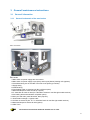
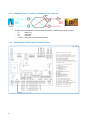
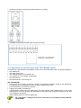
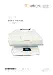
Generell schematic of the maxi-series
3
Maxi flat-series
Maxi-series
1 Main switch for power supply fans and control
2 Main switch for power supply to pre (Kwin) and/or post (Kwout) heating coils (options)
3 Centralized wiring box of the CB4 TAC4 DG circuit (factory pre-wired)
4 Supply fan(s)
5 Exhaust fan(s)
6 Post-heating water or electrical coil (NV or KWout option)
7 Motorized damper at fresh air inlet (CT option)
8 F7 class filter at fresh air inlet (G4- class filter extract air maxi flat right model versions)
9 Pre-heating electrical antifreeze coil (KWin option)
10 Drain pan and drain (maxi flat-series: drain pipe out)
11 Air/Air heat exchanger + bypass 100%
12 G4 filter on extract air (G4- or F7- class filter fresh air maxi flat right model versions)
13 Motorized damper at extract air inlet (option)
14 GRC TAC4
All electrical connections made the installer are in 1/2/3.
5
3.1.2
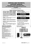
Schematic of the T° sensors positioning in the maxi unit
To allow easier identification of the temperature sensors 4 different wire colors are used:
-
3.1.3
6
T1 :
T2 :
T3 :
T4 & T5 :
black wire
white wire
blue wire
green wire (not at maxi flat-series)
Control panel 3 label located inside the cover
4 GRC wiring and funtionalites
The regulation is delivered fully factory pre-wired. Nevertheless, the TAC4 GRC (graphic remote control)
and the i/o signals if any must still be wired by the installer.
4.1
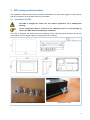
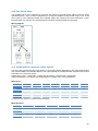
Installation of GRC
The GRC is designed for indoor use. For outdoor application, use a weatherproof
housing.
All the configuration data is enclosed in the TAC4 DG circuit. It is thus possible to
remove the GRC without disrupting the installation.
The GRC is delivered with attachments and fastening screws. Mounting panel thickness should not
exceed 5mm. The rectangular indent in mounting panel is 147x82mm.
Attachment mounting brackets
Attachment on GRC
7
4.1.1
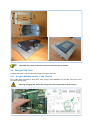
On wall installation
This kit GRC includes a box with an opening in the lid where the GRC touchscreen fits perfectly.
4 fixations
130
220
85
170
180
Fix the GRC in the lid with the mounting brackets supplied in the GRC kit GRC.
The cable entry holes in the box will have to be done by the installer.
4.1.2
In wall installation
This kit GRC allows the touchscreen GRC to be flush mounted in a wall. It includes a box and a stainless
steel front panel on which the GRC can be fixed.
8
150
120
205
175
Fix the GRC in the stainless steel panel with the mounting brackets supplied in the GRC kit.
The cable entry holes in the box will have to be done by the installer.
4.2
Wiring of GCR TAC4
Follow these steps to connect the GRC TAC4 to the CB4 TAC4 DG:
4.2.1
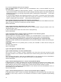
Plug SAT MODBUS satellite on CB4 TAC4 DG
First, make sure the power is shut down, then plug the SAT MODBUS on the CB4 TAC4 DG circuit
connector (see picture).
Warning: plugging the SAT in the wrong connector can be fatal to both circuits !
9
4.2.2
Wiring diagram to connect the GRC TAC4 REC to the SAT MODBUS
A+
=
B=
GND =
black wire
brown wire
metal wire
4.2.2.1 Cable specifications
• Recommended cable: category 5 shielded twisted pair (FTP) cable with a section of 0,26 … 0,50 mm².
Use 1 pair to connect GND and +12V and 1 pair to connect B- and A +.
• Maximum cable length: 1000 m.
• Keep this communication cable at distance from power cables..
• If the unit is installed in a location with high electro-mechanical interference levels we strongly advise
to connect the armored shield of the TAC4 DG – GRC cable on one side of the ground only.
• If the maxi-series is installed outside, select a suitable cable for outdoor application (UV light, …).
4.2.2.2 Wiring several circuits on one GRC
• The maximum number of circuits that can be connected on one GRC is 247 units (manual monitoring).
• The "network" screen can only monitor 5 units at a time (automatic monitoring).
• Wire specifications between 2 SAT MODBUS: shielded twisted pair (FTP), category 5, Section of
0.26... 0,50 mm². Use same pair to connect B - and A +. The circuits shall be connected in series as
shown on the wiring diagram below.
Wiring diagram
10
4.2.3
Power GRC TAC4
Use a 24 Vdc power supply. Maximum power consumption is 5W. The TAC4 DG provides a 24Vdc output
for this purpose. See wiring diagram below.
A + = black wire
B= brown wire
GND = metal wire
+ = Vo
- = GND
Same wiring is applied in case an NV option is used (3 way valve power supply). Be
extra careful to wire ‘properly’, as improper wiring can cause malfunctioning of the
installation.
4.3
Selecting the master
«Selecting the master» means the determination of which module of the i/o and the RC will “control” the
fans, “controlling” the fans means:
- If CA mode is chosen (§ 5.2.1), to be the master means to control the start/stop of the fans as well as to
select the airflow
- If LS or CPs mode (§ 5.2.2 and 5.2.3), to be the master means to control the start/stop of the fans as
well as to activate/deactivate a different assignment (assignment multiplier).
2 setups are possible:
1) Or TAC4 DG circuit is «master»: contact between terminals IN1 and +12Vdc of TAC4 DG circuit is
closed.
- The TAC4 DG circuit allows control of the fans through its inputs.
- The GRC TAC4 allows to configure and to clearly visualize all the parameters,
2) Or GRC TAC4 is « master »: contact between terminals IN1 and +12Vdc of TAC4 DG circuit is open.
- The TAC4 DG circuit is then in control of the system and serves as a control hub between fans and the
GRC TAC4.
- The GRC TAC4 allows to configure and to visualize all the parameters on the display screens,
- The GRC TAC4 controls the fans
TAC4 DG circuit is master
Control
GRC TAC4 is master
Visualization
Control
Visualization
11
Wiring diagram
Contact closed = TAC4 DG circuit master
Contact open = GRC TAC4 master
Caution: Use gold-plated contact only.
The use of this contact enables to switch automatically from GRC TAC4 master to TAC4 DG master.
Using this you can for instance:
4.4
•
Work in GRC TAC4 master and switch in position TAC4 DG master to stop automatically the
fans (attention, in this case the inputs K1/K2/K3 on the TAC4 DG have to be disconnected from
the +12V).
•
Work in GRC TAC4 master and switch in position TAC4 DG master to activate automatically a
sleep value (attention K1/K2/K3 on the TAC4 DG have to be properly connected to activate this
value).
Fan control
The various working modes give the user the choice on how the airflow must be modulated according to
your application.
In all the working modes the supply fan will operate according to the assigned mode and parameters.
The airflow of the exhaust fan will then equal to a percentage of the actual airflow of the supply fan (noted
%EXT / PUL for ratio between exhaust and supply airflows).
The GRC TAC4 allows configuration of one of the following 4 modes:
• CA MODE:
3 constant airflow assignments for the supply fan are determined by the user (m³h K1, m³h K2 and
m³h K3).
• LS MODE:
The assigned supply airflow is a function of a 0-10V linear signal. The user defines the link with 4
parameters: Vmin, Vmax, m³h≡Vmin and m³h≡Vmax, applied to the following diagram:
With m³h≡Vmin < or > m³h≡Vmax (positive or negative link).
Using the advanced setup, it is possible to stop the fans once the
input signal value has reached a certain upper and/or lower limit.
•
12
CPs MODE:
CPs on supply: the airflow of the supply fan(s) is modulated so as to maintain constant a certain
pressure value measured by a pressure sensor properly located in the ducting.
CPs on exhaust: the airflow of the exhaust fan(s) is modulated so as to maintain constant a certain
pressure value measured by a pressure sensor properly located in the ducting.
• MODE OFF:
Is not a real working mode, it is a way to temporarily shortcut the TAC4 DG master setup. It allows, if
working in TAC4 DG master, to stop the fans with the GRC TAC4. But then to restart the fans it is
required to choose one of the other 3 working modes.
4.5
4.5.1
Time slots schedules
Definition
The TAC4 DG regulation allows to configure up to 6 time slots per day.
For each time slot select:
• The exhaust and the supply airflows:
o Working mode (CA, LS, CPs or OFF)
o CA mode: select the actual exhaust and supply airflow
o LS mode : select a % value of the link configured as well as a %age value of the
unbalance between exhaust and supply airflows (% exhaust/supply)
o CPs mode : select a %age value of the reference pressure as well as a %age value of
the unbalance between exhaust and supply airflows (% exhaust/supply)
• Bypass status: choose either automatic (see § 4.7) or either «force» the bypass to «open» or
«close» for the TSi considered.
• If post heating installed (option): set the assignment t° for the supply air for the TSi considered
• If post-cooling installed (option) set the assignment t° for the supply air for the TSi considered
Seasonal management is also possible :
• Force bypass ‘close’ between 2 dates (avoid free cooling in the winter)
• Disable the post-heating feature between 2 dates (avoid post heating in the summer)
• Disable the post-cooling feature between 2 dates (avoid cooling in the winter)
4.6
4.6.1
Alarms
Alarm types
The TAC4 DG features 14 alarms types divided in 9 categories (alarms table in § 4.5.2 ).
Type 1: Alarm indicating a fan failure (1).
This alarm indicates a failure of fan Fx. Main cause for this alarm is power supply to the motor or the
motor itself. Check also the wiring and fan connections to TAC4 DG circuit.
See 1 in table 4.5.2 below.
Type 2: Alarm on the pressure variation (CA and LS modes only).
This alarm indicates a pre-established pressure level has been reached on fan Fx.
Pressure alarm setup in CA or LS mode (see § 5.2.1.1 and 5.2.2.1).
See 2 in table below.
Type 3: Alarm indicating a problem while initializing reference pressure for a pressure alarm (1).
4 possibilities:
• Actual airflow < requested airflow : The requested working point is ‘too high’ (too much pressure) for the
maximal available pressure at the requested airflow for this fan.
• Actual airflow > requested airflow: the nominal airflow requested to initialize the pressure alarm cannot
be reached because the lower limit of the fan’s operating zone has been reached.
• Very unstable pressure (pumping).
• Assigned airflow not reached after 3 minutes.
See 3 in table below.
13
Paréf cannot be identified and the fans are stopped.
Press « ALARMS RESET» in «Alarms» tab of the «Visualization» menu, or with the ‘RESET’ key on the
TAC4 DG circuit.
- If it occurs during initializing an alarm pressure 2 options: 1. No action is taken: the control will operate
without pressure alarm 2. Corrective action is taken (change the working point to one well located in the
working zone of the fan, by reducing the pressure system, modifying the nominal airflow,… ) and restart
the setup operation.
- If it occurs during initializing of the assignment pressure in CPs mode : A corrective action must be taken
(change the working point to one well located in the working zone of the fan, by reducing the pressure
system, modifying the nominal airflow, …) and restart the setup operation.
Type 4: Alarm indicating the system cannot fulfill the assignment (1).
The assignment (keeping certain airflow or a certain pressure constant) cannot be fulfilled because the
upper or lower limit of the fan’s working zone has been reached.
See 4 in table below.
Type 5: Alarm indicating a data failure in the control circuit.
Crucial data from the circuit board has been lost. Try a TOTAL RESET using the «Admin» tab in the
«Advanced Setup» menu.
If still not solved send the defect TAC4 DG circuit for reprogramming.
See 5 in table below.
Type 6: Fire Alarm with an external contact connected to a fire detection system.
See 6 in table below. For more details, see § 4.5.4.
After a fire alarm it is necessary to perform a RESET (use «ALARMS RESET» in the «Alarms» tab of the
«Visualization» menu or the RESET button on the TAC4 DG circuit to return to normal operation).
Type 7: Alarm indicating maintenance is expected. (for configuration see “advanced setup):
SERVICE ALARM: indicates the fan operating time (in hours) has exceeded a certain limit set during the
configuration.
STOP FAN: indicates the fan operating time (in hours) has exceeded a certain limit set during the
configuration.
This alarm stops the fans.
See 7 in table below.
Type 8: Not applicable with GRC TAC4.
Type 9: Alarm indicating a T° sensor T1/T2/T3 failure.
One or more of the T° sensors T1/T2/T3 connected to the TAC4 DG circuit and mounted on heat
exchanger is defect or not connected. These sensors are crucial for the by-pass control and the antifrost
procedure.
After correction of the failure, reset using «ALARMS RESET» in the «Alarms» tab of the «Visualization»
menu or the RESET button on the TAC4 DG circuit to return to normal operation.
See 9 in table below.
Type 10: Alarm indicating failure on T° sensor T4 (only with NV option).
It indicates that the T° sensor T4 located on the coil and connected to the TAC4 DG circuit is defect (open
or short circuit) or not connected. This sensor is used to avoid frosting of the NV coil. In this case, as a
safety measure, the 3 way valve is opened and the contact used to start the circulator is closed.
After fixing the failure, reset using «ALARMS RESET» in the «Alarms» tab of the «Visualization» menu, or
press RESET on the TAC4 DG circuit.
See 10 in table below.
Type 11: Alarm indicating failure on T° sensor T5 (only with NV option or KWout).
It indicates a failure of the T° sensor T5 located in the supply duct and connected to the TAC4 DG circuit
(opened or short circuit) or that it is not connected. This sensor is used to regulate the post-heating
function.
14
After fixing the failure, reset using «ALARMS RESET» in the «Alarms» tab of the «Visualization» menu or
press RESET on the TAC4 DG circuit.
See 11 in table below.
Type 12: Alarm indicating that the assigned T° cannot be reached (only with NV option or KWout).
If the actual T° is lower than the assigned T° for more than 15 minutes with the post-heating fully opened
until)
See 12 in table below.
Type 13 et 14: Alarm indicating antifrosting alert (only with KWin option).
In certain air T° conditions as measured on the exhaust airflow after the heat recovery, indicating that the
Kwin has reached its limit, the TAC4 DG control can take over to guarantee the antifrost function.
a) Alarm type 13: If T° < assignment T°-1,5°C for more than 5 minutes: supply and exhaust airflow
reduction of 33% if CA or LS and of 25% if CPs, for 15 minutes.
b) Alarm type 14: If T° < -5°C during 5 minutes, fans are stopped. Reset using «ALARMS RESET» in the
«Alarms» tab of the «Visualization» menu, or press RESET on the TAC4 DG circuit to restart the unit.
See 13 & 14 in table below.
4.6.2
Alarm table
Actions on GRC
TAC4
LED
LED Pa
Alarm
Category
Type
Fans
1
Red
/
Pressure
2
/
Init Pa
Set point
Software
Fire alarm
3
4
5
6
Maintenance
/
T° sensors
T° sensors
T° sensors
Set point
Anti freeze
Anti freeze
Actions on the TAC4 DG circuit
AL1 relay
Action on
fans
LED AF
Alarm status
R2 relay
of SAT3
(O.R.1)
/
/
Stopped
Red
/
Closed
/
Red
Red
Red
Red
/
/
/
/
Alarm status
/
Alarm status
Alarm status
/
/
/
/
/
/
/
/
7 a)
Red
/
Alarm status
/
/
/
(1)
Stopped
/
Stopped
Stopped
(2)
/
7 b)
8
9
10
11
12
13
14
Red
/
Red
Red
Red
Red
Red
Red
/
/
/
/
/
/
/
/
Alarm status
/
Alarm status
Alarm status
Alarm status
/
/
Alarm status
/
/
/
/
/
/
/
/
/
/
/
/
/
/
ON
Blinking
Stopped
/
Stopped
/
/
/
Reduced
Stopped
/ = no action
(1) Unless the status has been changed in advanced setup to stop the fans.
(2) See details in § 4.5.4.
15
4.6.3
Wiring diagrams
O.R.1
4.6.4
O.R.2
Fire alarm
The TAC4 DG control can be connected to a fire detection system to:
- stop/start the supply/exhaust fans according to fire regulations
- set the airflows in case of fire alarms according to fire regulations
- allow firemen to overrule the existing setup and start/stop the fans as needed.
4.6.4.1 Configuration
The supply / exhaust airflow configuration is made using the advanced setup
Full details: see the advanced setup in documentation.
4.6.4.2 Wiring diagram of fire alarm
If IN3 12V closed = fire alarm activated (this logic can be reversed via advanced setup menu).
Default, if IN3 – 12 V closed and :
•
IN7 - 12V closed = force start the supply fan(s) at pre-programmed airflow (1).
•
IN7 - 12V open = force stop the supply fan(s).
•
IN8 - 12V closed = force start the exhaust fan(s) at pre-programmed airflow (1).
•
IN8 – 12V open = force stop the exhaust fan(s).
(1) At preset airflow in the advanced setup menu
16
4.7
BOOST function
The BOOST function allows forcing a preset airflow overruling all other configurations..
4.7.1
Setup
The configuration is made via the advanced setup.
4.7.2
Wiring diagram
Contact open: BOOST inactive
Contact closed: BOOST active
4.8
BYPASS function (free cooling)
The counter flow heat exchanger is fitted with a 100% bypass. When the bypass is open fans may:
- Either continue to operate the same way as when the bypass is closed.
- Either operate at a fixed exhaust and supply airflow rate. These airflow values can be (re)set via the SETUP
AVANCE.
According to inside and outside temperatures, the TAC4 DG control will monitor the opening/closing of
the 100% by-pass damper. The by-pass is delivered completely wired and motorized from factory. No
wiring or installation is required by the installer. The O.R.4 relay (SAT3 option) of the TAC4 DG circuit
indicates the opening / closing of the bypass.
Operating description:
• Die Opening of 100% bypass if all following conditions are met:
o Outside T° (sensor T1) < inside T° (sensor T2) – 1K.
o Outside T° (sensor T1) > 15°C
o Inside T° (sensor T2) > 22°C.
• Closing of 100% bypass if one of the following conditions is met:
o Outside T° (sensor T1) > inside T° (sensor T2).
o Outside T° (sensor T1) < 14°C
o Inside T° (sensor T2) < 20°C.
All these temperature SET values can be modified using ADVANCED SETUP
17
Opening of the bypass can be forced whatever the T° (with an external contact):
Contact open: automatic bypass operation in function of T1,
T2 and setup values.
Contact closed: bypass is open whatever T1 and T2 values
(*) When the bypass is open, the pressure alarm is deactivated. For the maxi 4002 and maxi 6002 models
the maximum airflow when the bypass is open is reduced respectively at 3500 m³/h and 5300 m³/h. For
the other models, there is no reduction of the maximum airflow when the bypass is open.
4.9
Opening / closing of dampers (CT option) at inlet
The opening and closing of (a) damper(s) mounted at both supply and exhaust air inlets are automatically
managed by the TAC4 DG regulation.
The actual fan startup is delayed to allow prior opening of dampers. When fans are stopped the dampers
are closed.
4.10 Heat exchanger antifrost protection system
There is a risk of frosting the heat exchanger in the exhaust airflow. Two antifrost protection systems are
available:
• Supply air volume reduction (less cooling capacity)
• Modulation of capacity of an electrical coil located before the inlet air enters the heat exchanger
(KWin option)
4.10.1 Protection antifreeze via pulse flow reduction
This functionality is built in the standard TAC4 DG and must not be configured by the installer. It is automatically
de-activated if an optional KWin pre-heater (see § 4.9.2) is installed in the unit.
Description:
In order to avoid the risk of frosting the heat exchanger, the supply airflow is linked to the temperature value of
the exhaust airflow measured after the heat exchanger (sensor T3).
• T°(T3) > +3°C: the assigned airflow is as defined by SETUP.
• 0°C < T°(T3) < +3°C : the airflow assigned by SETUP is automatically modified as follows:
- If CA or LS working mode : the supply airflow will progressively drop down to 33% (AFlow) of the assigned
airflow (AFn)
- If CPs mode, the assigned pressure will drop to 50% (AFlow) of the assigned pressure (AFn)
In these conditions LED AF is ON. The "antifrost" led on the "Synoptic" screen ("Visualization" menu of
GRC TAC4) is ‘on’ and an explanatory text appears in the "flow" tab.
• T°(T3) < 0°C : the supply airflow is stopped for as long as T°(T3) < +1°C during 5 minutes. In these
conditions LED AF is blinking. The "antifrost" led on the "Synoptic" screen ("Visualization" menu of
GRC TAC4) is ‘on’ and an explanatory text appears in the "flow" tab.
All these temperature SET values can be modified using ADVANCED SETUP.
Antifreeze diagram:
18
S3
(°C)
5°C
LED AF ON
1°C
LED AF blinking
AF low
AF n
4.10.2 Antifrosting the heat exchanger with 1 pre-heating KWin (option)
If a KWin pre-heating coil is option is installed in the maxi unit the heat exchanger is protected from
frosting by a modulating electrical coil assigned to maintain a pre-set temperature at the outlet of the heat
exchanger, in the exhaust airflow.
The KWin is delivered ready to use from the factory. The default assignment T° after heat exchange is
1°C. If necessary this value can be changed using the advanced setup feature
TAC4 DG regulation antifrost functions:
• A solid state relay controlled by the TAC4 DG regulation controls the coil’s capacity in function of the
assigned T° and of resulting exhaust T°.
• The control only allows the heating coil to be operated if the supply fans are in working. This wiring is
factory made.
• Post-ventilation feature (see advanced setup):
If the fans are requested to stop, the R3 relay is opened, and therefore the power supply to the coils is
also shut down. The fans continue running for 90 seconds to insure post-ventilation of the electrical
coils.
• If conditions make that the pre-heating coil KWin does not deliver enough capacity to reach the ‘floor
T°’ assignment, and therefore not insuring the anti-frost duty, the control will modulate the in and out
airflows as follows:
a) If T° < -1°C and T° < (floor T° - 1,5°C), for more than 5 minutes:
If CA and LS mode: reduction of in and outgoing airflows to 66% of the assigned airflows.
If CPs Mode: reduction to 75% of the assigned pressure.
This setup is maintained during 15 minutes, after which the 100% airflow/pressure assignment is
reestablished.
Actions on GRC
Actions on TAC4 DG circuit
LED ALARM
LED Pa
AL1 Relay
Red
/
/
R2 Relay
on SAT3 (O.R.1)
/
Action on fans
LED AF
ON
Assignment reduction
b) If T° < -5°C during 5 minutes the unit is stopped:
Actions on GRC
Actions on TAC4 DG circuit
LED ALARM
LED Pa
AL1 Relay
Red
/
Alarm status
R2 Relay
on SAT3 (O.R.1)
/
Action on fans
LED AF
Blink
Stopped
Restart is made by resetting (press RESET knob on TAC4 DG circuit) or with the «ALARMS RESET»
tab in «Alarms» of the «Visualization» menu.
19
4.11 KWout post heating electrical coil control (option)
The post-heating coil is delivered factory mounted.
Its purpose is to keep a constant supply air temperature, using the TAC4 DG regulation.
The assigned T° is configured via «Assignment T°» of «Setup» menu (see § 5.2.1.1, 4.2.2.1 or 5.2.3.1
according to selected working mode):
Features provided by the TAC4 DG regulation:
•
•
•
•
•
•
Regulation of static relay of the electric coil in function of assigned supply T° and actual measured
supply T°.
To avoid overheating, regulation checks if fans are operating before supplying electric coil. This is
factory pre-wired.
A post-ventilation of the coil function is available (see advanced configuration): When fans are
requested to stop, first the electrical coils are shut down, then the fan operate for 90 seconds
(minimum value) before stopping. This feature cools the coils before actually stopping the fans.
It is possible to stop the post heating with an external contact (IN6 - see detail in the § 4.10.1).
Set point alarm: see details in section § 4.5.1 and 4.5.2
Sensor alarms: see details in section § 4.5.1 and 4.5.2
4.11.1 Wiring diagrams
• Wiring the supply T° sensor to the TAC DG board:
• Possibility to stop the post-heating with an external contact:
Contact closed = post-heating OFF
Contact open = post-heating ON
4.12 Post heating (NV option) regulation
The post heating coil is delivered pre-wired.
The 3way valve is delivered unmounted.
The NV option on the TAC4 DG regulation allows maintaining a pre-set supply T° constant.
20
The assignment T° is set via the «Assignment T°» tab of “Setup” (see § 5.2.1.1, 5.2.2.1 or 5.2.3.1
according to the selected working mode):
Control features of the TAC4 DG :
• Monitoring the 3-way valve to keep assignment T° constant using supplied sensor T° value.
• Engaging a relay to start a water circulator (output SAT 3 O.R.3 on i/o module - see § 4.11.1)
Antifrost protection of the water coil based on the value of T4 (T° sensor provided and pre-wired). If
value T4 <4°C then the 3 way valve is opened and contact for circulator is closed during 15 minutes.
• Possibility to stop the post-heating with an external contact connected to terminal (IN6) (see § 4.11.1).
• Assignment failure: see § 4.5.1 and 4.5.2
• Sensor failure alarm : see § 4.5.1 and 4.5.2
4.12.1 Wiring diagrams
• 3-ways valve wiring to TAC DG circuit:
GND = blue wire
NV = red wire
VO = brown wire
• Wiring of supply air T° sensor to TAC DG circuit
21
• Switching of a relay to control the circulator (SAT3 O.R.3 relay):
• Possibility to stop the post-heating with an external contact
Contact closed = post-heating OFF
Contact open = post-heating ON
4.13 Regulation for external coil(s) (SAT TAC4 BA/KW option)
Via option SAT TAC4 BA/KW it is possible to control one or two external (from the unit) heat exchanger(s):
• One heating coil
• One water cooling coil
• One heating/cooling coil (reversible coil)
• One heating coil + one cooling coi (separate)
• One electrical coil
• One electrical coil + one cooling coil
SAT TAC4 BA/KW
• Controls the coil’s capacity by keeping a supply air temperature constant, equals to the assignment.
This assignment can be defined for each coil when configuring the setup.
• Controls the water coils antifrost protection
• Triggers command for circulator(s)
• Cooling/Heating mode control by digital entry. (An extra external system determining in which mode
(heat/cool) the coil must operate and delivering the information (free of potential contact) to the SAT
TAC4 BA/KW is necessary).
• Allows shutting down the coils via digital input.
For connections, configuration and user instructions: see installation manual MI SAT
TAC4 BA/KW.
22
4.14 Fan failure alarm
It is possible with a SAT3 mounted on the TAC4 DG (option) to provide the fan status (control if actual
delivered airflow > 20% of airflow assignment) or if they are stopped, using the R3 relay of one of the
SAT3 (O.R.2). This feature provides an increased safety with regard to the start instruction control,
because there is a control on the fact that the fan is actually running (closed loop principle).
Wiring diagram:
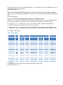
4.15 Actual airflow / pressure output signals
A 0-10V signal representing the actual airflow or the actual pressure delivered by one of the selected fans
with a linear relation is a standard feature. The output signals are located between terminals OUT1/OUT2
and GND on the TAC4 DG circuit.
Default setup: OUT1 = airflow fan 1 (supply fan) and OUT2 = pressure fan 1 (supply fan).
Table link between 0-10V signal and actual pressure or airflow value. (Linear equation):
Maxi-series
maxi 802
maxi 1202
maxi 2002
maxi 3002
maxi 4002
maxi 5002
maxi 6002
528007180 52800718020 528007200
Pressure (Pa)
0V
0
0
0
10 V
675
780
1090
Airflow (m3/h)
0V
0
0
0
10 V
960
1450
2400
528007210
528007220
528007230
528007240
0
1060
0
1090
0
1140
0
1075
0
3600
0
2400 (*)
0
3000 (*)
0
3600 (*)
(*) Airflow per fan, Airflow x 2 to obtain actual total airflow.
Maxi flat-series
maxi flat 450
Pressure (Pa)
0V
10 V
Airflow (m3/h)
0V
10 V
maxi flat 600
maxi flat 1000
maxi flat 1600
maxi flat 2000
0
650
0
870
0
800
0
930
0
1060
0
540
0
720
0
1200
0
1920
0
2400
23
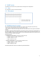
Via the ‘advanced setup’ it is possible to connect any of these 2 OUT signals to the airflow or pressure
value of any fans.
Wiring diagram of outputs signals:
Default: OUT1 = actual airflow of fan 1 (supply)
Default: OUT2 = actual pressure of fan 1 (supply)
5 Configuration and use
5.1
Principles of GRC TAC4
The GRC configuration is made with the touch screen. To preserve the display it is
strongly recommended not to use a pointed object to navigate through the different
screens.
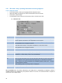
In the home screen, select your language with the dropdown menu. 4 languages are available: English,
French, Dutch and German. To access the various menus, open the sidebar by clicking on the arrow at
the bottom left of the screen.
The information is structured in 6 different menus:
• Control menu: for Fan control: start/stop, assignment selection. See § 5.2.1.2 or 5.2.2.2, 5.2.3.2
according to working mode.
• Visualization menu: provides information about the selected (current state, unit configuration,...).
All information in this menu is read-only. It is not possible via these screens to change the
configuration.
• Setup menu: choice and configuration of the basic parameters of the selected unit (see § 5.2).
• Advanced Setup: configuration of ‘advanced’ parameters. It is only recommended to qualified
personnel to change parameters in this menu. More information: see advanced setup
documentation.
• Network: configuration and visualization of a network of several TAC4 units (see § 5.4).
• Timetable: configuration of the timetable (see § 5.3).
It is possible to protect these different menus by access codes. The configuration is made via the
advanced setup.
24
How to operate:
• Select the white cells (editable) to change the value. A numeric keypad is automatically displayed
to enter the appropriate value. Press "Enter" to confirm.
• If entered value is not valid (out of range), it is ignored and the previous value is saved.
• Press on drop-down menus to see the different possible options. Press on chosen option you
want to select.
• Shaded boxes are not editable.
5.2
Setup and fan control
Fans can be ‘managed’ in 3 different control modes: CA, LS or CPs. A fourth mode (OFF) allows forcing a
shutdown of the unit. For more information, refer to the § 4.3.
5.2.1
CA mode: setup, operating instructions and wiring diagrams
5.2.1.1 Setup CA mode
To start the setup:
• In the home screen, select your language with the dropdown menu.
• Open the sidebar by clicking on the arrow at the bottom left of the screen.
• In the menu, select "Setup"
• In the dropdown menu at the top of the screen, select "current mode: CA."
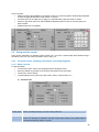
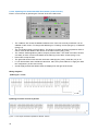
a) «General» tab
Working mode
Choice of working mode (CA, LS, CPs or OFF): select CA
%Ex/Su
Enter of ratio (%) of between exhaust (fans F3, F4) and supply (fans F1, F2) airflows
Airflow 1
Enter supply airflow 1 (enabled if contact between terminals K1 and + 12V closed on TAC4 DG
circuit, or if ‘fan1logo’ is selected in the GRC TAC4 control screen). The exhaust airflow is
calculated automatically based on %Ex/Su
25
Airflow 2
Enter supply airflow 2 (enabled if contact between terminals K2 and + 12V closed on TAC4 DG
circuit, or if ‘fan2logo’ is selected in the GRC TAC4 control screen). The exhaust airflow is
calculated automatically based on %Ex/Su
Airflow 3
Enter supply airflow 3 (enabled if contact between terminals K3 and + 12V closed on TAC4 DG
circuit, or if ‘fan3logo’ is selected in the GRC TAC4 control screen). The exhaust airflow is
calculated automatically based on %Ex/Su
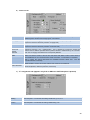
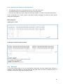
b) «Alarm Pa» tab
Pressure alarm ?
Pressure alarm is optional. To activate pressure alarm press the dark green diode
(disabled),when diode becomes bright green it is enabled.
dP supply
Setup Pa Alarm on supply side. Enter pressure increment (corresponding to the airflow
required to reach the reference pressure on supply side)
dP exhaust
Setup Pa Alarm on exhaust side. Enter pressure increment (corresponding to the airflow
required to reach the reference pressure on exhaust side)
Pa ref init :
Reference pressure ( Paref ) determination. Paref is defined by running the supply and
exhaust fans at airflows specified below (exhaust airflow is determined by the "%Ex/Su"
ratio. Paref for supply and exhaust are consequently different.
Supply
Exhaust
Start
Make sure that the panels of the unit are well closed, with filters in place. Press "Start" to
start initialization of Paref (optional if been made previously). A confirmation is requested.
After 1 minute, the control memorizes the calculated pressure values Paref
requested airflow is reached)
Alarm threshold
once the
While initializing exhaust and supply airflows and pressures are displayed.
Indicates the airflow rates and pressures that will be used to calculate the Pa alarm
threshold (airflows, reference pressure, increments).
c) «T° assignment» tab (appears only if NV or KWout or SAT BA option is present)
26
Heating
Enter set point T° for exhaust air heating. Details see § 4.10, 4.11
Cooling
Enter set point T° for exhaust air cooling. Details see § 4.12.
5.2.1.2 Operating CA mode with GRC TAC4 master (‘Control’ screen)
Enter in control screen by pressing the "Control" knob of the side menu.
•
•
•
•
•
•
The "Address" box shows the Modbus address of the TAC4 unit currently monitored. It is not
editable via this screen. To change this address go to "Viewing" screen (see § 5.5) or "Network"
(see § 5.4).
The "Pa" diode signals a pressure alarm. The diode is red when at least one pressure alarm is
active. Press to see details of the alarms on the alarm screen (see § 5.5.2)
The "Alarms" diode signals any alarm except a pressure alarm. The diode is red when at least
one alarm is active. Press to see details of the alarm(s) on the alarm screen (see § 5.5.2)
Press OFF to stop the fans.
The 3 supply constant airflows configured (airflow1, airflow2 and airflow3) are selected by
pressing the corresponding fan1/2/3 logo, on the screen. The active selection is shown by the
LED located below.
Actual supply and exhaust airflow rates are displayed on the right of the screen.
5.2.1.3 Operating CA mode with TAC4 DG master
One of the 3 assignment constant airflows (airflow1, airflow 2 and airflow 3) is selected using the
K1/K2/K3 terminals on TAC4 DG. The selection made is highlighted by the corresponding LED of the
‘CONTROL’ screen on the RC TAC4). The exhaust airflow is equal to (%EXT/PUL) of the supply airflow.
Wiring diagrams
a) Wiring 1 circuit to 3 external contacts
3
K1 closed airflow m h K1
3
K2 closed airflow m h K2
3
K3 closed airflow m h K3
K1/K2/K3 open soft stop
Caution K1/K2/K3: Use gold-plated contacts only.
27
b) Wiring several circuits to 3 external contacts
K1 closed Airflow 1
K2 closed Airflow 2
K3 closed Airflow 3
K1/K2/K3 open soft stop
Caution K1/K2/K3: Use gold-plated contacts only.
5.2.2
LS mode: setup, operating instructions and wiring diagrams
5.2.2.1 Setup LS mode
To start the setup:
• In the home screen, select your language with the dropdown menu.
• Open the sidebar by clicking on the arrow at the bottom left of the screen.
• In the menu, select "Setup"
• In the dropdown menu at the top of the screen, select "current mode: LS".
a) «General» tab
Working mode
Choice of working mode (CA, LS, CPs or OFF): select LS
V min
V max
Flow ≡ Vmin
Flow ≡ Vmax
Stop fans if
V<Vlow ?
Vlow
Stop fans if
V>Vhigh?
Vhigh
Enter Vmin for LS link (minimum voltage)
Enter Vmax for LS link (maximum voltage)
Enter airflow rate corresponding to Vmin
Enter airflow rate corresponding to Vmax (can be < or > to « flow ≡ Vmin »).
Possibility to stop the fans automatically if 0-10V signal < Vlow. Press led to turn this feature on
(the led becomes green).
Appears only if feature is enabled. Enter threshold value Vlow (Vlow < Vmin).
Possibility to stop the fans automatically if 0-10V signal > Vhigh. Press led to turn this feature
on (the led becomes green).
Appears only if feature is enabled. Enter threshold value Vhigh (Vhigh > Vmax).
%Exhaust
/Sup
Select airflow ratio between exhaust airflow (fans F3,F4) and supply airflow (fans F1,F2)
% on K3
Enter multiplier (%) of the LS link when contact between terminals + 12V and K3 on TAC4 DG
circuit is closed, or if in position "smallest fan" on the control screen.
0-10V on K3
In this configuration, the exhaust airflow is independent from the supply airflow The airflow ratio
(%Exhaust/Sup) is replaced by another 0-10V signal connected between GND and K3. The
same LS link as above (Vmin, Vmax) is used to determine the exhaust airflow.
28
b)
«Alarm Pa» tab
Pressure alarm ?
Pressure alarm is optional. To activate pressure alarm press the dark green diode
(disabled),when diode becomes bright green it is enabled.
dP supply
Setup Pa Alarm on supply side. Enter pressure increment (corresponding to the airflow
required to reach the reference pressure on supply side)
dP exhaust
Setup Pa Alarm on exhaust side. Enter pressure increment (corresponding to the airflow
required to reach the reference pressure on exhaust side)
Pa ref init:
Reference pressure ( Paref ) determination. Paref is defined by running the supply and
exhaust fans at airflows specified below (exhaust airflow is determined by the "%Ex/Su"
ratio. Paref for supply and exhaust are consequently different.
Supply
Exhaust
Start
Make sure that the panels of the unit are well closed, with filters in place. Press "Start" to
start initialization of Paref (optional if been made previously). A confirmation is requested.
After 1 minute, the control memorizes the calculated pressure values Paref
requested airflow is reached)
Alarm threshold
once the
While initializing exhaust and supply airflows and pressures are displayed.
Indicates the airflow rates and pressures that will be used to calculate the Pa alarm
threshold (airflows, reference pressure, increments).
c) «T° assignment» tab (appears only if NV or KWout or SAT BA option is present)
Heating
Enter set point T° for exhaust air heating. Details see § 4.10, 3.11
Cooling
Enter set point T° for exhaust air cooling. Details see § 4.12.
29
5.2.2.2 Operating LS mode with GRC TAC4 master (‘Control’ screen)
Enter in control screen by pressing the "Control" knob of the side menu.
The supply airflow assignment is function of a 0-10V signal connected to input K2 of the TAC4 DG circuit
(linear link). The exhaust airflow is linked to the supply airflow by a user defined value (%EXT/PUL). If
option «0-10V on K3 » is activated the assigned exhaust airflow is determined by a separate 0-10V signal
connected to K3.
•
•
•
•
•
•
•
The "Address" box shows the Modbus address of the TAC4 unit currently monitored. It is not
editable via this screen. To change this address go to "Viewing" screen (see § 5.5) or "Network"
(see § 5.4).
The "Pa" diode signals a pressure alarm. The diode is red when at least one pressure alarm is
active. Press to see details of the alarms on the alarm screen (see § 5.5.2)
The "Alarms" diode signals any alarm except a pressure alarm. The diode is red when at least
one alarm is active. Press to see details of the alarm(s) on the alarm screen (see § 5.5.2)
Press OFF to stop the fans.
The green led shows which selection has been made (big fan (100%), small fan (x%) or off.
If “%on K3 has been set to a different value than 100%, then press “little fan” to apply the “little
fan” assignment. (In this case x=50%)
Actual supply and exhaust airflow rates are displayed on the right of the screen.
a) Wiring to 1 circuit
(*)
(*)
b) Wiring to several circuits connected in parallel
(*)
(*) K2 0-10V signal, maximum impedance allowed: 1500 Ω
30
5.2.2.3 Operating LS mode with TAC4 DG master
The assignment value for the supply constant airflow is a function of a 0-10V signal connected to terminals
K2 of the TAC4 DG circuit. The link between voltage and airflow is linear. The exhaust constant airflow is
equal to %EXT/PUL of the supply airflow (except if 2 separate 0-10V signals are used to determine
exhaust and supply constant airflows, see advanced setup).
• Starting/stopping the fans is carried out with entry K1 on the TAC4 DG circuit.
• The pressure sensor is connected to entry K2 of the TAC4 DG circuit.
• The K3 entry of the TAC4 DG can be used to activate the pre-set multiplier (% on K3.
In this configuration, the ‘control’ screen of the GRC is always accessible, but does not allow airflow
assignment modifications.
Wiring diagrams
a) Wiring to 1 circuit
(*)
b) Wiring to several circuits in parallel
(*)
(*)
K1 closed soft start
K1 open softstop
K2 0-10V signal, maximum impedance allowed: 1500 Ω
K1+K3 closed % on K3 activated
K3 open % on K3 inactive
Caution: use gold-plated contacts only.
31
5.2.3
CPs mode: setup, operating instructions and wiring diagrams
5.2.3.1 Setup CPs mode
•
•
•
•
In the home screen, select your language with the dropdown menu.
Open the sidebar by clicking on the arrow at the bottom left of the screen.
In the menu, select "Setup"
in the dropdown menu at the top of the screen, select "current mode: CPs".
a) «General» tab
Working mode
Select working mode (CA, LS, CPs or OFF): select CPs
Cps on
« Supply » or « Exhaust » or « Supply and Exhaust ». Select in which airflow the pressure
sensor is placed. See below for more explanations on the 3 options.
%Exhaust/Supply
Enter airflow ratio between exhaust airflow (fans F3,F4) and supply airflow (fans F1,F2)
% on K3
Not applicable if CPs on supply and exhaust.
Enter multiplier (%) of the CPs assignment when contact between terminals + 12V and K3 on
TAC4 DG circuit is closed, or if in position "smallest fan" on the control screen.
Not applicable if CPs on supply and exhaust.
Init pressure
« via flow rate » or « manually ». Specify method to determine reference pressure.
If Init pressure VIA AIRFLOW: TAC4 DG automatically computes set point pressure value
xx,x V
Last registered pressure set point (0.0 if never made). Non-editable in this type of
initialization. To edit it directly, switch to manual initialization.
xxxx m³h
Enter (nominal) airflow at which the pressure set point must be determined.
Start
Make sure that the panels of the unit are well closed, with filters in place. Press "Start" to
start initialization of Paref (optional if been made previously). A confirmation is requested.
After 1 minute, the control memorizes the calculated pressure values Paref
requested airflow is reached)
once the
While initializing airflow and Voltage values are displayed..
If MANUAL Init pressure : enter pressure set point directly
xx,x V
Enter pressure setpoint value
CPs on SUPPLY air: The airflow delivered by the supply fans is automatically modulated to obtain a
constant pressure as measured by the pressure sensor in the duct. The exhaust airflow is equals to
%EXT/PUL of the supply airflow.
32
CPs on EXHAUST air: The airflow delivered by the exhaust fans is automatically modulated to obtain a
constant pressure as measured by the pressure sensor in the duct. The supply airflow is equals to
1/(%EXT/PUL) of the exhaust airflow.
CPs on SUPLY + EXHAUST air: the supply fan’s airflow is automatically modulated to obtain a constant
pressure as it is measured by a pressure sensor connected to K2. And the exhaust t fan’s airflow is
automatically modulated to obtain a constant pressure as it is measured by a pressure sensor connected
to K3.
b) «Alarm Pa» tab
The unit being programmed to maintain a constant pressure, the pressure alarm based
on the calculation of the working point is not applicable. However, it is possible to connect
an external alarm between the IN2 and + 12V input terminals.
c) «T° assignment» tab (appears only if NV or KWout or SAT BA option is present)
Heating
Enter set point T° for exhaust air heating. Details see § 4.10, 4.11
Cooling
Enter set point T° for exhaust air cooling. Details see § 4.12.
33
5.2.3.2 Operating CPs mode with GRC TAC4 master (control screen)
Enter in control screen by pressing the "Control" knob of the side menu.
•
•
•
•
•
•
•
The "Address" box shows the Modbus address of the TAC4 unit currently monitored. It is not
editable via this screen. To change this address go to "Viewing" screen (see § 5.5) or "Network"
(see § 5.4).
The "Pa" diode signals a pressure alarm. The diode is red when at least one pressure alarm is
active. Press to see details of the alarms on the alarm screen (see § 5.5.2)
The "Alarms" diode signals any alarm except a pressure alarm. The diode is red when at least
one alarm is active. Press to see details of the alarm(s) on the alarm screen (see § 5.5.2)
Press OFF to stop the fans.
The green led shows which selection has been made (big fan (100%), small fan (x%) or off.
If “%on K3 has been set to a different value than 100%, then press “little fan” to apply the “little
fan” assignment. (in this case x=50%)
Actual supply and exhaust airflow rates are displayed on the right of the screen.
Wiring diagrams
a) Wiring to 1 circuit
(*)
b) Wiring to several circuits in parallel
(*)
(*) K2 0-10V signal, maximum impedance allowed: 1500 Ω
34
5.2.3.3 Operating CPs mode with TAC4 DG master
• The start/stop of the fans is controlled by entry K1 of the TAC4 DG circuit.
• The pressure sensor is connected to entry K2 of the TAC4 DG circuit.
• K3 on the TAC4 DG circuit can be used to activate the multiplier ‘% on K3’ on the airflow assignment
In this configuration, the ‘control’ screen of the GRC is always accessible, but does not allow airflow
assignment modifications.
Wiring diagrams
a) Wiring to 1 circuit
(*)
b) Wiring to several circuits in parallel
(*)
(*)
K1 closed soft start
K1 open softstop
K2 0-10V signal, maximum impedance allowed: 1500 Ω
K1+K3 closed % on K3 activated
K3 open % on K3 inactive
Caution: use gold-plated contacts only s.
5.2.4
Mode OFF
Is not a real working mode, it is a way to temporarily shortcut the TAC4 DG master setup. It allows, if
working in TAC4 DG master, to stop the fans with the GRC TAC4. But then to restart the fans it is
required to choose one of the other 3 working modes.
35
5.3
Time slots schedules
A GRC TAC4 allows changing working modes between time slots. (For instance LS during the day and
CA at night). The time slot programming is only enabled when the regulation is set to "automatic".
5.3.1
«Setup» tab
The timeslot programming is done in CA mode by entering specific airflows for each time slot (TS) and for
LS and CPS modes by entering a multiplier which will then be applied to a basic setup. So, if chosen,
enter first the LS and CPs ‘basic’ setup. If CA is chosen go to next step.
The "Setup" tab to configure LS or CPs basic setup:
• enter the date and time
• If LS mode:
o press the "LS" button
o Enter the Vmin and Vmax values and corresponding airflow rates.
o Specify if the fan must stop above or / and below a certain voltage value.
o If Yes please specify Vlow and/or Vhigh
o "0 - 10V on K3" allows controlling the exhaust airflow rate via a second signal connected on
K3.
•
36
If CPs mode:
o Specify on which side pressure is kept constant (exhaust and/or) supply side
o Specify how reference pressure is initialized (via nominal airflow or pressure value)
o If via nominal airflow enter airflow rate value and press ‘start’ to start initialization
o If via pressure value, enter Volt value corresponding to the pressure assignment value.
5.3.2
«Week planner» tab
The "timeslots" feature allows configuration of complex timeslots. Six timeslots per day, thus 42 different
configurations. For each time slot the working mode and the assignment must be configured.
Configuring a time slot:
• Press on one of the boxes on the screen.
• Indicate the start time of the time slot.
• Select the working mode.
• Enter ‘basic’ setup multiplier if LS or CPs, or constant airflows (exhaust and supply) if CA mode.
• Enter exhaust/supply ratio if LS or CPs mode
• Specify if by-pass is in automatic mode, open or closed.
• Specify T° set points in case of post-heating or post cooling (if option present)
5.3.3
«Year planner» tab (seasonally or yearly planner)
The season tab allows adapting the configuration according to the time of year and to option present or
not:
• Specify whether to disable the bypass (press button and introduce period)
• specify whether to disable the post-heating (press button and introduce period)
• specify whether to disable the cooling coil (press button and introduce period)
5.4
Network management
One GRC TAC4 can be linked to several units in parallel.
5.4.1
General
Modbus communication allows interaction between several TAC4 regulations. In a Modbus network, each
unit is referenced by its Modbus address (a number from 1 to 247). It is forbidden to have two units with
the same Modbus address on one network.
Default TAC4 CB Modbus address is 1.
37
5.4.2
Network Visualization
Network View tab allows changing the communication address on the network, as well as to see a list of
selected units on the network and programmed by the installer. This list of maximum five units is a
reminder for the user to easily identify the units. It is the responsibility of the installer to be certain that this
list actually corresponds to the actual network put in place. GRC TAC4 cannot detect mismatches of this
type.
5.4.3
Edit a network
5.4.3.1 Screen description
The "Edit" tab allows:
• to modify an address of a TAC4 unit:
o Enter current address of the TAC4 unit in the "From"field
o Enter new address in the "to" press field
o Press "Apply" button to carry out change
• to identify each unit on the network by name and corresponding address ( only 5 names can be
displayed at the same time, but each unit (up to 247) can have his own name)
5.4.3.2 Method
Each CB TAC4 is factory programmed with a Modbus address of ‘1’. To create a network it is therefore
necessary to change this address before connecting the different units on the same network.
To do this, follow the following sequence:
• ensure that all units on the network are powered of or disconnected from the network
• Turn on (or connect to network) the first unit, and enter an address different than ‘1’.
• Enter address and identification name of unit in the list
• turn on (or connect to network) the second unit, and enter a different address than ‘1’ or than the
first address entered
• Etc…
• It is advised to keep the ‘1’ address for the last unit connected.
38
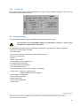
5.5
Visualization
The display screens allow accessing all the useful information. These screens are "read only". They do
not allow editing or setup changes.
In the case that several units are supervised by the same GRC (network), it is interesting to easily
navigate from one unit to another to get a quick overview of the different units installed. To do this it is
possible to modify the current Modbus address.
If an non-existent address is entered, the GRC produces an error message. This message indicates that
no unit responds to the specified address. This will have no influence on the other units connected to the
network. To solve the problem, enter a valid address. More information in the section "Network
management" (§ 5.4).
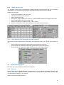
5.5.1
«Synoptic» tab
The "Synoptic" tab returns a general overview of the actual ‘on line’ values of one specific unit. It
automatically adapts depending on the selected setup and options.
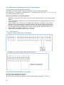
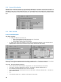
5.5.1.1 General information
1
2
7
6
5
3
4
1. MODBUS address of CB4 TAC4 DG circuit. This address field is editable in each “visualization”
screens. To manage a network of several installations, see "Network" screens (see § 5.4).
2. Actual supply airflow rate
3. Indoor inlet air T° (T2, white wire sensor)
4. Diode representing all alarms of the unit selected, except for the pressure alarms. The diode is
red when an alarm is active. Press on diode to be automatically directed to the alarm screen (see
§ 5.5.2).
5. Diode representing pressure alarms. The diode is red when a pressure alarm is active. Press
diode to be automatically directed to the pressure alarm screen (see § 5.5.2)
6. Outdoor air T° (T1, black wire sensor)
7. Actual exhaust airflow rate and supply air T° (T3, blue wire sensor)
39
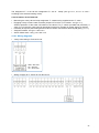
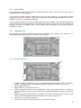
5.5.1.2 Air «Flows» tab
Collared arrows provide a schematic and intuitive representation of the air flows in the unit.
Exhaust and supply airflows with heat
exchange between flows.
Exhaust and supply airflows without heat
exchange between flows (bypass open,
free cooling)
Exhaust airflow only (supply fans
stopped)
Supply airflow only (exhaust fan
stopped)
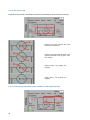
5.5.1.3 Post heating information (if NV or KWout or BA+ option present)
40
The upper right corner of the synoptic provides supply air information. This can be displayed in 4 different
ways:
1. No post-heating
2. NV post-heating inside unit (hot water coil)
2
1
1. Exhaust flow air T°(T5, green wire sensor installed by
customer in the ducting).
2. 3-way valve opening control signal.
3. KWout post-heating inside unit (electrical coil)
1. Exhaust flow air T°(T5, green wire sensor installed by
customer in the ducting).
2. Electrical coil’s used capacity (expressed in %) .
2
1
4. View BA+, BA-, KWext settings, if controlled by SAT TAC4 BA/KW option (see Installation and user’s
manual for additional information)
41
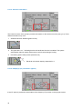
5.5.1.4 Anti-frost information
The lower left corner of the synoptic provides information on the anti-frost function (see § 4.9). Three
different situations may occur:
1. Antifreeze function disabled (green led ‘off’)
2. The green led is ‘on’ : indicating that the built antifreeze function is enabled. The system
automatically reduces supply airflows rate to avoid heat exchanger frosting.
3. Pre-heating option KWin present (electrical coil)
1
1. Electrical coils actual capacity expressed in %.
5.5.1.5 Damper(s) (CT) information (option)
If the CT option is present the actual status of the damper (CT) is shown in the synoptic screen.
42
Dampers closed
Dampers ‘opening’ (30 seconds waiting time)
Dampers open
5.5.2
«Alarms» tab
The "Alarms" tab gathers the status of each different alarm available. The corresponding led turns red
once the alarm is activated. By pressing the led the GRC displays the details of the alarm. A message
describes the alarm and suggests appropriate action to solve the problem.
An "Alarms Reset " button allows restarting the system, this should only be done
when after having carefully read the alarm message, identified the cause of the alarm
and solved the issue.
5.5.3
•
•
•
•
«Setup» tab
The "Setup" tab shows the actual setup assignment of the unit on the supply side.
If a post heating system is installed and configured, the supply T° set point is also displayed.
By pressing ‘View setup’, the detailed parameters of the selected working mode are displayed.
If a pressure alarm has been configured, the parameters (threshold values) are also displayed.
43
5.5.4
«Flows» tab
The "Flows" tab gives detailed information about actual airflows and pressures per fan (one or two fan(s)
by flows, depending on the type of unit installed) and the actual temperatures measured.
5.5.5
«I/O» tab
The "Flows" tab gives detailed information about actual airflows and pressures per fan (one or two fan(s)
by flows, depending on the type of unit installed) and the actual temperatures measured.
44
5.5.6
«Config» tab
The "Config" tab shows the factory setting data.. Unit type, options installed, language chosen (can be
edited here) and the software version.
5.6
Advanced setup
Using this feature requires a good knowledge of the TAC4 DG control system.
The functions of the ADVANCED SETUP are described in annexes 1 and 2 of the
installation and maintenance instructions.
The advanced configuration allows modifying the parameters not present in the basic configuration.
- Stop fans if pressure alarm activated
- Fans start torque
- Prevent stop of the fans (deactivation of the softstop function)
- Fire alarm configuration
- Bypass T°
- Airflow if bypass open
- Force bypass opening whatever the T°
- AF (anti-freeze) configuration
- NV speed (option if NV installed)
- OUT1 and OUT2 definition
- In LS mode: stop of the fans if Vin < and/or > set value(s)
- In CPs mode: - positive or negative logical
- reaction speed of the CPs algorithm
- Post-ventilation configuration
- Fan run time configuration
- Display alarms only
- Access code configuration
- Factory reset
As of June 3rd 2013
_____________________________________________________________________________________________
Although we put a lot of care in the making of our documentation, we cannot be held responsible for any error and/or
omissions that could have slipped in.
45