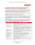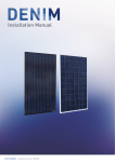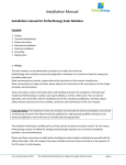
1
Installation and Operating Instructions
Manufactured with
sustainable energy
www.heckert-solar.com
01.03.2014
Installation and Operating Instructions
These instructions are intended for the use of dealers and fitters engaged in the design, installation and operation of
photovoltaic (PV) systems consisting of high-performance, polycrystalline or monocrystalline solar modules from the range
supplied by Heckert Solar AG. They are designed to ensure that the PV system concerned delivers optimum performance
throughout its working life. All Heckert Solar-brand modules are manufactured in Germany, and are among the highestquality PV units of their type to be found anywhere in the world. They are characterised by extremely high standards of
workmanship and long-term stability.
Heckert Solar-brand modules may only be installed by properly-qualified specialists. Please observe the relevant norms and
standards applying to photovoltaic installations, including – for example – VDE regulations, DIN standard specifications,
VDEW guidelines and TAB (Technical Advisory Authority) standards (or local equivalent) of the corresponding mains network
operator, along with the relevant health and safety and accident-prevention measures. Failure to observe these stipulations
may result in grave personal injury or serious damage to systems and equipment. The indications contained in these
installation and operating instructions are based on current German legislation and industrial standards.
The recommendations that follow are designed to help ensure the smooth, trouble-free installation of your Heckert Solarbrand modules. Please seek expert advice in the event of individual queries, and in order to ensure that the roof
specifications are observed.
Keep these instructions in a safe place, along with all the other documents supplied with the system.
These installation and operating instructions conform to the stipulations of TÜV Rhineland regarding safety certificate IEC
61730, part 1.
Overview
1.
2.
3.
4.
5.
6.
7.
8.
9.
Hazard warnings and safety instructions
General information regarding PV systems
Delivery and handling of modules
Information regarding the module
Module installation
Connection and hook-up of modules
Return and recycling
Product/performance guarantee
Exclusion of liability
2
1. Hazard warnings and safety instructions
Solar modules generate electricity as soon as they are exposed to light. Voltage of 30 volts and more constitutes a danger in
the event of physical contact. The connection, in series or parallel, of various modules increases the voltage and current
accordingly. Note that the arrangement in series of more than two solar modules can result in voltages that are potentially
fatal.
CAUTION: Danger of fatal electric shock!
The plug-in contacts are fully insulated to prevent them being touched. You should however take the following precautions
when handling the solar modules:
•
•
•
•
•
Do not insert electrically conductive items into the pin-type or sleeve connectors.
Do not install solar modules or wire conduits if their pin-type/sleeve connectors are wet.
All work on wires and cables must be carried out with the utmost care and attention.
Beware of the high contact-voltages present in the power inverter, even when it is in an idle state.
Exercise great care when carrying out work of any kind on the power inverter and/or its wiring system.
Heckert Solar-brand modules are designed for employment as Class A applications: Systems with dangerous output (>
240W), designed for generally unrestricted access, with the presence of hazardous voltages (IEC 61730: > 50V DC;
EN61730: > 120V DC). Modules compatible with safety standards EN IEC 61730-1 and 61730-2, qualified within these
classes of application correspond with the requirements of Protection Class II.
CAUTION: Danger of fatal injury due to arcing!
The opening of a completed live circuit (e.g. disconnection of the DC lead from the power inverter while under load) can
result in fatal injury due to arcing.
•
NEVER disconnect the solar generator from the power inverter while it is still connected to the network!
2. General information regarding PV systems
Alignment
The solar module should be positioned as near as possible due south, in order to ensure optimum energy yield. You can also
align the solar module according to the position of the sun. The module should be inclined at an angle of at least 15°. The
optimum angle of inclination can be calculated using the following formula:
Angle of inclination = degree of latitude of installation site -20°.
Place of installation
The planned site of installation should be as free as possible of obstacles that are likely to create shade (e.g. other buildings,
trees, chimneys, dormer windows, TV aerials, satellite dishes, overhead power lines, etc.), as these items can significantly
reduce the performance of solar modules. Even partial shadows can result in considerable reductions in output. A module is
considered shade-free if sunlight can fall on its entire surface all year round, with at least a minimal amount of light able to
fall on it unhindered even at unfavourable, less-sunny times of year.
Rear ventilation
The output of solar modules is considerably reduced as they heat up. This applies in particular to our Black Edition units,
which – as the name implies – come with a black foil covering on the rear and a black frame. Rear-face ventilation helps
prevent these performance-reducing build-ups of heat. You should therefore ensure, when installing the unit, that there is a
sufficiently large gap at the back for the purposes of ventilation. Ensure also that there are no nearby items – such as
skylights, glazed roofs, etc. – that are likely to spoil the “chimney-draught” effect that this system of ventilation relies on.
3
Winter
The solar modules should be positioned in such a manner that as little snow as possible falls on them during winter. A short
distance with respect to the eaves and a roof inclination of <20° are both likely to lead to accumulations of snow on the
bottom row of modules. Check the openings in the hollow profile sections of the module frame, and keep the corners free of
dirt, so that condensation water can drain off freely.
Cleaning/maintenance
With a sufficient inclination of the modules (>15°), cleaning is generally not required (self-cleaning by rain/snow). However,
ambient conditions can have a strong influence on the soiling of modules, which should be checked at yearly intervals for
accumulations of dirt. If the modules do become soiled, they should be cleaned when cool (e.g. during the early morning),
using plenty of lukewarm water and a soft scouring pad. DO NOT use sharp, abrasive or pointed implements of any kind to
clean the surface. Modules with AR glass should be cleaned by using plenty of lukewarm, demineralised water and clean,
lint-free cotton, microfiber or paper towels. Please note that sudden, extreme changes in temperature can create tension
strain in the glass, resulting in irreparable damage to the module. Greasy or oily residues can be removed with alcohol or a
mixture of alcohol and water. The following should all be avoided: strong acids, caustic solutions, petrol- based cleaners,
steam or heat- based cleaners, cleaning agents containing silicon oils, fluorides or waxes, polishes, alkaline cleaners,
cleaners, cleaners containing scouring agents and high pressure cleaners. All methods and means that replace Na ions in
the glass surface are unsuitable for the cleaning of glass. All abrasive cleaning agents and utensils are equally unsuitable for
this purpose.
CAUTION: When carrying out cleaning and maintenance work, take care to ensure that the earth (ground)
connection is not broken or damaged.
3. Delivery and handling of modules
Check the delivery on arrival to ensure that all items are complete and undamaged. Heckert Solar will only recognise transit
damage if it has been recorded on the driver’s delivery note and reported immediately in writing. Our modules are normally
delivered in an upright position on a non-returnable pallet, so that one person can remove the individual units without risk
of back injury. The modules should be handled with great care. Laminated items supplied without a module frame are
particularly sensitive to impact damage. Unpacking, transport and interim storage should therefore be carried out with
utmost care. Leave the modules in their packaging until you intend to install them. DO NOT stack one pallet on top of
another.
CAUTION: Carefully follow the unpacking instructions printed on the packaging material. DO NOT remove the
rear retaining tape at this stage.
CAUTION: Handle the modules with great care!
•
•
•
•
•
Always lift and carry the modules using both hands. Do not use the connection box or cable to lift the module; do
not pull on the connection cable at any time. (See Fig. 5 on page 9).
Do not expose the modules to extreme vibrations. Lower the modules gently when placing them on a hard surface.
Do not stand the modules on their corners. When stacking one module on top of another, always place a layer of
protective material in between. DO NOT place objects of any kind on top of the modules. NEVER stand on the
modules. Do not drop the modules; Do not handle them with hard or pointed implements of any kind.
The modules should be connected with great care, without using force. Keep all electrical contacts clean and dry.
If you need to store the modules temporarily, ensure that they are kept in a dry, well-ventilated room.
In order to keep a proper record of fitting, you should note down the serial number on the system layout plan kept
at the place of installation.
CAUTION: Carefully follow the special information on the handling of modules with AR glass
The surface of the module has a resistance to mechanical or chemical influences comparable with non-coated modules.
Therefore they should be treated with the same degree of carefulness. Due to the special reflective properties slight
contamination is, however, better visible. In particular, greases and oils in small amounts are already visible and can
influence transmission. In order to avoid these marks, the modules should be handled with care already with unpacking and
assembly and the surface of the modules should be touched exclusively using clean gloves.
4
4. Information regarding the module
Certification, Performance data
Heckert Solar AG is one of the few suppliers in the sector that still produces absolutely all of its own-brand modules in
Germany, placing great value on the certification of its product quality. For details of the performance specifications of our
modules please refer to the data sheets of the corresponding series.
Usage
Please take the following factors carefully into account when using our modules:
•
•
•
•
•
•
•
•
Do not immerse the solar module in liquids or fluids of any kind.
The solar module is not compatible with seawater (recommended separation 500 metres from the sea).
The module should not be exposed to extreme chemical contamination (e.g. harmful emissions from industrial
premises).
Do not use lenses or mirrors to concentrate the prevailing light (danger of overheating).
Avoid damaging the module through hard-metal and diamond-edged objects.
Protect solar modules from voltage surges (such as those produced by battery chargers, generators, etc.). If in
doubt, please contact your specialist dealer.
When connecting solar modules to storage batteries, be sure to observe the safety precautions specified by the
battery manufacturer.
Keep children away from the solar modules.
The closer the site of installation is to the equator, the more likely it becomes that the currents and voltages present can
exceed those generated by a PV module under standard test conditions. You should therefore multiply the module’s
indicated Isc and Uos values by a factor of 1.25, when determining the voltage ratings of components, current ratings of
conductors and sizes of fuse for connection at the PV-module outputs.
The maximum measured rating for overcurrent protection (reverse-current resistance) is 15A.
5. Module installation
Heckert Solar-brand modules are available in standard configuration, with aluminium frame; as laminated units without a
frame (for rooftop and embedded roof-installation), and with SOLRIF® frames for embedded roof-installation using the
SOLRIF® system. The availability of our own fitting system, along with those supplied by our partners Schweizer Metallbau
(SOLRIF® in-roof) and Schletter, ensures that we can handle virtually any rooftop installation, while also offering solutions
for certain building-frontage configurations. If you nevertheless intend to use a different system of installation, please be
sure to follow the instructions provided by the supplier concerned.
Instructions can be downloaded from the corresponding websites:
www.heckert-solar.com
www.schweizer-metallbau.ch
www.schletter.de
For Solrif®, the following requirements have been determined regarding water-tightness:
Roof pitch
10°
10° - 22°
>22°
<32°
>32°
<32°
Description
Minimum roof pitch for using Solrif®
Water-tight roof substructure required
Rain-proof roof substructure required
Underlay must be implemented to drain into the gutter
Roof renovation
No need to upgrade the old roof substructure (for using Solrif®)
The old roof substructure may need to be upgraded to be rain-proof
Fig. 1 application roof solution
5
General instructions for rooftop installation
Thanks to their high degree of stability, all of our standard-framed and laminated modules are suitable for both upright and
lengthwise installation. The modules can be clamped both by their long sides as well as by their short sides.
Please be sure to use the recommended clamping-points, as this is where the module’s maximum load-bearing capacity is
guaranteed. Additionally, when clamping on the short side of the module, the support distance of the used mounting rail
must not exceed 1m. Note also that the position of installation, snow load and type of roof (rafter or purlin-type) may
require the fitting of a set of crossbars.
Please consult with Heckert Solar before considering any other type of installation. The modules must not be subject to
strain of any kind during or after fitting. They are not designed to act as rigid connecting or reinforcing elements.
When installing laminated units, use special securing clamps designed for the purpose. We recommend the use of clamps
with a supporting surface of at least 15 mm and a minimum length of 70 mm (such as the 3 mm to 8 mm-wide Profi
end/centre clamps supplied by Schletter).
Grounding connection
- cable clamp
- bolt
- toothed washer
- nut
Fig. 2: Module dimensions 54-cells
Fig. 3: Clamping area 54-cells
Grounding
Module dimensions 60-cell s
Clamping area 60-cells
6
Fig. 4: Clamping on short side
Slip-prevention
Our module frames are supplied with drill-holes for the purposes of slip-prevention when installed in an inclined position,
and to make them easier to fit. Cylinder-head bolts with Allen-key sockets are inserted into these holes in the module frame.
The bolts are secured in place with a plain washer and nut, or a self-locking nut. The use of M 5 x10 VA bolts with
corresponding toothed lock-washer and nut is recommended for anti-slip purposes.
Module load capacity
Heckert Solar’s standard modules are certified by TÜV Rhineland to handle loads of up to 5400 Pa. SOLRIF®-type and
frameless solar modules have been tested at loads of up to 2400 Pa. The load capacity of the SOLRIF® modules can be
increased significantly by using additional mounting boards as support (please find more information on that in the
calculation tool “Prosolrif” by the company Schweizer).
CAUTION: Please note that the modules can only achieve their maximum load performance if they are
clamped in the specified clamping area and in compliance with all requirements.
Ensure that the maximum mechanical-load capacity is observed, paying particular attention to the load factors present at
the site of installation (such as those resulting from wind and snow, etc. See also DIN 1055-4/5). Note that the module may
buckle when subjected to excessive loads. Do not use any material that may result in the module being exposed to, and
therefore damaged by, sharp or pointed edges, or uneven structures. The snow load at base sk (measured in kN/m²) is
calculated using local levels of snowfall, the location of the building and its height above sea level. The likely wind load for
the site of the project should be estimated using a wind-zone chart that along with wind zones also takes into account local
conditions. A simplified procedure can be used to estimate prevailing wind-load when considering buildings of up to 25
metres in height. Depending on the height of the building, wind load is expressed as velocity pressure q, measured in
kN/m³. Wind-load charts and snowfall maps are available for download from websites such as:
http://de.wikipedia.org/wiki/Schneelast
http://de.wikipedia.org/wiki/Windlast
CAUTION: Please note that the specialist firm engaged to fit the system is solely responsible for the planning
and implementation of the project, and that a separate set of structural static calculations may have to be
drawn up in certain cases.
6. Connection and hook-up of modules
•
•
The modules are wired directly via the plug socket fitted to the connection box (Fig. 5):
Left-hand pin connector (+); right-hand pin connector (-)
All sockets used for this purpose must be of the authorised type supplied by Tyco. The use of plug-in connectors of
any other kind will void the warranty.
The unit is supplied ready-fitted with a 1.9 metre length of cable on the positive (left-hand) side. This cable is fitted
with the corresponding positive (+) and negative (-) sleeve connectors.
7
Pin connector (+)
Sleeve connector (-)
Pin connector (-)
Sleeve connector
Fig. 5: Connection box and cable
•
•
•
•
•
•
•
•
Modules can be connected to each other using this cable. The use of a single cable prevents a situation where plugin connections are constantly exposed to water.
DO NOT pull on the connection cable itself when unplugging it (see Fig. 6, page 8).
Pay attention to the requirements set out in DIN VDE 0298-3 regarding cable installation. In particular, note the
information on minimum bending radius, standards for the attachment of cables and on how to install them.
On the next module in sequence, the sleeve connector ((-) marked blue) is plugged in on the right-hand side (on
the box (-)).
This means that box (-) is always connected to cable (-).
The connections are internally configured to prevent their poles being reversed. A slight audible “click” indicates
that the plug-in connector has been properly inserted.
Plug-in connectors conform to protection class IP67, and sockets to IP65. Both components are therefore
permanently protected from dust.
Please pay careful attention to the instructions supplied by Tyco.
CAUTION: Each manipulation of the connection box can lead to a loss of warranty and may only be
undertaken by trained personnel!
CAUTION: Do not open the connection box or pull on the connection cable, and ensure that the connector is
properly plugged in all times, otherwise the protection rating can no longer be guaranteed (see Fig. 6).
CAUTION: Ensure that the cables are free of tension and properly crimped and connected to the plug!
Fig. 6: Do not pull on the cable.
If various strings are in use, we recommend sorting the modules by current-strength (IMPP). This will help ensure maximum
system output, as the weakest module determines the performance of the string as a whole.
CAUTION: DO NOT install modules that are damaged in any way!
8
Wiring layout
Each string requires two cables for connecting the solar generator to the power inverter. We recommend the use of special
solar cable conforming to standard IEC 60228, Class 5 for this purpose. It should have a minimum cross-section of 4 mm².
Cable losses should be <1%. The cross-section of the cable should be adjusted accordingly to minimise loss over larger
distances.
IMPORTANT: Ensure that pin- and sleeve-type connectors are correctly inserted into each other!
The strings (+ and - leads) are laid to the power inverter and connected to the DC inputs. The module plugs are marked
accordingly. The cable on the positive (+) plug of the module should be connected to the positive (+) input of the power
inverter. Proceed in a similar way with the negative (-) connection. The two strings (+ and -) should be laid together to
prevent the forming of conductor loops. The cable should run through the roof at a single point, if possible.
The solar cables must be fitted to the power inverter using only suitably-certified, compatible plug-in connectors. These
plug-in
connectors
are
secured
to
the
solar
cable
with
special
crimping
pliers.
It is vital to observe polarity of the strings when connecting them to the inverter. Please ensure not to interchange the +
and – cables. Use a multimeter/voltmeter to check the individual strings for correct polarity, and to verify their voltage,
before connecting them to the power inverter.
Installation and/or connection of the power inverter(s) should be carried out in accordance with the manufacturer’s
instructions (Fig. 7).
Max. Systemspannung
Max. system voltage
Tension système maxi
1000 VDC
Typ
Type
Type
NeMo®
NeMo®
NeMo®
NeMo®
NeMo®
NeMo®
54
54
54
54
54
54
P
P
P
P
P
P
195
200
205
210
215
225
Anzahl
Numbers
Nombre
Typ
Type
Type
Anzahl
Numbers
Nombre
Typ
Type
Type
26
26
26
25
25
24
NeMo® 54 P 230
NeMo® 54 P 235
24
24
NeMo®
NeMo®
NeMo®
NeMo®
NeMo®
NeMo®
Anzahl
Numbers
Nombre
60
60
60
60
60
60
P
P
P
P
P
P
240
245
250
255
260
265
23
22
22
22
22
22
Fig. 7: Number of modules for connection in series
IMPORTANT: Various string-lengths are possible, depending on module output and the type of power
inverter used (see Fig. 7)!
Parallel connection of PV modules
Please note that 15A fuse protection is required when connecting more than two strings of our modules in parallel. The
maximum reverse-current load is 15A. This may be exceeded in the event of a defect occurring, if more than two strings are
connected in parallel.
Electrical installation
Connection of the power inverter to the public grid MUST be carried out by a properly-authorised specialist firm. Pay
attention to the requirements set out in DIN VDE 0298-3 regarding cable installation.
CAUTION: High DC voltages are present even with small amounts of light-input. NEVER touch bare + or terminals while the system is in operation.
Earth (ground) connection
Requirements regarding lightning conductors and excess-voltage protection depend on local conditions. The firm carrying
out the installation work is responsible for ensuring that the module frames are correctly earthed (grounded) at the
positions indicated (see Fig. 8). An M4 screw is specified for earthing (grounding) purposes. This must be secured with a
split or toothed washer, in order to ensure that the Eloxal finish is properly penetrated.
9
If the building is already fitted with an external lightning conductor (or if one is to be installed), the PV system must be
suitably integrated to prevent direct lightning strikes. If power inverters without a transformer are used, they must be
suitably earthed (grounded) to provide personal protection and compensate for the lack of galvanic isolation. Applicable
local and national regulations are to be observed in this respect.
Identification of
earthing (grounding)
hole
Fig. 8: Identification of earthing (grounding) point NeMo®; Solrif®
When using SOLRIF® modules, the Schweizer specifications regarding equipotential bonding and lightning protection, which
are included in the fitting instructions, should be observed.
Fire prevention
The fitting of equipment to the roof may affect the fire safety of the building concerned, as incorrect installation can
suppose a fire hazard. Please observe local planning laws and building regulations. Heckert Solar-brand modules forming
part of a rooftop installation must be fitted onto a fire-resistant base material. The module is classed as a “non-explosionprotected” item of equipment. It must therefore not be installed anywhere near the volatile gases and fumes found in places
such as filling stations, gas-storage facilities or paint-spraying workshops. The module must not be installed near naked
flames or inflammable materials.
Heckert Solar’s modules were tested for fore performance and conform to fire protection class B2.
Fire brigades have special fire-fighting guidelines at their disposal for buildings fitted with power-generating photovoltaic
systems. We recommend the clear identification of the PV system, and the display of a layout plan at the building’s power
connection box and main distribution point.
For integrated roof construction of the HS_P(M)xxx_4 Solrif(R) modules on e.g. slate, shingle, seam, concrete tile etc. an
additional test for external fire spread according to the standards ENV 1187-4 or BS476-3 is required.
Working on the roof
Please observe the applicable accident-prevention regulations. Do not carry out installation work in strong winds. Secure
yourself and other persons to prevent accidents due to falls. Secure loose objects to prevent them falling.
Cordon off the working area to prevent any third-party damage or injury.
7. Return and recycling
Heckert Solar AG undertakes to accept the return, free of charge, of modules produced by the company, when they reach
the end of their service life. For details of returns for other reasons, please refer to the document entitled
“Return_Recycling.pdf”, which can be found on our website at www.heckert-solar.com.
8. Product/performance guarantee
For further information on terms and conditions of use and the guaranteed performance specifications of our products,
please go to our website at www.heckert-solar.com.
9. Liability exclusion
These installation and operating instructions apply to general, standard-designed systems. These details are provided for
information only, and are not contractual in any way. Heckert Solar AG can offer no guarantee as to the suitability or
functioning performance of these modules if the user fails to abide by the instructions given in this user information. As
Heckert Solar AG can in no way control or monitor conformity with this user information, local circumstances, the usage and
conditions to which the installation is subject, the manner in which it is operated, or the maintenance of the modules
concerned, Heckert Solar AG shall accept no liability whatsoever for any loss or damage that might result from incorrect use,
installation, operation or maintenance.
10
In addition, allll liability for infringement of patents or other third-party
third party rights that might arise from the operation of these
modules is likewise excluded, unless otherwise specifically established in law.
Our Applications
plications Technology Department will be pleased to deal with any further queries that you might have, on
+49(0)371/458568-0.
Appendix: Installation instructions Tyco
Strasse 11 • D-09116
D
Chemnitz • Germany
Heckert Solar AG • Carl-von-Bach-Strasse
11
12
3. Assembly Steps
Using appropriate wire stripping tool, strip the wire 9mm + 1mm without damaging the strands.
Insert stripped wire into the terminal wire crimp barrel until it stops. While holding the wire in place, squeeze the crimp tool
handles together until the ratchet releasses.
4. Pressed- Asembled
Push contact with cable into the connector housing until you hear the contact give audible click and you fell the contact
reach the end position. To verify contact engagement, give a slight gentle pull back on the cable, to be sure that the contact
is locked.
5. Wiring
Radius (r) min. 5 cable
13