1
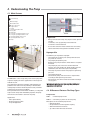
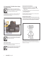
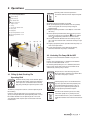
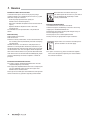
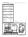
Betriebsanleitung • Operating Instructions
Rotary Vane Pump
DUO 5 M
PK 0197 BE/G (0603)
DUO 5 MC
INDEX
Page
1. Safety Precautions .................................. 3
1.1. For Your Orientation........................................................... 3
1.2. Pictogram Definitions........................................................ 3
2. Understanding The Pump........................ 4
2.1. Main Features..................................................................... 4
Proper Use.................................................................................... 4
Improper Use................................................................................ 4
2.2. Differences Between The Pump Types.......................... 4
3. Installation ............................................... 5
3.1. Preparations For Installation............................................ 5
3.2. Pump Set-Up And Location .............................................. 5
3.3. Connecting The Vacuum Side.......................................... 5
3.4. Connecting The Exhaust Side .......................................... 5
3.5. Connecting To The Mains Power Supply....................... 6
4. Operations ................................................ 7
4.1. Filling Up And Checking The Operating Fluid ................ 7
4.2. Switching The Pump ON And OFF................................... 7
4.3. Extracting Dry Gases And Vapours................................. 8
5. What To Do In Case Of
Breakdowns? .......................................... 9
6. Maintenance .......................................... 10
6.1. Replacing The Operating Fluid....................................... 10
6.2. Cleaning And Replacing The Silencer.......................... 11
6.3. Shutting Down For Longer Periods ............................... 11
7. Service .................................................... 12
8. Technical Data ....................................... 13
8.1. Dimensions........................................................................ 13
9. Accessories............................................ 14
10. Spare Parts ............................................. 15
10.1 Spare Parts Package....................................................... 15
10.2. Exploded view................................................................... 16
Declaration Of Contamination .................... 17
Conformity Declaration ................ (last page)
2
Please note:
Current operating instructions are also available via
www.pfeiffer-vacuum.net.
1. Safety Precautions
☞ Read and follow all the instructions in this manual.
☞ Inform yourself regarding:
– Hazards which can be caused by the pump;
– Hazards which can arise in your system;
– Hazards which can be caused by the medium being
pumped.
☞ Avoid exposing any part of your body to vacuum.
☞ Observe all safety and accident prevention regulations.
☞ Check regularly that all safety requirements are being
complied with.
☞ Do not use the pump for the purpose of generating
pressure.
☞ Do not carry out any unauthorised conversions or
modifications on the pump.
☞ When returning the pump to us please note the shipping
instructions in the section on service.
The following safety instructions are only relevant when
dismantling the drive system.
☞ When dismantling the drive system from the pump casing
the powerful magnetic field of the coupling system can
influence the function and operational safety of electrical
and electronic units.
BEWARE
1.2. Pictogram Definitions
BEWARE
WARNING
WARNING
CAUTION
Strong magnetic field!
Danger of personal injury.
Danger of personal injury.
Danger of burns from touching hot parts.
Danger of damage to the pump or system.
Persons who have a heart pacemaker must
stay outside the area of influence of magnetic
fields. There is a danger of life.
☞ Do not place the dismantled magnetic coupling in the vicinity of computers, data carriers and other electronic
components.
☞ On no account allow the two parts of the magnetic
coupling to come into contact. There is a danger of
crushing.
☞ Keep all magnetisable parts away from the magnetic
coupling. There is a danger of personal injury.
☞
PLEASE NOTE
Attention to particularly important information
on the product, handling the product, or to a
particular part of the documentation.
1.1. For Your Orientation
Instructions in the text
➡ Operating instruction: Here, you have to do something.
Symbols used
The following symbols are used throughout in the
illustrations:
Vacuum flange
Exhaust flange
Gas ballast valve
Power connection
Position numbers
Identical pump and accessory parts have the same position
numbers iin all illustrations.
Modifications reserved
3
2. Understanding The Pump
2.1. Main Features
New drive concept with integrated magnetic coupling
Rotary Vane Vacuum Pump DUO 5/DUO 5 C
Vacuum flange
Exhaust flange
Gas ballast valve
26
28
42
80
110
142
144
198
200
280
Power connection
Support stand
Casing
Housing gas ballast valve
Base plate
Sight glass
O-ring for operating fluid drain screw
O-ring for operating fluid filler screw
Operating medium drain screw
Operating fluid filler screw
Motor
Proper Use
28 200/144
110
42
– Rotary Vane Vacuum Pumps may only be used to generate
vacuum.
– Installation, start-up, operating and maintenance
instructions must be observed.
– Accessories other than those named in this manual may
not be used without the agreement of Pfeiffer Vacuum.
Improper Use
280
80
26
198/142
The DUO 5/5C is a dual stage rotary vane vacuum pump with
magnetic coupling for various applications in the rough and
medium vacuum.
The separation of the rotor and motor shaft eliminates the
problem of the radial shaft seal providing a hermeticalled
sealed pump. The wear-free drive prevents leaks, minimizes
maintenance and increases the MTTF.
During intentional and unintentional shutdowns, an integrated
high-vacuum safety valve immediately separates the pump
from the vacuum chambers and vents the pump.
Applications:
– Mass Spectrometry
– Backing pump for turbos
– Any Lab-Application
4
The following are regarded as improper:
– The pumping of corrosive gases (except with corrosive
gas processes version).
– The pumping of explosive gases.
– Operating the pump in locations where there is an explosion hazard.
– The pumping of gases which are contaminated with
particles, dust and condensate. Avoid condensation and
sublimation; take note to the vapour compatability.
– The Pump may not be used for the purpose of generating
pressure.
– The pumping of liquids.
– Connection to pumps and units which is not permitted
according to their operating instructions.
– Connection to units which contain touchable and voltage
carrying parts.
Improper use will cause any rights regarding liability and
guarantees to be forfeited.
2.2. Differences Between The Pump Types
Pump versions
DUO 5
= Standard pump version
DUO 5 C = Corrosive gas processes version pump
Divergences to the standard pump version:
– operating fluid F4
– encapsulated can of the magnetic coupling
– different material for the vanes
– gas vallast valve with hose connection
3. Installation
3.1. Preparations For Installation
3.3. Connecting The Vacuum Side
At pumps with three phase motors check the direction of
rotation before filling in the operating fluid. Pumps with single
phase motors are not concerned.
➡ Keep the connection between the vacuum chamber and
pump as short as possible.
➡ Remove all scaling and loose particles from welded lines
prior to assembly.
– To protect the pump, separators, filters and cooling traps
etc.(see Section 9. Accessories) can be fitted upstream of
the pump. However, the conductance values of the accessory causes a reduction in volume flow rate.
– For the intake lines, metal or PVC hoses with small flanges
are available.
CAUTION
Fill up with operating fluid before operating the
first time (included in a separate pack in the
delivery consignment).
When filled with operating fluid, do not tilt the
pump otherwise operating fluid could escape
via the vacuum and exhaust flanges.
3.4. Connecting The Exhaust Side
3.2. Pump Set-Up And Location
When transporting, use only the handle provided for the
purpose.
➡ Where stationary installation is involved, anchor the pump
on site.
➡ Sight glass 110 on the front side must be visible and the
gas ballast valve readily accessible.
➡ When installing the pump in a closed housing, ensure
there is sufficient air circulation.
Pressure can rise to dangerous levels in exhaust
lines. Therefore, exhaust lines, which should be
of minimum diameter DN 16, should not be fitted
with shut-off units. Lay lines from the pump
sloping downward so that no condensate can
flow back into the pump. Otherwise fit a separator.
If exhaust gases are extracted, the exhaust pressure must not
fall below 250 mbar .
Forces from the piping system may not be allowed to act on
rotary vane pumps which are anchored.
All piping to the pump must be suspended or supported.
CAUTION
Maximum angle of inclination to each side 10°
Maximum erection height 2000 m N.N
Maximum and minimum ambient temperature 40 °C
and 12 °C respectively
Maximum relative humidity 85%
max. 10°
5
3.5. Connecting To The Mains Power Supply
Single phase motor
CAUTION
Power connections must comply with local
regulations. Voltage and frequency information
given on the rating plate must correspond to the
mains voltage and frequency values.
The DUO 5/DUO 5 C is fitted with a single phase motor with
integrated thermal protection switch, power button and
connecting cable as standard.
DUO 5 with single phase motor
Checking The Direction Of Rotation
➡ Remove locking cap from the exhaust flange
.
➡ Switch on for a short time (2 ... 3 seconds)
Motor/motor fan must turn clockwise (see arrow on
support stand).
➡ If direction of rotation incorrect: Interchange two phases
on the connecting cable.
➡ Fill in operating fluid.
The motor protection switch has been set according to the
nominal voltage levels provided.
Three phase motors with PTC
The motors of these pumps are fitted with three PTCs which
are built into the stator windings. The connection of a tripping
unit and a contactor in the power supply line (according the
wiring diagram) will protect the pump against overloading.
Power part with motor to be protected
CAUTION
The transmission power of the pump’s magnetic
coupling is so great that there is no overload
protection for the motor.
Three phase motor
When switching on pumps with three phase motors for the
first time, check the direction of rotation:
WARNUNG
6
Always check the direction of rotation without
operating fluid filled in, otherwise operating
fluid could eject via the vacuum flange.
Use a tripping unit with error signal storage, e.g. a PTC
tripping unit with two switchover contacts at the output (see
Section 9. Accessories).
4. Operations
PLEASE NOTE
26
28
42
80
110
198
200
280
☞
Rotary Vane Pump DUO 5/DUO 5 C
Vacuum flange
Exhaust flange
Gas ballast valve
Power connection
Support stand
Casing
Housing gas ballast valve
Base plate
Sight glass
Operating fluid drain screw
Operating fluid filler screw
Motor
28
200 110
42
Operating fluid must be disposed of in
accordance with local waste disposal regulations.
➡ Remove operating fluid filler screw 200.
➡ Fill up with operating fluid included in the consignment;
refer to rating plate for correct quantity and typ of
operating fluid.
➡ Replace operating fluid filler screw 200; be careful with
the O-ring.
➡ Check operating fluid level only when the pump is warm
and running and vacuum connection
and gas ballast
valvel
and operating fluid filler screw are closed.
➡ The level should be between the two markings on sight
glass 110. The minimum level is the lower marking on sight
glass 110.
➡ Topping up operating fluid is possible when the pump is in
final vacuum operations.
➡ In non-stop operations check operating fluid daily,
otherwise whenever the pump is switched on.
4.2. Switching The Pump ON And OFF
280
80
26
198
The pump can be switched ON and OFF in any pressure
range.
Lowest start-up temperature, in compliance with German
Industrial Standard DIN 28 426: +12 °C.
On switching OFF (intake pressure < 750 mbar) the built-in
high vacuum safety valve to the vacuum chamber closes
automatically and the pump is vented.
WARNING
4.1. Filling Up And Checking The
Operating Fluid
Standard version pumps are tested with operating fluid P3. Guarantees relating to attainment
of final pressures and trouble free functioning
apply only providing this operating fluid is used.
The delivery consignment contains sufficient operating fluid
for one filling.
Pumps for special applications (e.g. for pumping corrosive
gases) can be operated with special operating fluids such as
F4 and other Pfeiffer Vacuum operating fluids. The use of
such operating fluids requires prior authorisation from the
manufacturer.
CAUTION
PLEASE NOTE
☞
CAUTION
Danger of burns when touching hot parts!
During operations temperatures of obove 70°C
can arise at the pump`s surface!
Protect pump by means of suitable measures
(e.g. dust separator) when the pumped gases
are contaminated with particles or dust. If
necessary check operating fluid regular or
change operating fluid more frequent.
To make shure that the high vacuum safety
valve works proper at any intake pressure,
there should be at least a pressure difference
of 250 mbar between the intake and the exhaust
side.
7
4.3. Extracting Dry Gases And Vapours
Gas ballast valve
No special measures are necessary providing the correct
pump version is being operated (selection of operating fluid,
materials etc.).
To avoid condensation in the pump, vapours
should only be pumped off when the pump is
warm and with gas ballast valve
open. Note
pump water vapour compatibility levels under
Section 8. Technical Data. When the process
has been completed, allow the pump to continue running for
about 30 minutes with open gas ballast valve for operating
fluid regeneration purposes.
CAUTION
Gas Ballast Valve (Standard Version)
Air is periodically fed into the working chamber at the
beginning of the compression phase via the gas ballast valve.
The gas ballast valve is shut when turning to the right to position 0 and open when turning to the left to position 1.
Intermediate settings are not possible.
Gas Ballast Valve (Corrosiv Gas Version)
If the pumping process requires the connection of flushing
gas, an elbow fitting can be provided for the gas ballast valve
in c version (please refer to Chapter 10. Spare Parts).
➡ Connect flushing gas at the gas ballast inlet 224.
➡ Adjust pressure of sealing gas.
➡ Open gas ballast valve.
☞
HINWEIS
Flushing gas pressure may not exceed 1.5 bar
(absolute). The type of flushing gas is
dependent on the medium being pumped. Our
specialists would be pleased to give advice
regarding the type and volume of flushing gas
required.
Gas ballast valve
224 Elbow fitting (c version)
224
8
closed
open
5. What To Do In The Case Of Breakdowns?
Problem
Pump doesn't attain final pressure
Unusual operating noises
Pump doesn't start
Possible Cause
• Pump dirty
• Operating fluid dirty
•
•
•
•
•
•
Leak in system
Silencer dirty
Pump stage damage
Ambient temperature <12 °C
Dirty pump stages
Damaged pump stages
Remedy
• Cleaning the pump
• Operate pump for a longer period with open gas
ballast valve or change operating fluid
• Repair leak
• Clean silencer or change as per section 6.2.
• Request repair by Pfeiffer Vacuum Service
• Warm up pump
• Request cleaning by Pfeiffer Vacuum Service
• Request repair by Pfeiffer Vacuum Service
Any other repairs may only be carried out by qualified personnel in conjunction with the service instructions.
9
6. Maintenance
When carrying out servicing work, take the following
precautions:
Always ensure the pump cannot be switched
WARNING
on when carrying out any work on the pump. If
necessary, remove the pump from the system to
carry out inspection work.
➡ Only dismantle the pump as far as is necessary in order to
repair defects.
➡ Dispose of used operating fluid in compliance with local
regulations.
➡ When working with synthetic operating media, toxic
substances and substances contaminated with corrosive
gases, the relevant instructions governing their use must
be observed.
➡ Only use benzine or similar agents for cleaning pump
parts. Do not use soluble cleaning agents.
WARNING
The operating fluid temperature can be as high
as 80 °C. During maintenance and repair work,
process related toxic gases and vapours can
escape from the operating fluid which may
become contaminated with harmful substances
(radioactive, chemical etc.).
Disposal of used operating fluid is subject to
the relevant regulations.
➡ Screw in operating fluid drain screw 198.
➡ Allow pump to run for about 10 seconds with open vacuum
flange.
➡ Drain off remaining operating fluid.
➡ In the case of serious contamination, the operating fluid
will have to be changed several times.
➡ Screw in operating fluid drain screw 198 with O-ring.
➡ Fill in fresh operating fluid and check level as per
section 4.1.
6.1. Changing The Operating Fluid
The rate of deterioration of the operating fluid depends on the
pump applications.
➡ The level of deterioration of organic operating fluids (for
example P3) can be read off from the colour scale in
accordance with DIN 51578 on the supplementary sheet
PK 800 219 BN/B, on request.
– The colour scale enables precise colour determination.
➡ Fill a specimen in a test tube or some similar vessel and
test by holding against the light.
➡ Where the discolouration is dark yellow to red brown
(equivalent to 4 ... 5 on the scale) change operating fluid.
CAUTION
Where organic operating fluids, for example P3,
are involved, the operating fluid should be
changed at least once a year!
Replacing The Operating Fluid
➡ Switch off the pump.
➡ Unscrew operating fluid drain screw 198 and drain operating fluid.
10
WARNING
Operating fluid can contain substances from
the medium pumped. Operating fluid must be
disposed of in accordance with the local
respective regulations.
Please request safety instruction data sheets for operating
fluids from Pfeiffer Vacuum.
6.2. Cleaning And Replacing The Silencer
6.3. Shutting Down For Longer Periods
The Silencer 44 is a nozzle inside the pump housing and
cannot be altered; when dirty it should either be cleaned or
replaced.
Should the pump have to be shut down for an longer period,
the complete pumping system must be adequately protected
against corrosion.
Dismantling
➡ Unscrew 2 cheesehead screws 182 from the casing.
➡ Remove the gas ballast valve housing 42 from the casing
28, taking care with o-ring 148.
➡ Unscrew silencer nozzle 44 and remove in vertical
direction; take care with o-ring 138.
➡ Clean silencer nozzle 44 and o-ring and replace if
necessary.
➡ Switch off pump.
➡ Unscrew operating fluid drain screw 198 and drain operating fluid as per Section 6.1.
➡ Screw in operating fluid drain screw 198; keep an eye on
the position of the O-ring.
➡ Allow pump to run for about 10 seconds with open vacuum
flange.
.
➡ Drain off remaining operating fluid.
➡ Fill up pump with fresh operating fluid: filling level - upper
end of sight glass 110.
If this amount of operating fluid is filled in, the level is
extremely high but this is necessary to protect all parts of the
pump against corrosion.
Dismantling silencer
28
42
44
51
138
141
148
182
211
224
Casing
Gas ballast valve housing
Silencer nozzle
Leaf spring
O-ring
O-ring
O-ring
Cheesehead screws
Washer
Elbow-fitting
CAUTION
182
42
Before operating, the operating fluid must be
reduced to its normal level.
28
141*
224*
211
44
138 51
148
* C version
11
7. Service
Before Returning:
➡ Dismantle all accessories.
➡ Drain lubricant.
➡ Attach a clearly visible notice: “Free of contamination” (to
the unit being returned, the delivery note and accompanying paperwork).
Harmful substances" are substances and preparations as
defined in current legislation. Pfeiffer Vacuum will carry out
the decontamination and invoice this work to you if you have
not attached this note. This also applies where the operator
does not have the facilities to carry out the decontamination
work. Units which are contaminated microbiologically, explosively or radioactively cannot be accepted as a matter of
principle.
Fill Out The Contamination Declaration
➡ In every case the "Contamination Declaration" must be
completed diligently and truthfully.
➡ A copy of the completed declaration must accompany the
unit; any additional copies must be sent to your local
Pfeiffer Vacuum Service Center.
Please get in touch with your local Pfeiffer Vacuum representatives if there are any questions regarding contamination.
12
WARNING
Decontaminate units before returning or
possible disposal. Do not return any units which
are microbiologically, explosively or radioactively contaminated.
Returning Contaminated Units
If contaminated units have to be returned for
maintenance/repair, the following instructions concerning
shipping must be followed without fail:
➡ Neutralise the pump by flushing with nitrogen or dry air.
➡ Seal all openings to the air.
➡ Seal pump or unit in suitable protective foil.
➡ Ship units only in appropriate transport containers.
PLEASE NOTE
☞
Do Make Use Of Our Service Facilities
In the event that repairs are necessary to your pump, a
number of options are available to you to ensure any system
down time is kept to a minimum:
– Have the pump repaired on the spot by our
Pfeiffer Vacuum Service Engineers;
– Return the individual components to the manufacturer for
repairs;
– Replace individual components with a new value
exchange units.
Local Pfeiffer Vacuum representatives can provide full
details.
Repair orders are carried out according to our
general conditions of sale and supply.
➡ If repairs are necessary, please send the unit together
with a short damage description to your nearest Pfeiffer
Vacuum Service Center.
8. Technical Data
Feature
Unit
DUO 5/DUO 5 C
Connection nominal diameter
Input
Output
DN 16 ISO-KF
DN 16 ISO-KF
Nominal pumping speed at
50 Hz
60 Hz
Pumping speed at
50 Hz
60 Hz
m3/h
m3/h
5.5
6.6
m3/h
m3/h
5
6
Final pressure
Total without gas ballast
Total with gas ballast
Exhaust pressure,, min.
Exhaust pressure, max.
mbar
mbar
mbar
mbar
< 5 • 10-3
< 2 • 10-2
> 250
< 1500
mbar
mbar
25
28
g/h
g/h
90
120
Water vapour compatibility
50 Hz
60 Hz
Water vapour capacity
50 Hz
60 Hz
Noise level without gas ballast
Alternating current version
dB(A)
Three phase current version
dB(A)
Operating fluid
l
Max. permissible operating temperature ÞC
(at 25 °C ambient temperature and
operating fluid P3, without gas ballast)
Rotation speed at
50 Hz
60 Hz
Rated power, motor
Alternating current version
Three phase current version
Weight, approx.
Alternating current version
Three phase current version
57
55
0.75
80
1/min
1/min
1415
1690
kW
kW
0.37
0.25
kg
kg
22
19
8.1. Dimensions
DUO 5/DUO 5 C
145
47
61
M
58
4,5
215
H
18
DN 16 ISO-KF
3
65
o7
79
107
216
100-114
o 7 variabel
135
248
L
L
H
M
Pump with three phase motor
433
204 (without motor protection switch)
223 (with motor protection switch)
215
Pump with alternating current motor
435 mm
221 mm
160
PK197_massb
217 mm
13
9. Accessories
Description
Size
Number
Dust Separator
STP 025
DN 25 ISO-KF
PK Z60 106
Oil Mist Filter
Oil Return Unit
Condensate Separator
Cooling Trap
Adsorption Filter
Adsorption Filter
ONF 16
ONFR
KAS 16
KLF 025
FAK 025
FBL 025
ZFO 0252)
DN 16 ISO-KF
PK Z40 003
PK 196 172 -T
PK Z10 003
PK Z80 006
PK Z30 006
PK Z30 106
Zeolite Trap
PTC Tripping Unit
Operating Fluid F4
Operating Fluid F4
Operating Fluid F4
DN 16 ISO-KF
DN 25 ISO-KF
DN 25 ISO-KF
DN 25 ISO-KF
DN 25 ISO-KF
1 litre
0,5 litre
0,25 litre
2) Filled with zeolite.
Please refer to the Pfeiffer Vacuum catalogue “Components
For Vacuum Technology” for further accessories, or on
request.
14
PK Z70 006
P 4768 051 FQ
PK 005 887 -T
PK 005 886 -T
PK 005 885 -T
Comments/
Operating Instructions
only with adapter
DN 25/16 (PK 800 120 BN)
PK 800 213 BN
PK 800 213 BN
PK 800 220 BN
PD 0015 BN
PD 0017 BN
PD 0017 BN
PD 0016 BN
Order Quantity
10. Spare Parts
Set of seals
The set of seals contains all seals including all o-rings of the
subassemblies.
Maintenance kit
The pack contains the o-rings of the operating fluid filler and
drain screw for changing the operating fluid. Also the o-ring
for the casing after cleaning the operating fluid sump is included.
Overhaul kit
The pack contains all wearing parts of the pump to replace
the following parts after dismantling the whole pump:
– Set of seals
– Wearing parts of the pumping system
– Wearing parts of the vacuum safety valve
– Wearing parts of the gas ballast valve
Set of vacuum safety valve
The pack contains the wearing parts of the vacuum safety
valve. Also the o-rings between valve housing and pumping
system and the o-ring of the casing are included.
Set of discharge valves
The pack contains the wearing parts of the discharge valves.
Also the wearing parts of the exhaust valve and the o-ring of
the casing are included.
Coupling kit
The pack contains the coupling halfs, can and the respective
o-ring.
10.1 Spare Parts Package
Pump type
Revision
index
DUO 5
DUO 5 C
up to “B”
wizhout
Set of seals
PK E30 005 -T
PK E30 005 -T
Maintenance kit
Overhaul kit
PK E31 004 -T
PK E31 004 -T
PK E32 008 -T
PK E32 006 -T
Vacuum safety valve
PK E34 004 -T
PK E34 004 -T
Discharge valves
PK E35 002 -T
PK E35 002 -T
Spare parts package No.
Parts according to the exploded view on the following pages
Set of seals
PK E30 005 -T
76, 112 138, 141, 142, 144, 147, 148, 149, 150, 152, 154, 156, 158, 160, 162, 254.
Maintenance kit
PK E31 004 -T
138, 144, 162.
Overhaul kit
PK E32 008 -T
PK E32 006 -T
PK E30 005 -T, 7, 8, 9, 10, 32, 44, 51, 100, 102, 106, 110, 114.
PK E30 005 -T, 7, 8, 9, 10, 32, 44, 51, 100, 102, 106, 110, 114.
Vacuum safety valve
PK E34 004 -T
30, 32, 34, 70, 100, 106, 108, 147, 152, 154, 160, 188, 204, 208, 220, 250.
Discharge valves
PK E35 002 -T
100, 102, 184, 204, 208.
Coupling kit
PK E36 005 -T
PK E36 006 -T
18, 20, 24, 184, 254.
18, 20, 24, 184, 254.
☞
PLEASE NOTE
The use of other spare parts than mentioned in
this instruction requires prior authorisation
from Pfeiffer Vacuum.
The spare parts packages listed above are only valid for the
pumps in standard versions. When ordering please be sure to
state the full information given on the rating plate.
Coupling kit
PK E36 005 -T
PK E36 006 -T
Only authorized, experienced and trained personnel are
permitted to make changes or perform maintenance or
repairs. Unapproved changes by the customer void all
warranty and liability claims against Pfeiffer Vacuum.
Please use our Service Training offers (information is also
available via www.pfeiffer-vacuum.net).
15
10.2.Exploded view
42
78/
138/
141/
148
76/
142
}
78
7
8
9
10
18
20
24
30
32
34
42
9
162
51
44
144
110/
112
188 30
84
142
7/
10
8/
10
34
204/
152
70/208/
100
32
147 250
188
106
154/
160
220 108
102
184
254
158 20
44
51
70
76
78
80
84
100
102
106
108
110
112
114
138
141
142
144
147
148
149
150
152
154
158
160
162
188
184
204
208
220
250
254
149
Vanes, rough stage
Vanes, medium stage
Hydraulic vanes
Compression spring
Central coupling, drive
Central coupling, pump
Can
Housing high vacuum safety valve
Valve plate
Valve cover for vacuum safety valve
Housing gas ballast valve (further
parts see Section 6.2.)
Silencer screw
Plate spring (gas ballast valve)
Valve trap
Rapid action coupling
Compression spring
Base plate
Oil nozzle
Valve buffer
Valve plate
Hydraulic piston
Compression spring, vacuum safety valve
Sight glass
Sight glass seal
Rubber foot
O-ring
O-ring
O-ring
O-ring
O-ring
O-ring
O-ring
O-ring
O-ring
O-ring
O-ring
O-ring
O-ring
Allan head screw
Allan head screw
Circlip
Compression spring for valve buffer
Screw
Compression spring for vacuum safety
valve
O-ring
150
PK200/1
24
16
184
80
18
114
Declaration of Contamination of Vacuum Equipment and Components
The repair and/or service of vacuum components will only be
carried out if a correctly completed declaration has been
submitted. Non-completion will result in delay.
The manufacturer could refuse to accept any equipment
without a declaration.
This declaration can only be completed and signed by authorised and qualified staff:
1. Description of component:
2. Reason for return:
- Equipment type/model: _________________________
_____________________________________________
- Code No.:
__________________________
_____________________________________________
- Serial No.:
__________________________
_____________________________________________
- Invoice No.:
__________________________
_____________________________________________
- Delivery Date:
__________________________
_____________________________________________
3. Equipment condition
4. Process related contamination
- Has the equipment been used?
yes ❐
no ❐
of equipment
- toxic
yes ❐ no ❐
- What type of pump oil was used?
___________________________________________
- corrosive
yes ❐ no ❐
- microbiological hazard*)
yes ❐ no ❐
- Is the equipment free from potentially harmful
substances?
yes ❐
(go to section 5)
no ❐
(go to section 4)
- explosive*)
yes ❐ no ❐
- radioactive*)
yes ❐ no ❐
- other harmful substances yes ❐ no ❐
*) We will not accept delivery of any equipment that has been radioactively or microbiologically contaminated without written
evidence of decontamination!
Please list all substances, gases and by-products which may have come into contact with the equipment:
Tradename
Product name
Manufacturer
Chemical name
(or Symbol)
Danger class
Precautions associated
with substance
Action if spillage or human
contact
1.
2.
3.
4.
5.
5. Legally Binding Declaration
I hereby declare that the information supplied on this form is complete and accurate. The despatch of equipment will be in
accordance with the appropriate regulations covering Packaging, Transportation and Labelling of Dangerous Substances.
Name of Organisation: _______________________________________________________________________________
Address:
_____________________________________
Post code: _____________________________________
Tel.:
______________________________________________________________________________________
Fax:
_____________________________________
Name:
______________________________________________________________________________________
Job title:
______________________________________________________________________________________
Date:
_____________________________________
Telex: ________________________________________
Company stamp: ________________________________
Legally binding signature: _____________________________________________________________________________
17
Konformitätserklärung
Declaration of Conformity
im Sinne folgender EU-Richtlinien:
pursuant to the following EU directives:
- Maschinen/Machinery 98/37/EG (Anhang/Annex IIA)
- Elektromagnetische Verträglichkeit/Electromagnetic Compatibility 89/336/EWG
- Niederspannung/Low Voltage 2006/95/EG
Hiermit erklären wir, daß das unten aufgeführte Produkt den Bestimmungen der EU-Maschinenrichtlinie 98/37/EG, der EU-Richtlinie über Elektromagnetische Verträglichkeit 89/336/EWG
und der EU-Niederspannungsrichtlinie 2006/95/EG entspricht.
We hereby certify, that the product specified below is in accordance with the provision of EU Machinery
Directive 98/37/EEC, EU Electromagentic Compatibility Directive 89/336/EEC and EU Low
Voltage Directive 2006/95/EC.
Produkt/Product:
DUO 5 M, DUO 5 MC
Angewendete Richtlinien, harmonisierte Normen und angewendete nationale Normen in Sprachen und
Spezifikationen:
Guidelines, harmonised standards, national standards in languages and specifications which have been
applied:
DIN EN ISO 12100-1, -2
EN 294
EN 50 081-1, -2
EN 61 010
EN 60335-1, -41
EN 60 204
EN 1012-2
Unterschriften/Signatures:
Pfeiffer Vacuum GmbH
Berliner Str. 43
35614 Asslar
Germany
Unterschriften:
(M. Bender)
Geschäftsführer
Managing Director
(Dr. M. Wiemer)
Geschäftsführer
Managing Director
Konf.I/2007
Vacuum is nothing, but everything to us!
Turbo Pumps
Rotary Vane Vacuum Pumps
Roots Pumps
Dry Vacuum Pumps
Leak Test Units
Valves
Flanges, Feedthroughs
Vacuum Measurement
Gas Analysis
System Technology
Service
Pfeiffer Vacuum Technology AG · Headquarters/Germany
Tel. +49-(0) 64 41-8 02-0 · Fax +49-(0) 64 41-8 02-2 02 · [email protected] · www.pfeiffer-vacuum.net