1
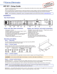
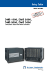
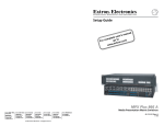
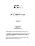
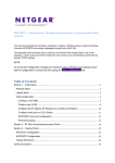
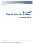
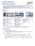
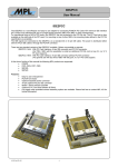
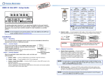
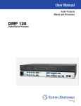
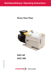
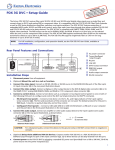
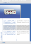
DVS 605 • Setup Guide
The Extron DVS 605 Digital Video Scalers are scaling products that allow most common signal formats to be processed, scaled, and
output in any desired format. This setup guide allows an experienced user to easily and quickly set up and configure a
DVS 605 using step by step instructions. It covers how to perform basic operations using the front panel controls and selected
Simple Instruction Set (SIS™) commands.
NOTE: For full installation, configuration, menus, connector wiring, and operation details, see the DVS 605 User Guide, available at
www.extron.com
Installation
Rear Panel Features
The DVS 605 AD is shown here. All other DVS 605 models have some but not all of the features shown below.
2
DVS 605 AD
6
INPUT
14
7
OUTPUTS
REMOTE
1
5
3
AUX
UNIVERSAL
2
4
1
GENLOCK
AUDIO INPUTS
CONTACT
1
HDMI
100-240 VAC ~ .7A MAX
50/60Hz
15
3G/HD - SDI
1 2 3 4 5
RS-232
RESET
HDMI
RGB/R-Y, Y, B-Y
4
5
LAN
11
12
L
IR
Tx Rx G G
2
R
L
AUDIO OUTPUTS
3
R
L
4
R
L
5
R
L
R
L
FIXED
FIXED
VARIABLE
L
R
S/PDIF
S
13
R
3
8
9
10
Mounting and Cabling
Step 1 — Mounting
Turn off or disconnect all equipment power sources and rack mount the
DVS 605 unit using the pre-installed brackets (see figure 1 at right).
Optional furniture mounting brackets (MBU 149) can be used to mount
the unit under a table or desk top (see figure 2 at right).
Step 2 — Connect inputs
Connect inputs from video sources to the applicable connectors
marked “Inputs”. See a and b for video connectors and c for audio connectivity.
Step 3 — Connect outputs
Rack Mount
Bracket
Connect video and audio output devices to the applicable connectors marked
“Outputs” (see d through j above).
Step 4 — Connect control devices
Figure 1. Rack Mount
LAN port l — Connect a LAN or WAN via this RJ-45 connector
for remote control of the DVS 605 using an Internet browser via
a connected PC.
NOTES:
• Default IP address is 192.168.254.254
• DHCP is disabled.
Mounting Screws
(2) Places
Each Side
One connection LED lights green when connected to the LAN and one flickers
amber as the devices communicate.
NOTE: Do not use standard telephone cables for LAN connection, as they do
not support Ethernet or Fast Ethernet.
Do not stretch or bend cables as transmission errors could occur.
RS-232/IR port — For serial RS-232 control, connect a host computer or
control system to the 5-pole captive screw connector m.
RS-232 protocol (default values):
9600 baud, 1 stop bit, no parity, 8 data bits, no flow control.
By default the IR port is disabled.
#8 Screw
(4) Places
Each Side
MBU 149
Mounting Bracket
Figure 2. Furniture Mount
Contact closure port — For remote input selection of any of the five inputs, connect a suitable contact closure control device to the
5-pole captive screw connector n. The contact closure port and the RS-232 port share a common ground.
Step 5 — Connect power
AC power connector — Plug in a standard IEC power cord from a 100 - 240 VAC, 50 - 60 Hz power source into this receptacle o.
1
DVS 605 • Setup Guide (Continued)
Powering Up
When the DVS 605 powers up, it performs a self testing sequence (see image below). The LCD displays the default display cycle,
with the signal type, resolution, and refresh rate for the currently selected input and the output resolution and refresh rate.
NOTE: When powered and not in any menu, the LCD screen defaults to cycling through the current input/output status. The displayed content
may vary depending on the input video signal type (see typical default display below).
Apply
Power
13 sec.
Display screen
starts blank.
EXTRON
ELECTRONICS
All input LEDs flash
(red then green).
1
2
3
4
5
PIP
Note: Times shown are approximate.
16 sec.
EXTRON
DVS 605 XX
11 sec.
Default Display Cycle
60-1059-xx
FW v1.xx
2
sec.
IN RGBHV
#1 640x480
2 sec.
IN 31.47 kHz
#1 59.94 Hz
OUTPUT
720p@60
2 sec.
Last active input
button(s) remains lit.
2 sec.
1
Front Panel Overview
The DVS 605 is shown here. All other models have the same features shown below.
3
DVS 605
1
2
4
5
3
PIP
SWAP
CONFIG
1
2
4
DIGITAL VIDEO SCALER
MENU
AUTO
EXTRON
DVS 605
5
ADJUST
NEXT
6
7
a Front panel mini USB configuration port — Connect a control system or computer to this mini USB port (cable not supplied), for
device configuration, control, and upgrading the firmware.
b Input selection buttons and LEDs (1-5) — Selects and switches inputs; adjacent LEDs indicate which input is active (current
input lights green, PIP (Picture-In-Picture) input lights red).
c Auto-Image™ (Auto) button — When pressed, this initiates automatic image size and centering adjustments on the selected input.
d PIP and Swap Image buttons — These two buttons are:
• PIP — Opens or closes the PIP window
• Swap — Swaps the main displayed image and the current PIP input with each other, or when not in PIP mode, it switches
between current and previous input.
e LCD display — This 12x2 screen displays device settings and menu configuration information.
f Menu navigation buttons (Menu, Next) — These buttons allow navigation through the menu system of the DVS 605.
g Adjust knobs — These are used with the menu navigation buttons to adjust the device settings and picture control.
Setting the Front Panel Locks (Executive Modes)
The DVS 605 has three modes of front panel security lock that limit the operation of the unit from the front panel.
Executive mode 0 (disabled) — The front panel is fully unlocked. This is the default setting.
Executive mode 1 (enabled) — The front panel is completely locked. Can only be enabled and disabled using SIS commands, or
through the embedded web pages. See the online DVS 605 User Guide or rear page of this guide for SIS commands.
Executive mode 2 (enabled) — The front panel is locked except for input switching, PIP, swap, and Auto-Image.
Enabling or disabling Executive mode 2 from the front panel
If the DVS 605 unit is in Executive mode 0 (unlocked), the procedure shown at right selects
mode 2 (locked). If it is in Executive mode 2, this procedure selects mode 0 (unlocked).
When Executive mode 2 is enabled and a front panel action is attempted (other than input
switching, PIP enable or disable, swap, and Auto-Image), the LCD displays the lock status
for 2 seconds.
2
LCD screen displays
either
MENU
Press and
hold for about
2 seconds.
NEXT
EXEC. MODE 2
ENABLED
or
EXEC. MODE
DISABLED
Configuring the DVS 605
DVS 605 devices can be configured by any of the following: via the front panel, via the internal web pages, or via RS-232/Ethernet
or USB connection, using the SIS commands (see the rear page).
Front Panel Menu System
The scaler has seven front panel configuration menus: • User Presets • Picture Control • Input Configuration • Output Configuration
• Audio Configuration • Advanced Configuration • View Comm Settings • Exit Menu. A hidden menu (Edit Comm Settings) is also
accessible (see note after the following figure).
Default Display Cycle
IN RGBHV
#1 640x480
2 sec.
2
sec.
OUTPUT
720p@60
Menu
USER
PRESETS
IN 31.47 kHz
#1 59.94 Hz
Menu
PICTURE
CONTROL
Menu
INPUT
CONFIG
OUTPUT
CONFIG
Menu
Menu
2 sec.
AUDIO
CONFIG
Next
Menu
ADVANCED
CONFIG
Menu
VIEW COMM
SETTINGS
Menu
Menu
EXIT MENU?
PRESS NEXT
Menu
Next
NOTE: To access the hidden Edit Comm Settings menu, press and hold the Input 5 and the Next button simultaneously. Release buttons when
the menu appears. Edit the setting as needed, then press Menu to exit and save the settings.
To use any menu, press the Menu button to access the main menu, then repeatedly press the Menu button to cycle through to the
desired menu. Press the Next button to enter and cycle through the desired submenu.
NOTE: Press Menu at any time to exit a submenu and return to the main menu.
For detailed information on the menus, see the DVS 605 User Guide, available online at www.extron.com.
To configure the DVS 605 using the front panel, follow the steps below:
1.
Within the Output Configuration menu, use the Adjust knobs to select the output resolution and refresh rate, the output signal
type, and the sync polarity to match the requirements of the analog display device. The HDMI format can be set to match the
connected HDMI display.
2.
From the Advanced Configuration menu, Test Pattern submenu, select the Alternating Pixels (Alt. Pixels) test pattern. Adjust the
connected analog display active pixels (size), total pixels (clocking), and pixel phase (fine sync) settings for optimal picture quality.
3.
From the Advanced Configuration menu, change the test pattern to Crop, and adjust the image position settings until all four sides
of the crop pattern are visible. Disable the test pattern. No further adjustments or Auto-Image functions should be performed on the
display device itself.
4.
Use the Advanced Configuration menu to set the Aspect Ratio (Fill or Follow) for each input. Rotate either Adjust knob to the desired
setting.
5.
Perform an Auto-Image on each DVS 605 input. Auto-Image is a quick way to size an input to fit the current window size.
To perform Auto-Image on the current input, press the Auto-Image button, then press it again to confirm.
NOTE: Alternatively using the Input Configuration menu, make any desired advanced adjustments, including turning on or off Film detection,
Horizontal and Vertical Start, Active Lines, Pixel Phase, and EDID setting selection.
6.
Adjust the Overscan mode under the Advanced Configuration menu as required. Overscan masks Closed Caption and ancillary data
common on broadcast signals. (Applies to SMPTE input resolutions only.)
7.
Use the Picture Control buttons to adjust the Horizontal and Vertical Position and Size, Brightness and Contrast, Color and Tint, and
Detail settings if needed.
8.
Use the User Presets menu to save the adjustments to each input for manual recall later.
Internal Web pages
The DVS 605 can be configured, controlled, and operated through the Ethernet port when connected to a LAN or WAN, using a web
browser such as Microsoft® Internet Explorer®. The browser displays the factory-installed web pages, which provide a means of
viewing and operating the device. Access the HTML pages by entering the IP address of the unit in the browser Address field.
NOTE: If the system administrator has not changed it, the factory default IP address is 192.168.254.254. DHCP is disabled. If the unit is
password-protected, enter the administrator or user password in the Password field.
A user name entry is required. Enter admin for administrator level or user for user level (all lower case letters).
3
DVS 605 • Setup Guide (Continued)
Upgrading the Firmware Using the Web Pages
The onboard firmware version of the DVS 605 unit can be upgraded via the factory-installed web pages when connected via the
Ethernet port to a LAN or WAN, using a web browser such as Microsoft Internet Explorer.
Firmware upgrade files (with an EFF or ESS extension) for the DVS 605 unit are available at www.extron.com. At the website, browse
to the file location and download the latest firmware version to a PC connected to the DVS 605.
Access the DVS 605 internal web pages by entering the IP address of the unit in the browser Address field.
When the web pages open do the following:
1.
Click the Hardware button above the global navigation bar.
2.
Click the Firmware Loader icon on the global navigation bar. The Firmware Loader screen opens.
3.
Click Browse. The Choose File to Upload dialog box opens.
4.
Browse to and select the downloaded firmware file to upload to the device. Valid firmware files have an EFF or ESS extension.
5.
Click Open. This closes the dialog box and returns you to the Firmware Loader screen.
6.
Click Upload. Uploading progress is displayed and will indicate when completed.
7.
When the upload is complete the unit reboots. Any IP connections to the unit need to be re-established.
Basic SIS Commands Table
The DVS 605 can be configured with specific SIS commands via an RS-232, USB, or LAN connection. This table lists a selection of
the commands. For a full list of SIS commands and variables see the DVS 605 User Guide, online at www.extron.com.
Command
ASCII command
(host to scaler)
(scaler to host)
Select video and audio input
X!!
InX!•All]
Selects video and audio from input X!.
Select video input
X!&
InX!•RGB]
Selects video only from input X!.
Select audio input
X!$
InX!•Aud]
Selects audio only from input X!.
Execute Auto-Image
0*A
Img0]
Executes Auto-Image for current input.
Mute video to black
1B
2B
Vmt1]
Vmt2]
Mutes video and display a black screen.
Mute video and output sync
Unmute video
0B
Vmt0]
Unmutes video.
PIP on
EX!PIP}
PipX!]
Turns on PIP and displays input X!.
PIP off
E0PIP}
Pip00]
Turns off PIP.
Swap
%
Tke]
Recall PIP preset (without input)
3*X2@ .
3RprX2@]
Swaps inputs between main and PIP windows, or current and
previous input when not in PIP mode.
Recalls PIP preset X2@ without input.
Recall PIP preset (with input)
4*X2@ .
4RprX2@]
Recalls PIP preset X2@ with input.
Save PIP preset
4*X2@ ,
4SprX2@]
Saves PIP preset X2@.
Enable Executive mode 1
1X
2X
0X
X
Exe1]
Exe2]
Exe0]
0] (or 1])
Locks out entire front panel.
Enable mode 2
Disable Executive mode
View front panel lock status
Response
Additional description
Mutes video and sync output.
Allows limited front panel adjustments only.
Allows all front panel adjustments and selections.
Shows executive mode status.
(or 2])
NOTE: Changes made to all Ethernet settings do not take effect until the reboot networking command (2BOOT) is issued.
Set DHCP to Off or On
View DHCP status
Set IP address
View IP address
Reboot network
NOTE:
EX1&DH}
EDH}
EX1(CI}
ECI}
E2BOOT}
IdhX1&]
X1&]
Sets DHCP mode (default setting is 0 = off).
IpiX1(]
X1(]
Sets IP address to X1( (default IP is 192.168.254.254)
Boot2]
Restarts network after IP address or DHCP changes.
Shows DHCP setting.
Shows current IP address X1(.
X! = Input number (1 – 5) X1& = DHCP mode: 0 = Off (default), 1 = On X1( = IP address, such as 192.168.254.254 (default)
X2@ = PIP presets (1-16)
Extron Headquarters
+1.800.633.9876 (Inside USA/Canada Only)
Extron Asia
+65.6383.4400
Extron China
+86.21.3760.1568
Extron Korea
+82.2.3444.1571
Extron Europe
+31.33.453.4040
Extron Japan
+81.3.3511.7655
Extron Middle East
+971.4.2991800
Extron India
+91.80.3055.3777
© 2013 Extron Electronics — All rights reserved. All trademarks mentioned are the property of their respective owners.
4
www.extron.com
68-2110-50
Rev.C
06 13