1
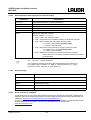
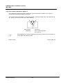
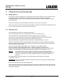
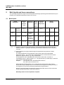
Operating instructions
LAUDA Water Circulation coolers
WK 500, WK 502, WK 1200 (W),WK 1400 (W),
WK 2200 (W), WK 2400 (W),WK 3200 (W),
WK 4600 (W), WK 7000 (W), WK 10000 (W),
WKL 230, WKL 600, WKL 603,
WKL 700, WKL 703, WKL 900, WKL 903
WKL 1200 (W), WKL 2200 (W), WKL3200 (W)
WKL 4600 (W), WKL 7000 (W), WKL 10000 (W)
from serie A10
01/02
YAWE0019
LAUDA DR. R. WOBSER
GMBH & CO.KG
P.O.Box 1251
D-97912 Lauda-Königshofen
Phone.: (+49) (0)9343/ 503-0
Fax: (+49) (0)9343/ 503-222
e-mail info @ lauda.de
Internet http://www.lauda.de
LAUDA water Circulation coolers
WK, WKL
1
BRIEF OPERATING INSTRUCTIONS ................................................................................. 4
2
TECHNICAL DATA............................................................................................................... 5
3
BASIC CONSTRUCTION AND TECHNICAL DESCRIPTION............................................ 13
3.1 Standard version .......................................................................................................................................... 13
3.2 Options .......................................................................................................................................................... 17
3.2.1 Enlarged temperature range to –25°C, Option 2...................................................................................... 17
3.2.2 High-power pump, Option 3 ..................................................................................................................... 17
3.2.3 Serial digital Interface RS 232, RS 485, Option 4 .................................................................................... 17
3.2.3.1
Configuration................................................................................................................................... 17
3.2.3.2
RS 232 interface ............................................................................................................................. 19
3.2.3.3
RS 485 Interface............................................................................................................................. 21
3.2.3.4
Write commands (setpoint transfer to the thermostat)................................................................... 22
3.2.3.5
Read commands (data requested from the thermostat)................................................................. 23
3.2.3.6
Error messages .............................................................................................................................. 23
3.2.3.7
Driver software for LABVIEW ........................................................................................................ 23
®
3.2.4 Flow control instrument, Option 5............................................................................................................. 24
4
SAFETY DEVICES AND WARNING NOTES ..................................................................... 25
4.1 Safety devices ............................................................................................................................................... 25
4.2 Warning notes............................................................................................................................................... 25
5
BATH LIQUIDS AND HOSE CONNECTIONS.................................................................... 26
5.1 Bath liquids ................................................................................................................................................... 26
5.2 Hose connections (by the metre) ................................................................................................................ 27
6
UNPACKING, ASSEMBLY AND SETTING UP.................................................................. 28
7
FILLING AND CONNECTION OF EXTERNAL CONSUMING DEVICES........................... 29
8
STARTING UP .................................................................................................................... 30
9
MAINTENANCE .................................................................................................................. 32
9.1 Maintenance of the refrigeration unit ......................................................................................................... 32
9.2 Trouble-shooting and safety notes............................................................................................................. 32
9.3 Repair and disposal instruction .................................................................................................................. 33
9.4 Cleaning......................................................................................................................................................... 33
9.5 Spares ordering ............................................................................................................................................ 33
YAWE0019/05.06.02
- 3-
LAUDA water circulation coolers
WK, WKL
1
Brief operating instructions
Even if you find these brief instructions initially sufficient please read the subsequent sections, especially
Section 4: "Safety devices and warning notes".
Check the Water circulation cooler and accessories during unpacking for any transport damage and if
necessary inform the carrier.
Assemble the unit according to Section 6 and add extra items as appropriate.
When setting up the unit there must be a spacing of at least 0,5 m between the grills and any object
which could interfere with ventilation.
With the pump connections open fill the bath up to the top mark on the level indication: in the case of
WK 230 up to about 20 mm below the bath cover plate. Check that the drain valve on the back wall is
closed.
Connection of the hoses to the pump connections:
Connect the connecting hose to the external device. Protect the tubes with hose clips against slipping
off.
Use only tubes suitable for the liquid used and for the maximum operating pressure!
Check the supply voltage against the details on the label. Insert the mains plug.
Test the sense of rotation of the three-phase alternating current connection at WKL 7000 (W) and
WKL 10000 (W).
Check that the tube connections have been made according to Item 1.5 and that the unit has been filled
according to Item 1.4! Switch on the mains switch (I). The temperature indicator on the control panel
shows the current bath temperature.
Display and modification of the set point: Press key
press again
for a short time ➾ the set point is indicated (
Set the temperature with the keys
Memorizing is done by pressing the key
The indication
for approx. 2 s ➾
or
is displayed. Then
flashes).
.
(approx. 2 s) or automatically after 10 s.
shows if the compressor is running, i.e. if the unit is being cooled down or not.
The pressure gauge shows the pump pressure at the outflow connection (outlet) of the unit. The
pressure can be adjusted with the bypass valve at the back of the unit (see 8.4). Not on WKL 230, WK
500, WK 502, WKL 600, WKL 603, WKL 700 und WKL 703, WLK 900, WKL 903!
YAWE0019/05.06.02
- 4-
LAUDA water Circulation coolers
WK, WKL
2
Technical Data
Type
WK 500
Working temperature range
[ °C ]
Condenser cooling
Ambient temperature range
[ °C ]
WK 502
WK 1200
0...40
0...40
0...40
0...40
0...40
0...40
air
air
water
air
water
5...40
5...40
5...40
5...40
5...40
5...40
PTC
green 7-Segment-LED-display
[ °C ]
Setpoint adjustment
Temperature accuracy
WK 1400 W
air
Temperature (outflow), sensor
Indication
Resolution/accuracy:
WK 1200 W WK 1400
[ ±°C ]
0.1 / ±0.3*)
0.1 / ±0.3*)
0.1 / ±0.3*)
0.1 / ±0.3*)
0.1 / ±0.3*)
0.1 / ±0.3*)
Digital
Digital
Digital
Digital
Digital
Digital
0.5*)
0.5*)
0.5*)
0.5*)
0.5*)
0.5*)
Control
Compr. On-Off, with stop interval monitoring
Eff. cooling capacity
20°C [ kW ]
0.5
0.6
1.2
1.5
1.4
1.7
(with Ethanol at ambient
10°C
0.3
0.5
0.9
1.1
1.1
1.3
5°C
0.18
0.4
0.6
0.8
0.8
1.0
0°C
0.05
0.3
0.28
0.32
0.5
0.7
temperature 20°C)
Safety devices
Pressure switch, Winding temperature control
Level indication, adjustable alarm contact (/max. 30V, 2A)
Pump output max.
30
33
40
40
30
30
Discharge pressure max.
[ bar ]
1
2,2
3,2
3,2
1
1
Pump connections
(for tubing)
[ i.d. ]
M 16x1
10 (½“)
M 16x1
10 (½“)
G ¾“
15 (¾“)
G ¾“
15 (¾“)
G ¾“
15 (¾“)
G ¾“
15 (¾“)
Supply pressure/ Indication/ Range
Adjustment
[ bar ]
Filling capacity max.
Overall dimensions (B x T x H)
[l]
[ mm ]
Weight
[ kg ]
Protection to DIN 40050
analogue / 0...6
adjustable bypass for pressure limitation
12
350x480x
595
12
350x480x
715
23
450x550x
790
23
450x550x
790
23
450x550x
790
23
450x550x
790
46
50
75
75
69
69
IP 32
IP 32
IP 32
IP 32
IP 32
IP 32
Mains connection
[ V;Hz ]
230; 50
230; 50
230; 50
230; 50
230; 50
230; 50
Power consumption
[ kW ]
0.47
0.9
1.2
1.2
1.0
1.0
Class according to
EMC-standards 61326-1 *)
(Notice only valid for EUcountries)
B
Ref-No.:
230V; 50Hz
230V; 60Hz
Options:
Pump 5,5 bar; 40 L/min
50Hz
Pump 5,5 bar; 40 L/min
60Hz
Serial Interface
RS 232/485 galv. sep.
Flow control instrument
Protection class 1 according to DIN VDE 0106
Units conform to EU Guideline 89/336/EWG (EMC) and 73/23/EWG (low
voltage) and carry the CE mark (230V;50Hz)
B
B*
B*
B*
B*
LWG 132
LWG 232
LWG 140
-----
LWG 133
LWG 233
LWG 137
LWG 237
LWG 134
LWG 234
LWG 138
LWG 238
3
3
4
--------LWZ 033
--------LWZ 033
LWZ 031-1
LWZ 031-2
LWZ 033
LWZ 031-1
LWZ 031-2
LWZ 033
--------LWZ 033
--------LWZ 033
5
LWZ 034
LWZ 034
LWZ 035
LWZ 035
LWZ 035
LWZ 035
*) see 4.2
We reserve the right to make technical alterations!
YAWE0019/05.06.02
- 5-
LAUDA water circulation coolers
WK, WKL
Type
WK 2200
Working temperature range
[ °C ]
Condenser cooling
Ambient temperature range
[ °C ]
WK 2200 W WK 2400
WK 3200 W
0...40
0...40
0...40
0...40
0...40
0...40
air
water
air
water
air
water
5...40
5...40
5...40
5...40
5...40
5...40
Temperature (outflow), sensor
Indication
Resolution/accuracy
WK 2400 W WK 3200
PTC
green 7-segment-LED-display
[ °C ]
0.1 / ±0.3*)
0.1 / ±0.3*)
0.1 / ±0.3*)
0.1 / ±0.3*)
0.1 / ±0.3*)
0.1 / ±0.3*)
Digital
Digital
Digital
Digital
Digital
Digital
[ ±°C ]
1*)
1*)
1*)
1*)
1*)
1*)
[ kW ]
2.2
2.6
2.4
2.8
3.5
4.0
(with Ethanol at ambient 10°C
1.6
1.9
1.8
2.1
3.0
3.5
temperature 20°C)
5°C
1.2
1.5
1.4
1.7
2.3
2.6
0°C
0.8
1.0
1.0
1.2
1.2
1.5
Setpoint selection
Temperature accuracy
Control
Eff. cooling capacity
Compr. On-Off, with stop interval monitoring
20°C
Safety devices
Pressure switch, Winding temperature control
Level indication, adjustable alarm contact (max. 30 V, 2A)
Pump output max.
40
40
30
30
40
40
Discharge pressure max.
[ bar ]
3.2
3.2
1
1
3.2
3.2
Pump connections
(for tubing)
[ i.d. ]
G ¾“
15 (¾“)
G ¾“
15 (¾“)
G ¾“
15 (¾“)
G ¾“
15 (¾“)
G ¾“
15 (¾“)
G ¾“
15 (¾“)
Supply pressure/ Indication/ Range
Adjustment
[ bar ]
Filling capacity max.
Overall dimensions (B x T x H)
[l]
[ mm ]
Weight
analogue / 0...6
adjustable bypass for pressure limitation
23
450x550x
790
23
450x550x
790
23
450x550x
790
23
450x550x
790
45
550x650x
970
45
550x650x
970
[ kg ]
87
87
81
81
120
120
Protection to DIN 40050
Mains connection
[ V;Hz ]
IP 32
230; 50
IP 32
230; 50
IP 32
230; 50
IP 32
230; 50
IP 32
230/400;
3/N/PE 50
IP 32
230/400;
3/N/PE 50
Power consumption
[ kW ]
1.6
1.6
1.4
1.4
2.0
2.0
Protection class 1 according to DIN VDE 0106.
Units conform to EU Guideline 89/336/EWG (EMC) and 73/23/EWG (low-voltage) and carry the
CE mark (230 V; 50 Hz or 230/400 V; 3/N/PE 50 Hz)
B*
B*
B*
B*
A
A
Class according to
EMC-standards 61326-1 *)
(Notice only valid for EUcountries)
Ref.-No.
230V; 50Hz
230V; 60Hz
230V; 3/PE 60Hz
230/400V; 3/N/PE 50Hz
Options:
Pump 5,5 bar; 40 L/min
50Hz
Pump 5,5 bar; 40 L/min
60Hz
Serial Interface
RS 232/485 galv. sep.
Flow control instrument
LWG 134
LWG 234
---------
LWG 163
-------------
LWG 138
LWG 238
---------
LWG 164
-------------
--------LWG 135
LWG 235
--------LWG 136
LWG 236
3
3
4
LWZ 031-1
LWZ 031-2
LWZ 033
LWZ 031-1
LWZ 031-2
LWZ 033
--------LWZ 033
--------LWZ 033
LWZ 032-1
LWZ 032-2
LWZ 033
LWZ 032-1
LWZ 032-2
LWZ 033
5
LWZ 035
LWZ 035
LWZ 035
LWZ 035
LWZ 035
LWZ 035
*) see 4.2
We reserve the right to make technical alterations!
YAWE0019/05.06.02
- 6-
LAUDA water circulation coolers
WK, WKL
Typ
WK 4600
Working temperature range
[ °C ]
Condenser cooling
Ambient temperature range
[ °C ]
WK 4600 W WK 7000
0...40
0...40
0...40
0...40
0...40
0...40
water
air
water
air
water
5...40
5...40
5...40
5...40
5...40
5...40
[ °C ]
[ ±°C ]
0.1 / ±0.3*)
0.1 / ±0.3*)
0.1 / ±0.3*)
0.1 / ±0.3*)
0.1 / ±0.3*)
0.1 / ±0.3*)
Digital
Digital
Digital
Digital
Digital
Digital
0.5*)
0.5*)
0.5*)
0.5*)
0.5*)
0.5*)
Control
Eff. cooling capacity
WK 10000 W
PTC
green 7-segment-LED-display
Setpoint selection
Temperature accuracy
WK 10000
air
Temperature (outflow), Sensor
Indication
Resolution/accuracy
WK 7000 W
push-pull control with solenoid valves
20°C
[ kW ]
(with Ethanol at ambient 10°C
temperature 20°C)
4.6
5.3
7.0
8.5
10.0
13
3.4
4.0
6.0
7.0
9.0
11
5.5
6.3
8.2
5°C
2.3
2.6
0°C
1.2
1.5
40
40
Safety devices
Pump output max.
Discharge pressure max.
Pump connections
(for tubing)
5.0
5.5
7.3
Pressure switch, Winding temperature control
Level indication, adjustable alarm contact (max. 30 V, 2A)
40
40
9.9
8.7
40
40
[ bar ]
3.2
3.2
3.2
3.2
3.2
3.2
[ l.W. ]
G ¾“
15 (¾“)
G ¾“
15 (¾“)
G ¾“
15 (¾“)
G ¾“
15 (¾“)
G ¾“
15 (¾“)
G ¾“
15 (¾“)
Supply pressure/ Indication/ Range
Adjustment
[ bar ]
Filling capacity max.
Overall dimensions (B x T x H)
[l]
[ mm ]
45
550x650x
970
45
550x650x
970
45
850x670x
970
45
850x670x
970
45
1050x770x
1120
45
850x670x
970
Weight
[ kg ]
123
128
172
177
233
240
IP 32
Protection to DIN 40050
Mains connection
Power consumption
IP 32
IP 32
IP 32
IP 32
IP 32
[ V;Hz ] 230/400;
3/N/PE 50
230/400;
3/N/PE 50
230/400;
3/N/PE 50
230/400;
3/N/PE 50
230/400;
3/N/PE 50
230/400;
3/N/PE 50
[ kW ]
2.5
5.0
4.7
6.5
6.0
2.5
Protection class 1 according to DIN VDE 0106.
Units conform to EU Guideline 89/336/EWG (EMC) and 73/23/EWG (low-voltage) and carry the
CE mark (230 V; 50 Hz or 230/400 V; 3/N/PE 50 Hz)
A
A
A
A
A
A
Class according to
EMC-standards 61326-1 *)
(Notice only valid for EUcountries)
Ref.-No.
230V; 3/PE 60Hz
230/400V; 3/N/PE 50Hz
440/480V; 3/PE 60Hz
Options:
Pump 5,5 bar; 40 L/min 50Hz
Pump 5,5 bar; 40 L/min 60Hz
Serial interface
RS 232/485 galv. sep.
Flow control instrument
Analogue / 0...6
adjustable bypass for pressure limitation
LWG 136
LWG 236
-----
----LWG 258
-----
----LWG 245
LWG 645
----LWG 247
LWG 647
----LWG 249
LWG 649
----LWG 251
LWG 651
3
3
4
LWZ 032-1
LWZ 032-2
LWZ 033
LWZ 032-1
LWZ 032-2
LWZ 033
LWZ 032-1
LWZ 032-2
LWZ 033
LWZ 032-1
LWZ 032-2
LWZ 033
LWZ 032-1
LWZ 032-2
LWZ 033
LWZ 032-1
LWZ 032-2
LWZ 033
5
LWZ 035
LWZ 035
LWZ 035
LWZ 035
LWZ 035
LWZ 035
*) see 4.2
We reserve the right to make technical alterations!
YAWE0019/05.06.02
- 7-
LAUDA water circulation coolers
WK, WKL
Type
Working temperature range
[ °C ]
Condenser cooling
Ambient temperature range
[ °C ]
WKL 230
WKL 600
WKL 603
WKL 700
WKL 703
WKL 900
WKL 903
-10...40
-25...40
-20...40
-9,9...40
-5...40
-20...40
-15...40
air
air
air
air
air
air
air
5...35
5...40
5...40
5...40
5...40
5...40
5...40
Temperature (outflow), Sensor
Indication/ accuracy
Resolution > -10/ < -10
PTC
green 7-Segment-LED-Display / 0,5*)
[ °C ]
Setpoint selection
Temperature accuracy
[ ±°C ]
0.1/ 1
0.1/ 1
0.1/ 1
0.1/ 1
0.1/ 1
0.1/ 1
0.1/ 1
Digital
Digital
Digital
Digital
Digital
Digital
Digital
0.5*)
1*)
1*)
1*)
1*)
1*)
1*)
Control
Compr. ON-OFF, with stop interval monitoring
Eff. Cooling capacity
20°C
(with Ethanol at
[ kW ]
0.23
0.65
0.52
0.7
0.55
0.95
0.8
0.7
10°C
0.19
0.55
0.42
0.55
0.4
0.84
ambient
5°C
0.18
0.49
0.37
0.48
0.33
0.74
0.6
temperature 20°C)
0°C
0.16
0.43
0.3
0.40
0.25
0.64
0.5
-5°C
-----
-----
-----
0.24
0.1
-----
-----
-10°C
0.1
0.33
0.20
0.1
-----
0.40
0.26
-15°C
-----
-----
0.13
-----
-----
0.28
0.13
-20°C
-----
0.20
0.07
-----
-----
0.15
-----
-25°C
-----
0.12
-----
-----
-----
-----
-----
Safety devices
Pressure switch, Winding temperature control
Level indication, adjustable alarm contact (max. 30 V, 2A)
Pump output max.
8
30
33
30
33
30
33
Discharge pressure max.
[ bar ]
0.15
1
3.2
1
3.2
1
3.2
Pump connections
(for tubing)
[ i.d. ]
Ø 10
8
M 16x1
10 (½“)
M 16x1
10 (½“)
M 16x1
10 (½“)
M 16x1
10 (½“)
M 16x1
10 (½“)
M 16x1
10 (½“)
12
350x480x
595
12
350x480x
715
Supply pressure/ Indication/ Range
Adjustment
[ bar ]
Filling capacity max.
Overall dimensions (B x T x H)
[l]
[ mm ]
Weight
[ kg ]
Protection to DIN 40050
analogue / 0...6
adjustable bypass for pressure limitation
6
200x350x
500
12
350x480x
595
12
350x480x
715
12
350x480x
595
12
350x480x
715
24
46
50
46
50
46
50
IP 32
IP 32
IP 32
IP 32
IP 32
IP 32
IP 32
230;50
230;50
230;50
230;50
230;50
Mains connection
[ V;Hz ] 230;50/60
230;50
Power consumption
[ kW ]
0.3
0.7
--------LWM 016
LWG 141
LWG 241
-----
LWG 142
LWG 242
-----
LWG 143
LWG 243
-----
LWG 144
LWG 244
-----
LWG 159
---------
LWG 160
---------
4
-----
LWZ 033
LWZ 033
-----
-----
LWZ 033
LWZ 033
5
-----
LWZ 034
LWZ 034
-----
-----
LWZ 034
LWZ 034
Class according to
EMC-standards 61326-1 *)
(Notice only valid for EUcountries)
Ref-No.:
230V; 50Hz
230V; 60Hz
230V; 50/60Hz
Options:
Serial Interface
RS 232/485 galv. sep.
Flow control instrument
0.9
0.7
0.9
0.8
1.0
Protection class 1 according to DIN VDE 0106.
Units conform to EU Guideline 89/336/EWG (EMC) and 73/23/EWG (low-voltage) and carry the
CE mark (230 V; 50 Hz or 230/400 V; 3/N/PE 50 Hz)
B
B
B
B
B
B
B
*) see 4.2
We reserve the right to make technical alterations!
YAWE0019/05.06.02
- 8-
LAUDA water circulation coolers
WK, WKL
WKL 1200
Type
Working temperature range
[ °C ]
Condenser cooling
WKL 1200 W
WKL 2200
WKL 2200 W
WKL 3200
WKL 3200 W
-10...40
-10...40
-10...40
-10...40
-10...40
-10...40
air
water
air
water
air
5...40
5...40
[ °C ]
5...40
Resolution > -10/ < -10
[ °C ]
0.1/ 1
0.1/ 1
Digital
Digital
[ ±°C ]
0.5*)
0.5*)
[ kW ]
1.2
1.0
0.9
0.8
0.7
0.6
0.4
0.18
0.1
1.6
1.3
1.2
1.1
0.85
0.7
0.45
0.25
0.1
40
40
40
Discharge pressure max.
Pump connections
(for tubing)
Supply pressure/ Indication/ Range
Adjustment
[ bar ]
3,2
G ¾“
15 (¾“)
3,2
G ¾“
15 (¾“)
3,2
G ¾“
15 (¾“)
Filling capacity max.
Overall dimensions (B x T x H)
[l]
[ mm ]
23
450x550x
790
23
450x550x
790
Weight
[ kg ]
75
75
69
69
120
120
Protection to DIN 40050
Mains connection
IP 32
[ V;Hz ] 230/400;
3/N/PE 50
IP 32
230/400;
3/N/PE 50
IP 32
230/400;
3/N/PE 50
IP 32
230/400;
3/N/PE 50
IP 32
230/400;
3/N/PE 50
IP 32
230/400;
3/N/PE 50
Power consumption
[ kW ]
1.6
1.6
LWG 153
LWG 166
LWG 154
LWG 167
----LWG 155
LWG 255
--------LWG 268
2
LWZ 030
LWZ 030
LWZ 030
LWZ 030
LWZ 030
LWZ 030
3
3
4
LWZ 031-1
LWZ 031-2
LWZ 033
LWZ 031-1
LWZ 031-2
LWZ 033
LWZ 031-1
LWZ 031-2
LWZ 033
LWZ 031-1
LWZ 031-2
LWZ 033
LWZ 032-1
LWZ 032-2
LWZ 033
LWZ 032-1
LWZ 032-2
LWZ 033
5
LWZ 035
LWZ 035
LWZ 035
LWZ 035
LWZ 035
LWZ 035
Setpoint selection
Temperature accuracy
Control
Eff. Cooling capacity
(with Ethanol at
ambient
temperature 20°C)
Option 2
20°C
10°C
5°C
0°C
-5°C
-10°C
-15°C
-20°C
-25°C
Safety devices
Pump output max.
[ l.W. ]
[ bar ]
Class according to
EMC-standards 61326-1 *)
(Notice only valid for EUcountries)
5...40
5...40
PTC
green 7-Segment-LED-Display/ 0.5*)
0.1/ 1
0.1/ 1
0.1/ 1
water
Ambient temperature range
Temperature (outflow), Sensor
Indication/ accuracy
Digital
Digital
Digital
1*)
1*)
1*)
Compr. ON-OFF, with stop interval monitoring
2.2
2.7
3.5
1.8
2.3
2.8
1.6
2.1
2.4
1.4
1.9
2.0
1.2
1.7
1.7
1
1.4
1.3
0.8
1.0
1.0
0.6
0.68
0.6
0.35
0.42
0.3
Pressure switch, Winding temperature control
Level indication, adjustable alarm contact (max. 30 V, 2A)
40
40
3,2
3,2
G ¾“
G ¾“
15 (¾“)
15 (¾“)
analogue / 0...6
adjustable bypass for pressure limitation
23
450x550x
790
23
450x550x
790
45
550x650x
970
5...40
0.1/ 1
Digital
1*)
4.2
3.3
2.9
2.2
1.8
1.4
1.1
0.7
0.4
40
3,2
G ¾“
15 (¾“)
45
550x650x
970
2.2
2.2
2.8
2.8
Protection class 1 according to DIN VDE 0106.
Units conform to EU Guideline 89/336/EWG (EMC) and 73/23/EWG (low-voltage) and carry the CE
mark (230 V; 50 Hz or 230/400 V; 3/N/PE 50 Hz)
A
A
A
A
A
A
Ref-No.:
230V; 50Hz
230V;3/PE 60Hz
230/400V; 3/N/PE 50Hz
Optional:
Enlarged temperature
range –25°C
Pump 5,5 bar; 40 L/min 50Hz
Pump 5,5 bar; 40 L/min 60Hz
Serial Interface
RS 232/485 galv. sep.
Flow control instrument
*) see 4.2
We reserve the right to make technical alterations!
YAWE0019/05.06.02
- 9-
LAUDA water circulation coolers
WK, WKL
Typ
Working temperature range
[ °C ]
Condenser cooling
WKL 4600
WKL 4600 W
WKL 7000
WKL 7000 W WKL 10000
WKL 10000 W
-10...40
-10...40
-25...40
-25...40
-25...40
-25...40
air
water
air
water
air
5...40
Ambient temperature range
Temperature (outflow), Sensor
Indication / accuracy
Resolution > 10/ < -10
Setpoint selection
[ °C ]
5...40
5...40
[ °C ]
0.1/ 1
Digital
0.1/ 1
Digital
Temperature accuracy
Control
[ ±°C ]
0.5*)
0.5*)
Eff. Cooling capacity
(with Ethanol at
ambient
temperature 20°C)
20°C
10°C
5°C
0°C
-5°C
-10°C
-15°C
-20°C
-25°C
-30°C
[ kW ]
0.5*)
0.5*)
0.5*)
push-pull control with solenoid valves
7.0
8.5
10.0
6.0
7.0
9.0
5.5
6.3
8.2
5.0
5.5
7.3
4.0
4.7
6.2
3.0
3.9
5.1
2.4
3.0
4.1
Option 2
1.7
2.0
3.0
Option 2
1.0
1.3
2.2
Option 2
0.3
0.6
1.0
Pressure switch, Winding temperature control
Level indication, adjustable alarm contact (max. 30 V, 2A)
water
5...40
0.1/ 1
Digital
0.5*)
4.6
3.7
3.2
2.4
1.9
1.5
1.1 Option 2
0.7 Option 2
0.4 Option 2
-----
5.3
4.2
3.6
2.8
2.2
1.7
1.2
0.8
0.5
-----
40
40
60
60
60
60
3.2
G ¾“
15 (¾“)
3.2
G ¾“
15 (¾“)
6.0
G 1 ¼“
20 (1“)
6.0
G 1 ¼“
20 (1“)
6.0
G 1 ¼“
20 (1“)
6.0
G 1 ¼“
20 (1“)
Safety devices
Pump output max.
5...40
5...40
PTC
green 7-Segment-LED-Display / ±0.5*)
0.1/ 1
0.1/ 1
0.1/ 1
Digital
Digital
Digital
13
11
9.9
8.7
7.4
6.0
4.9
3.7
2.6
1.5
Discharge pressure max.
Pump connections
(for tubing)
Supply pressure
Indication / Range
Adjustment
[ bar ]
Filling capacity max.
Overall dimensions (B x T x H)
[L]
[ mm ]
Weight
[ kg ]
123
130
175
180
235
242
Mains connection
[ V;Hz ]
IP 32
230/400;
3/N/PE 50
IP 32
230/400;
3/N/PE 50
IP 32
230/400;
3/N/PE 50
IP 32
230/400;
3/N/PE 50
IP 32
230/400;
3/N/PE 50
IP 32
230/400;
3/N/PE 50
Power consumption
[ kW ]
[ l.W. ]
[ bar ]
analogue / 0...6
adjustable bypass for pressure limitation
Protection to DIN 40050
Class according to
EMC-standards 61326-1 *)
(Notice only valid for EUcountries)
Ref-No.:
230V; 3/PE 60Hz
230/400V; 3/N/PE 50Hz
440/480V; 3/PE 60Hz
Optional:
Enlarged temperature
range –25°C
Pump 5,5 bar; 40 L/min 50Hz
Pump 5,5 bar; 40 L/min 60Hz
Serial Interface
RS 232/485 galv. sep.
Flow control instrument
45
550x650x
970
45
550x650x
970
45
850x670x
970
45
1050x770x
1120
45
850x670x
970
3.5
3.3
5.5
5.2
7.0
6.5
Protection class 1 according to DIN VDE 0106. Units conform to EU Guideline 89/336/EWG (EMC)
and 73/23/EWG (low-voltage) and carry the CE mark (230 V; 50 Hz or 230/400 V; 3/N/PE 50 Hz)
A
A
A
A
A
A
LWG 156
LWG 256
-----
----LWG 257
-----
----LWG 246
LWG 646
----LWG 248
LWG 648
----LWG 250
LWG 650
----LWG 252
LWG 652
2
LWZ 030
LWZ 030
-----
-----
-----
-----
3
3
4
LWZ 032-1
LWZ 032-2
LWZ 033
LWZ 032-1
LWZ 032-2
LWZ 033
--------LWZ 033
--------LWZ 033
--------LWZ 033
--------LWZ 033
5
LWZ 035
LWZ 035
LWZ 036
LWZ 036
LWZ 036
LWZ 036
*)
see 4.2
We reserve the right to make technical alterations!
YAWE0019/05.06.02
45
850x670x
970
- 10-
LAUDA water circulation coolers
WK, WKL
Entleerungshahn
Drain cock
Robinet de vidange
Niveauanzeige
Level indication
Indication niveau
Einfüllstutzen
Filling nozzle
Tubulure de remplissage
Druckanzeige*
Pressure indication
Affichage digital de la
pression
Temperaturanzeige und Regler
Temperature indication and
controller
Affichage de température et
régulateur
Netzschalter
Mains swich
Interrupteur général
Bypass-Ventil*
Bypass-valve*
Venne bypass*
Pumpenstutzen
Pump nozzles
Tubulures de pomp
Alarmkontaktausgang
Alarm contact ouput
Contact alarme
Entleerungshahn
(geschlossen)
Drain cock (closed)
Robinet de vidange
(fermé)
*außer / except / sauf WK 500, WK 502, WKL600, WKL 603, WKL 700, WKL 703
Only units with a water-cooled condenser (only with W in type designation)!
YAWE0019/05.06.02
- 11-
LAUDA water circulation coolers
WK, WKL
WK(L) 7000 W, WK(L) 10000 W
Niveauanzeige
Level indication
Indication niveau
Einfüllstutzen
Filling nozzle
Tubulure de remplissage
Alarmkontaktausgang
Alarm contact ouput
Contact alarme
YAWE0019/05.06.02
Bypass-Ventil
Bypass-valve
Vanne bypass
Druckanzeige
Pressure indication
Affichage digital de la
pression
Wasser-Zulauf
Water inlet
Arrivé d’eau
Temperaturanzeige und Regler
Temperature indication and
controller
Affichage de température et
régulateur
Netzschalter
Mains switch
Interrupteur général
Pumpenstutzen
Pump nozzles
Tubulures de pomp
Entleerungshahn
(geschlossen)
Drain cock (closed)
Robinet de vidange
(fermé)
Wasser-Abflauf
Water outlet
Sortie d‘eau
- 12-
LAUDA water circulation coolers
WK, WKL
3
Basic construction and technical description
3.1
Standard version
All Series WK water circulation coolers have a refrigeration system in the lower part of the unit, employing
a sealed compressor, air-cooled or water-cooled condenser with refrigerant R 134a resp. R 404 A to cool
the liquid in the liquid tank through an evaporator.
In case of water-cooled version the required cooling water flow is optimized in dependence of the
condensation pressure, that means the water consumption is dependent on the dissipated capacity. It is
between 150 and 2500 L/h according to device, cooling water temperature and load. The cooling water
temperature must not exceed 25°C. Cooling water pressure 2,5...10 bar is necessary.
Immersion pumps of different capacity circulate the liquid (usually water) inside the bath and pump it
outside and through the external equipment to be cooled.
The types WK 7000 (W), WK 10000 (W) und WKL 7000 (W), WKL 10000 (W) have a separate pump that
charges a plate heat exchanger. Through that the cooling capacity is independent of the discharge flow
through the external circuit.
A temperature probe inside the bath measures the temperature which is indicated digitally. The
temperature setpoint is selected digitally. The controller controls cooling by switching the refrigeration
compressor on and off (from WK 4600 through magnetic valves in push-pull circuit).
An intelligent delay logic prevents the compressor being overloaded due to excessive switching frequency.
In the configuration level an alarm switching point can be adjusted (➾ section 8). When exceeding this
value the luminous diode K2 goes out and the neutral contact of the plug connection alarm at the back of
the unit opens. This means that the alarm contact is open even in case the unit is switched off. The
contact is closed with delay after switching on the mains switch.
If the temperature of the liquid is lower than the chosen alarm switching point the contact is closed which
means that contacts 1 and 2 of the plug connection 15N are closed. Maximum contact load 30 V, 2 A.
Socket coupler
Ref.No.: EQD 047
Materials in contact with the cooling liquid:
WK 230 stainless steel, EPDM
WK 500...WKL 10000 stainless steel, copper, brass, ceramics, plastics, perbunan
YAWE0019/05.06.02
- 13-
LAUDA water circulation coolers
WK, WKL
All WK-models with working temperature range 0...40°C
WK 500
Desk top unit with two-stage high-grade steel circulating pump with discharge pressure of 1 bar. Castors
at the rear for the slight handling.
WK 502
Desk top unit with increased cooling capacity and circulating pump. Especially also for the cooling of
AAS units.
WK 1200, WK 2200
Floor-mounted devices in the middle performance range, with powerful circulating pumps with max.
discharge pressure of 3,2 bar. Adjustable bypass for the pressure decrease. 4 castors, 2 can be locked.
WK 1400, WK 2400
Floor-mounted devices as WK 1200 and WK 2200, but with two-stage high-grade steel pump of low noise
with max. discharge pressure of 1 bar.
WK 3200, WK 4600, WK 7000, WK 10000
Floor-mounted devices with large cooling capacity and 3,2 bar circulating pump designed for three-phase
current.
WK 1200 W to WK 10000 W
Powerful devices with water-cooled condenser.
All WKL models have a working temperature range expanded under 0°C and are with
temperatures around 0°C more efficient than comparable WK devices are
WKL 230
Very compact desk-top unit with working temperature range to –9.9°C.
WKL 600, WKL 700, WKL 900
Desk-top units to –25°C, –10°C and/or –20°C with 2-stage pump or 1 bar.
WKL 603, WKL 703, WKL 903
Desk-top units to –20°C, –5°C and/or –15°C with powerful side channel pump with max. discharge
pressure of 3,2 bar.
WKL 1200, WKL 2200
Floor-standing models in the middle performance range with working temperature range to –9.9°C,
3,2 bar. Pumps and adjustable bypass for the pressure decrease.
WKL 3200, WKL 4600
Floor-standing three-phase alternating current devices with working temperature range to –9.9°C and
3,2 bar pump.
WKL 7000, WKL 10000
Very efficient devices with working temperature range to –30°C and high-powerful pump (max. 6 bar,
max. 60 L/min).
WKL 1200 W to WKL 10000 W (only with W in type designation)
Powerful devices with water-cooled condenser.
YAWE0019/05.06.02
- 14-
LAUDA water circulation coolers
WK, WKL
Pump characteristics
➀ WKL 603, WKL 703, WKL 903
➁ WK 502
➂ WK 500, WKL 600, WKL 700, WKL 900,
WK 1400,WK 2400
WKL 230
WKL 7000 (W), WKL 10000 (W)
WK 1200 (W), WK 2200 (W),
WK 3200 (W), WK 4600 (W)
WK 7000 (W), WK 10000 (W),
WKL 1200 (W), WKL 2200 (W),
WKL 3200 (W), WKL 4600 (W)
YAWE0019/05.06.02
- 15-
LAUDA water circulation coolers
WK, WKL
Refrigeration and tempering circuit diagram
* außer / except / sauf WK 500, WK 502, WKL 600, WKL 603, WKL 700, WKL 703
Kältekreislauf (➾ Anhang)
Scheme cooling circuit (➾Annex)
Schéma de réfroidissement (➾Annexion)
YAWE0019/05.06.02
- 16-
LAUDA water circulation coolers
WK, WKL
3.2
Options
The options installed in the device are to be recognized by a label next to the type designation plate.
3.2.1 Enlarged temperature range to –25°C, Option 2
The device is modified so that the lower limit of the working temperature range is expanded to –25°C.
3.2.2 High-power pump, Option 3
A high-power 2-stage pump with maximum values 5,5 bar/40 L/min is installed. Pump characteristics
(➾ chapter 9.)
The cooling capacity is reduced by approx. 200 W
3.2.3 Serial digital Interface RS 232, RS 485, Option 4
In the thermostat an extra module is installed which converts the RS 232/485 commands and transmits
them to the controller.
3.2.3.1
Configuration
The factory setting of the baud rate is 9600 and the address is set to 000. For a different configuration
of the digital interface the cover panel on the right has to be opened.
Only open devices which are equipped with this option! Before opening
switch off the unit and pull out the power plug!
Remove the screws of the cover on the right side (1). Separate the ground cable from the housing (2).
Move the top of the cover slightly away from the unit and pull out the cover upwards.
(1)
YAWE0019/25.07.02
(2)
- 17-
LAUDA water circulation coolers
WK, WKL
A 4-way switch and an 8-way switch are located in the upper part of the thermostat.
The 4-way switch is used to set the interface type (RS 232 or RS 485) and the baud rate.
1
2
3
4
not used
Type of interface: off = RS232 / on = RS485
Switch
1
2400
off
2
off
Baud rate
4800
9600
on
off
off
19200
on
on
on
The 8-way switch is used to set the RS 485 address of the thermostat.
1
2
3
4
5
6
7
8
not used
Address from 0 to 127 binary coded
e.g.
7
off
(3)
6
on
5
on
Switch
4
3
off
off
2
on
1
off
= Address 50
(4)
4-way
8-way
For closing the device proceed reverse. Put the sidewall onto the bottom plate. Press the sidewall down
until it engages into the bottom plate. Fasten the ground cable at the side wall again! Before putting
in the screws it may be necessary to raise or displace the sidewall a little bit (4).
YAWE0019/25.07.02
- 18-
LAUDA water circulation coolers
WK, WKL
3.2.3.2
RS 232 interface
Connecting cables and interface test:
Signal
RxD
TxD
DTR
Signal
Ground
DSR
RTS
CTS
Computer
9-pin sub-D
socket
①
②
2
2
3
3
4
5
5
6
7
8
25-pin sub-D
socket
①
②
3
3
2
2
20
7
7
6
4
5
Thermostat
9-pin sub-D socket
①
2
3
4
5
6
7
8
②
2
3
Signal
5
TxD
RxD
DSR
Signal Ground
7
8
DTR
CTS
RTS
① with hardware handshake: for connecting a thermostat to the PC use 1:1 cable and not a null-modem
cable!
② without hardware handshake: the computer/ PC must be set to the operating mode “without hardware
handshake”. Pins 7 and 8 on the thermostat connector must be connected together.
☞
− Use screened connecting cable.
− Connect screen to connector case.
− The connections are isolated from the remainder of the electronics.
− Any pins not in use must not be connected!
When a PC is connected up the RS232 interface can easily be tested using the Microsoft Windows
operating system. On Windows 3.11 with the “Terminal” program, on Windows 95 with the “Hyper
Terminal” program.
Protocol:
☞
− The interface operates with 1 stop bit, no parity bit and 8 data bits.
− Transfer rate either 2400, 4800, 9600 (factory setting) or 19200 baud as selected.
− The RS232 interface can be operated with or without hardware handshake,
(RTS/CTS).
− The command from the computer must be terminated with CR, CRLF, or LFCR.
− The response of the thermostat is always terminated with CRLF.
CR = Carriage Return (Hex: 0D)
LF = Line Feed (Hex: 0A)
YAWE0019/01.08.02
- 19-
LAUDA water circulation coolers
WK, WKL
Example:
Transfer of setpoint 30.5°C to the thermostat
Computer
Thermostat
!
„OUT_SP_00_30.5“CRLF
"
YAWE0019/01.08.02
„OK“CRLF
- 20-
LAUDA water circulation coolers
WK, WKL
3.2.3.3
RS 485 Interface
Connecting cable:
Thermostat
9-pin sub-D socket
Pin
Data
1
Data A
5
SG (Signal Ground)
optional
6
Data B
☞
−
Use screened connecting cables.
−
Connect screen to connector case.
−
The connections are isolated from the remainder of the electronics.
−
Any pins not in use must not be connected!
A RS 485 bus always requires bus termination in the form of a termination network which ensures a
defined rest status in the high-resistance phases of bus operation. The bus termination is as follows:
This termination network is usually incorporated on the PC plug-in card (RS 485).
Protocol:
☞
−
The interface operates with 1 stop bit, no parity bit and 8 data bits.
−
Transfer rate either 2400, 4800, 9600 (Factory setting) or 19200 baud as selected.
−
The RS 485 commands are always preceded by the device address. There is
provision for 127 addresses. The address must always have 3 digits.
(A000_...to A127_...)
−
The command from the computer must be terminated with CR.
−
The response of the thermostat is always terminated with CR.
CR = Carriage Return (Hex: 0D)
YAWE0019/10.06.02
- 21-
LAUDA water circulation coolers
WK, WKL
Example:
Transfer of setpoint 30.5°C to the thermostat
Computer
Thermostat
„A015_OUT_SP_00_30.5“CR
"
3.2.3.4
!
„A015_OK“CR
Write commands (setpoint transfer to the thermostat)
Command
OUT_SP_00_XXX.XX
☞
Setpoint transfer with max. 3 digits before decimal point and
max. 2 decimal digits behind. The second place after the point is
rounded off.
−
For ”_“ use also ” ” (blank character).
−
Response from thermostat “OK” or in case of error ” ERR_X“ (RS 485 interface e.g..
“A015_OK” or in case of error ”A015_ERR_X”.)
−
Following a correct setpoint transfer, the interface module in the thermostat responds
immediately with „OK“. It then transfers the new setpoint to the controller. This may
take several seconds. During this time the response to the read command „STAT“ has
the fifth digit set to 1. As soon as the setpoint has been accepted by the controller the
digit changes to 0. This status should always be checked on a change in setpoint in
order to ensure that the controller operates on the new setpoint.
−
Transfer of the setpoint to the thermostat can be performed up to 20 times per hour. If
setpoint transfer takes place more frequently an error message is produced. This
protective function prevents writing too frequently to the storage position inside the
thermostat which would damage it.
Permitted data formats:
-XXX.XX
-XXX.X
-XX.XX
-XX.X
-X.XX
-X.X
-.XX
-.X
YAWE0019/05.06.02
Explanation
-XXX.
-XX.
-X.
.XX
-XXX
-XX
-X
.X
- 22-
XXX.XX
XX.XX
X.XX
XXX.X
XX.X
X.X
XXX.
XX.
X.
XXX
XX
X
LAUDA water circulation coolers
WK, WKL
3.2.3.5
Read commands (data requested from the thermostat)
Command
Explanation
IN_PV_00
Read bath temperature (outflow temperature)
TYPE
Read type of unit
VERSION
Read type of software of the RS 232/485 - module
STATUS
Read equipment status 0 = OK, -1 = error
STAT
Read error diagnosis response
Answer: XXXXX → X = 0 or 1
1. sign = Fault in the interface module
2. sign = Transmission error between interface module and controller
3. sign = Alarm contact state (plug-type connector 15N)
0 = contact 1 and 2 closed (property state)
1 = contact 1 and 2 opened
4. sign = State flow control (instead of on plug-in connector 15N)
0 = contact 2 and 3 closed (property state)
1 = contact 2 and 3 opened
5. sign = Setpoint transmission from interface module to controller
refer to section 3.2.3.4 Write commeands (Setpoint transfer to
the thermostat).
☞
3.2.3.6
−
For ”_“ use also ” ” (blank character).
−
The equipment response is always in the fixed decimal format ”XXX.XX“ or
for negative values “-XXX.XX” or ” ERR_X“. (RS 485 interface e.g.. ”A015_
XXX.XX” or ”A015_-XXX.XX” or ”A015_ERR_X”)
Error messages
Message
3.2.3.7
Explanation
ERR_2
Wrong input (e.g. buffer overflow)
ERR_3
Wrong command
ERR_5
Syntax error in value
ERR_6
Illegal value
ERR_38
More than 20 changes of setpoint per hour
Driver software for LABVIEW
®
An individual, easy-to-use control and automation software for operating the ECOLINE, INTEGRA and
WK/WKL units can be programmed with the aid of the National Instruments program development tool
®
LABVIEW (http://sine.ni.com/apps/we/nioc.vp?cid=1381&lang=US).
In order to make program operation possible on the RS 232/ RS 485 interface, LAUDA provides drivers
®
specially designed for LABVIEW which can be downloaded free of charge under
www.lauda.de/spec-e.htm.
YAWE0019/10.06.02
- 23-
LAUDA water circulation coolers
WK, WKL
3.2.4 Flow control instrument, Option 5
In the return line for the heat carrier a paddle flow control instrument is installed. The contact is
connected to the backside flanged 3 pole plug.
The contact closes at Q > approx. 5 L/min with WK 500...WK 502 and WK 1200...WK 10000 W and
Q > approx. 10 L/min with WKL 7000...WKL 10000 W.
Alarmcontact
(standard)
☞
Contact of
Flow control instrument
max. 30V; 1A
Use shielded lines. Connect shielding with connector housing. Cover unused plug
connections with protecting caps!
Coupler socket
YAWE0019/05.06.02
Cat.No. EQD 047
- 24-
LAUDA water circulation coolers
WK, WKL
4
Safety devices and warning notes
4.1
Safety devices
All cooling circuits are equipped with an overpressure monitor which switches off the compressor if the
condensation pressure is excessive. In addition all compressors are fitted with a combined
overtemperature/overcurrent cut-out which interrupts the compressor current and switches on again
after cooling down.
All pumps are fitted with winding temperature monitors or overcurrent circuit breaker.
One or more fuses, one main switch with circuit breaker or automatic circuit breakers (depending on the
type of unit) are provided to protect the electrical equipment.
4.2
Warning notes
It is essential that you observe the following instructions:
Connect the equipment only to a socket with protective earth connection (PE)!
Check the data on the rating label against the actual supply voltage and frequency!
Any work on the unit must only be carried out by a qualified electrician and with the supply plug
disconnected (except for cleaning the condenser behind the front grille)!
During starting-up it is essential to follow the sequence according to Section 6, 7 and 8!
Values for temperature variation and indicating accuracy apply under normal conditions according to
DIN 12876. High-frequency electromagnetic fields may under special conditions lead to unfavourable
values. This does not affect safety.
Class A according to EMC standard EN 61326-1: Operation only at industrial areas.
Class B according to EMC standard EN 61326-1: Operation suitable for domestic areas.
Class B* according to EMC standard EN 61326-1: Thermostat fulfills class B, when a line >100 A is
available. With unfavorable net circumstances distrubing variations in line voltage can occur.
Warning:
The equipment must only be used as intended and described in these Operating
Instructions. This includes operation by suitably instructed and qualified personnel. The
units are not designed for use under medical conditions according to EN 60601-1 or
IEC 601-1!
At regular intervals check the condenser for any dirt deposit and also the level in the bath.
(➾ Sections 7 and 9.1)!
ATTENTION: In case of narrowed or closed circuit pressures which can destroy connected equipment
Glass!!) can occur.
Protect the tubes with hose clips against slipping off!
Devices with side channel pump (all except for WKL 230, WK 500, WKL 600, WKL 700, WKL 900, WK
1400, WK 2400) must never be operated with bath level under minimal level since otherwise the pump
bearings are damaged.
YAWE0019/05.06.02
- 25-
LAUDA water circulation coolers
WK, WKL
5
Bath liquids and hose connections
The operating temperature ranges of the bath liquids and tubings represent general data which may be
limited by the operating temperature range of the unit etc.
5.1
Bath liquids
Chemical
Designation
Viscosity
(kin)
at
20°C
Viscosity
(kin) at
Temperature
from °C
to °C
at 20°C
mm²/s
mm²/s
+5...+90
deionised
water ➀
--
--
G 100 ➁
-30...+90
Monoethyleneglycol/water
4
50 at -25°C
LZB 109 LZB 209 LZB 309
TF 50
-40...+60
Aqueous
solution of
salt
2.4
8 at -20°C
LZB 119 LZB 219 LZB 319
Former
designation
water
Kryo 30 ➁
Kryo 40
☞
Ref.No.
Quantity
Working
temperature
range
LAUDA
Designation
5l
10 l
20 l
➀ Destilled or deionised high-purity water is corrosive and should only be used with the
addition of about 0.1 g sodium carbonate per litre water. Otherwise its use may lead to
corrosion.
➁ When operating for longer periods at higher temperatures the proportion of water
decreases.
The mixture approaches the properties of pure glycol and becomes flammable
(flashpoint 128 °C ). The mixture ratio should therefore be checked from time to time
against the original mixture, e.g. using a hydrometer.
For temperatures from -15 to 90 °C we recommend a lower ratio of mixture of
monoethylene glycol : water of approx. 3:1. You get this when you dilute Kryo 30 with the
same amount of decalcified water.
Example:
10 L Kryo 30 + 10 L decalcified water results in
20 L with a ratio of mixture of 3:1
When selecting the bath liquid it is to be noted that at the lower limit of the working
temperature range a quality loss is to be reckoned on through the increasing viscosity. If
not required, do not use the full working temperature range therefore.
Ranges of the bath liquids and tubing are general information which can be constricted
by the operating temperature range of the devices.
DIN safety sheets can be requested if required
YAWE0019/05.06.02
- 26-
LAUDA water circulation coolers
WK, WKL
5.2
Hose connections (by the metre)
Type of tubing
int.diam.
mm
Temp. Range °C
Usable
Ref.No.
EPDM-tube,
uninsulated
9
10 to 120
all bath liquids,
except for Ultra 350 and mineral oils;
WKL 230, all units with M 16x1 and
11 mm connector
RKJ 111
EPDM-tube,
uninsulated
12
10 to 120
all bath liquids,
except for Ultra 350 and mineral oils;
all units with a max. pump pressure
of <1 bar with M 16x1 and 13 mm
connector
RKJ 112
EPDM-tube,
insulated
12
-60 to 120
all bath liquids,
except for Ultra 350 and mineral oils;
all units with a max pump pressure
<1 bar with M16 x1 and 13 mm
connector
LZS 021
Rubber tubing, fibre
strengthened
½“
-40 to 80
all bath liquids;
all units with M16x1 and 13 mm
connector
RKJ 031
Rubber tubing,
fibre strengthened
¾“
-40 to 80
all bath liquids;
all units with ¾“ connector
RKJ 032
Rubber tubing,
fibre strengthened
1“
-40 to 80
for all bath liquids;
all units with 1“ connector
RKJ 033
Insulation
23x10
-60 to 150
Insulation for RKJ 031
RKJ 009
Insulation
29x10
60 to 150
Insulation for RKJ 032
RKJ 013
Insulation
36x10
60 to 150
Insulation for RKJ 033
RKJ 017
Hose clamp
10...16
---
suitable for RKJ 111
EZS 012
Hose clamp
16...27
---
suitable for RKJ 112, RKJ 031,
LZS 021
EZS 032
Hose clamp
20...32
---
suitable for RKJ 032
EZS 015
Hose clamp
25...40
---
suitable for RKJ 033
EZS 016
− EPDM-tube not for Ultra 350 and mineral oils!
− Protect tubing with hose clamps against slipping off!
YAWE0019/05.06.02
- 27-
LAUDA water circulation coolers
WK, WKL
6
Unpacking, assembly and setting up
Goods are packed carefully, largely preventing transport damage. If unexpectedly some damage is
visible on the equipment, the carrier, the postal authority or the railway has to be informed so that it
can be inspected.
Standard accessories:
1 Bath cover with filler opening
WKL 230
Cat.-No.
EZV 070
1 Plug for filler opening,
all units (except WKL 230)
Cat.-No.
EZV 086
2 Nipples 13 mm dia.
WK 500, WK 502, WKL 600, WKL 603, WKL 700,
WKL 703, WKL 900, WKL 903
Cat.-No.
HKO 026
2 Screwed rings
WK 500, WK 502, WKL 600, WKL 603, WKL 700,
WKL 703, WKL 900, WKL 903
Cat.-No.
HKM 032
2 Nipples ¾“ with fitting
WK 1200...WK 10000 (W),
WKL 1200...WKL 4600 (W)
Cat.-No.
EOA 004
2 Nipples 1“ with fitting
WKL 7000 (W), WKL 10000 (W)
Cat.-No.
EOA 036
2 hoses ½“, 4m each with quick-release coupling and
hose clamps at WK(L) 7000 W (only in case of
water-cooled devices)
Cat.-No.
LWZ 025
2 hoses ¾“, 4m each with quick-release coupling and
hose clamps at WK(L) 10000 W (only in case of
water-cooled devices)
Cat.-No.
LWZ 026
Operating Instructions
The unit should be set up with the operating panel at the front: the ventilation grille for the
refrigerator (grille in lower part) must not be obstructed. Ensure minimum distance of 0.5 m between
grille and wall (see 4.2).
Water-cooled version:
The condensation and motor heat is dissipated by a water-cooled countercurrent heat exchanger.
Connect the tubing. The connections for water inlet (from water tap) and water outlet (to the drain)
are located on the rear of the equipment at the lower side. Water inlet on the left and outlet to the
drain on the right, if one looks on the device from behind. The cooling water amount is adapted to
the requirement in dependence of the condenation pressure.
Protect tubing with hose clamps against slipping off!
Lock the front castors where appropriate.
Check that the drain cock is closed.
YAWE0019/05.06.02
- 28-
LAUDA water Circulation coolers
WK, WKL
7
Filling and connection of external consuming devices
Fill the unit with bath liquid which is suitable for the operating temperature in accordance with
Section 5.
ATTENTION:
Water must not be used as heat carrier below 5°C. In case of operating
temperatures below 5°C please use Kryo 30 for example (section 5.1.)!
When filling for the first time the pressure connection should be left open to assist in purging the
pump, otherwise the pump may be permanently damaged!
Remove the plug on the filler opening at the front. The use of a funnel may be convenient for filling.
When starting up for the first time the bath should be filled as high as possible resp. up to the
maximum level indication. After the external circuit has been filled up it may be necessary to add
further liquid.
Level indication with red marks to determine maximum and minimum levels.
Link the pump connections at the back of the unit to the external circuit. Only pressure-tight circuits
can be connected to the chiller.
Switch off the unit before loosening the hose connections. The hose couplings do not close
automatically!
ATTENTION:
In case of lock of the return pipe pressures which destroy glass equipment can
occur near devices with max. discharge pressure than 1 bar.
Observe the max. permissible pressures of the connected apparatus!!
Concerning suitable tube material please refer to Section 5
In the case of high-level external circuits, if the pump is stopped and air enters the chilling circuit
there is a possibility even in closed circuits that the external volume drains down and the storage
bath overflows!
The dry running of the pump, i.e. operation below minimum liquid level can cause damage to the
pump bearings!
Always ensure maximum cross-section in the external circuit (nipples, tubing, external consuming
device). This results in a larger flow rate and therefore better temperature control.
Protect the tubes with hose clips against slipping off!
YAWE0019/05.06.02
- 29-
LAUDA water circulation coolers
WK, WKL
8
Starting up
• Connect the unit only to mains socket with protective earth connection (PE)!
• Check the details on the label against the mains voltage and frequency!
• Switch on the mains switch on the right side of the control panel (I). The digital display shows the
current outflow temperature.
• With types of WKL 7000 (W) and WKL 10000 (W) the pump is driven by a three-phase alternator
motor. The sense of rotation of the three-phase alternating current connection must be observed.
If the discharge pressure display does not indicate any pressure, the sense of rotation of the threephase alternating.
Caution! Must only be carried out by electro-specialist.
• If no bath liquid is being pumped although the liquid level is sufficiently high, the presence of an air
pocket stops the pump filling with liquid. The remedy is to vent the external circuit at its highest point!
• Close the bypass valve (clockwise) on the back of the unit until the maximum required pressure in
the external circuit has been obtained. In the case of circuits not affected by pressure the valve
should be closed completely. The resulting outflow pressure is indicated on the pressure gauge
located on the front of the unit. This provides an indication of the flow rate and possible faults.
Under normal conditions the bypass valve of models WK 1400 and WK 2400 is always closed, as
the maximum pressure is 1.0 bar.
The following method may be used to prevent a certain pressure being exceeded even if the
external circuit gets blocked. Close off the outflow (make a kink in the tubing) and then set the
maximum permitted pressure with the bypass valve. Open the external circuit but do not alter the
bypass valve setting!
• Display and modification of the set point:
Press key
for approx. 2s ➾
the set point is indicated (
is displayed. Then press
again for a short time ➾
flashes).
Setting is done by means of the keys
or
.
• The green LED K 1 indicates, whether the compressor is switched on and/or with models
WK 4600...WK 10000 (W) and WKL 4600...WKL 10000 (W), whether the cooling circuit is switched
to cooling.
• According to the model minimum rest periods (delay times) between 10 s and 120 s are
programmed for the limitation of the switching frequency.
YAWE0019/05.06.02
- 30-
LAUDA water Circulation coolers
WK, WKL
• Adjustment of the switching point for the alarm contact :
Switching point is set in factory at 40°C. Any value within the total temperature range of the device
can be adjusted. The setting occurs in the configuration level.
Press key
and hold. After approx. 10 s
. Shortly press
(2s).
Confirm with
state (actual value display).
,
is displayed. Press key
flashes. Adjust new alarm switching point with
.
is displayed. After approx. 10 s the unit is put again into the normal
CAUTION: Do not change other configuration values!
YAWE0019/05.06.02
1x. It appears
- 31-
LAUDA water circulation coolers
WK, WKL
9
Maintenance
9.1
Maintenance of the refrigeration unit
The refrigeration unit operates largely maintenance-free. If the unit is being operated in a dusty
atmosphere the condenser of the refrigerator has to be cleaned at intervals of 4 to 6 months or more
frequently. This is best done by blowing compressed air or nitrogen into the ventilation openings for a
few minutes. It may be useful to unscrew the front grille.
Transportation and storage:
Caution! In case of frost danger (e.g.: Transportation in the winter) empty the condenser of watercooled devices! For this purpose heat up the bath to 20°C. Loosen the hose at the water tap. Adjust the
setpoint to 0°C and blow compressed air into the water inlet tubing (from behind: on the left)
immediately after start of the compressor..
Put the outlet tubing maximally low so that the device is completely emptied. Switch off the device
immediately again
9.2
Trouble-shooting and safety notes
For all other maintenance operation and repairs always pull out the mains plug! Repairs on the control
unit (with the side panel or cover removed) must only be carried out by a qualified electrician.
With unfavourable net circumstances the devices WK 1200 (W), WK 1400 (W), WK 2200 (W), WK
2400 (W), WKL 1200 (W), WKL 2200 (W) can lead to disturbing variations in line voltage.
These devices are provided for operation at an electricity supply system with a 100 A private
connection. If domestic areas are fed from the same supply network, the customer has to guarantee
that these devices are operated only at an electricity supply system that meets these requirements
(➾ item 4.2)
The control circuit of single-phase units is protected by a 5 x 20 fuse. 3-phase units have in addition a
Neozed control fuse and 3 Neozed compressor fuses.
This information only refers to units of mains supply 230 V; 50 Hz or 230/400 V; 3/N/PE 50 Hz. Fuse
values for other units are to be seen on the circuit diagram or the components list.
The fuses in the control circuit are accessible after removing the right-hand side panel.
Control fuse 5 x 20 F 0,2 A
1x on each model
Ref-No.
EEF 002
Control fuse Neozed 6A
1 off on WK 3200, WK 4600, WKL 3200, WKL 4600
Ref-No.
EES 052
Control fuse Neozed 10A
3 off on WK 3200, WK 4600, WKL 3200, WKL 4600
Ref-No.
EES 053
In case of pump troubles on units with three-phase alternating current (WKL7000...WKL 10000 W) test
whether the motor safety switch has released. The safety switch can be restored after removing of the
right sidewall
YAWE0019/05.06.02
- 32-
LAUDA water Circulation coolers
WK, WKL
The immersion pump can readily be removed after taking off the side parts and cover. We therefore
recommend that the pump alone is returned in case of a fault (not on WK 230).
9.3
Repair and disposal instruction
The refrigeration circuit is filled with refrigerant HFKW R 134 a or R 404 A. Repair and disposal must
only be carried out by a qualified refrigeration technician!
Type of refrigerant and filling amount are indicted on the label in the device.
9.4
Cleaning
The unit can be cleaned with water with the addition of a few drops of a detergent (washing-up liquid),
using a moist cloth.
The user is responsible for carrying out an appropriate detoxification of any dangerous material which
has been spilled on or in the unit. This applies in particular when the unit is passed on to someone else
for operation, repair, storage etc..
9.5
Spares ordering
When ordering spares please specify the equipment type and number on the label. This avoids queries
and prevents supply of incorrect goods!
We shall always be happy to deal with queries, suggestions and complaints
LAUDA DR. R. WOBSER
GMBH & CO.KG
P.O. Box 1251
D- 97912 Lauda-Königshofen
Germany
Phone:+49/9343/503-0
Fax:+49/9343/503-222
E-mail [email protected]
Internet http://www.lauda.de
YAWE0019/05.06.02
- 33-
LAUDA water circulation coolers
WK, WKL
Accessories for LAUDA water circulation coolers WK
4-way manifold for pump outflow and return, each
connection can be shut off separately
•
For units with connections M16x1 / ½“-tubing
VT 1
Ref-No.:
LWZ 009
•
For units with connections G¾“ / ¾“-tubing
VT 2
Ref-No.:
LWZ 010
•
For units with connections G¾“ / ½“-tubing
VT 3
Ref-No.:
LWZ 022
•
For units with connections G1 1/4“ / ¾“-tubing
VT 4
Ref-No.:
LWZ 024
Nipple for pump connections Ø11
(for tubing 8...10mm)
for WK 500, WK 502, WKL 600, WKL 603, WKL 700,
WKL 703, WKL 900, WKL 903
Ref-No.:
HKO 025
Nipple for threaded hose coupling G ¾
for tubing ½“
for WK(L) 1200...4600
Ref-No.:
LWZ 016
Adjustable bypass with pressure display
for WK 502, WKL 603 and WKL 703
Ref-No.:
LWZ 023
YAWE0019/05.06.02
- 34-
BESTÄTIGUNG / CONFIRMATION / CONFIRMATION
An / To / A:
LAUDA Dr. R. Wobser
•
LAUDA Service Center
•
Fax: +49 (0) 9343 - 503-222
Von / From / De :
Firma / Company / Entreprise:
Straße / Street / Rue:
Ort / City / Ville:
Tel.:
Fax:
Betreiber / Responsible person / Personne responsable:
Hiermit bestätigen wir, daß nachfolgend aufgeführtes LAUDA-Gerät (Daten vom Typenschild):
We herewith confirm that the following LAUDA-equipment (see label):
Par la présente nous confirmons que l’appareil LAUDA (voir plaque signalétique):
Typ / Type / Type :
Serien-Nr. / Serial no. / No. de série:
mit folgendem Medium betrieben wurde
was used with the below mentioned media
a été utilisé avec le liquide suivant
Darüber hinaus bestätigen wir, daß das oben aufgeführte Gerät sorgfältig gereinigt wurde,
die Anschlüsse verschlossen sind, und sich weder giftige, aggressive, radioaktive noch
andere gefährliche Medien in dem Gerät befinden.
Additionally we confirm that the above mentioned equipment has been cleaned, that all connectors are closed
and that there are no poisonous, aggressive, radioactive or other dangerous media inside the equipment.
D’autre part, nous confirmons que l’appareil mentionné ci-dessus a été nettoyé correctement, que les
tubulures sont fermées et qu’il n’y a aucun produit toxique, agressif, radioactif ou autre produit nocif ou
dangeureux dans la cuve.
Stempel
Datum
Betreiber
Seal / Cachet.
Date / Date
Responsible person / Personne responsable
Formblatt / Form / Formulaire:
Erstellt / published / établi:
Änd.-Stand / config-level / Version:
Datum / date:
UNBEDENK.DOC
Unbedenk.doc
LSC
0.1
30.10.1998
LAUDA DR. R. WOBSER GmbH & Co. KG
Pfarrstraße 41/43
Tel:
D - 97922 Lauda-Königshofen
Fax:
Internet: http://www.lauda.de
E-mail:
+49 (0)9343 / 503-0
+49 (0)9343 / 503-222
[email protected]