1
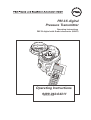
PM 3X digital Pressure Transmitter Operating instructions PM 3X digital with Smart electronics (HART) 0,753 Operating Instructions 9499-040-64311 Valid from: 8385 Short Operating Instructions PM 3X digital Short Operating Instructions Local operation with digital display Operation: – Function of the display Sect. 4.2 – Position and function of the operating elements on the electronic insert Sect. 4.1 Commissioning on site: – Sect. 5 Remote operation via HART protocol Operation: – with Commuwin II Sect. 4.4 – with Universal HART Communicator DXR 275 Sect.4.5 Commissioning with remote communication: – Sect.5.1 Software History Software version 1.0 2 Valid operating instructions (BA) 05.99 Device and Software No. Software revision 8010 – Changes in operating instructions – 9499-040-64311 PM 3X digital Table of Contents Table of Contents 1 Notes on Safety 1.1 Safety conventions 2 Introduction 3 Installation 3.1 3.2 3.3 3.4 Mounting instructions without diaphragm seal Mounting instructions with diaphragm seal Mounting accessories Electrical connection 4 Operation 4.1 4.2 4.3 4.4 4.5 Access to the operating elements Function of the display Position and function of the operating elements on the electronic insert Operation using Commuwin II Operating with the HART protocol via Universal HART Communicator DXR 271 5 Commissioning 5.1 5.2 5.3 5.4 On-site commissioning Commissioning and operation using communication Locking/Unlocking operation Information on the measuring point 6 Diagnosis and Troubleshooting 6.1 6.2 6.3 Diagnosis of errors and warnings Current simulation Reset 7 Maintenance and Repair 7.1 7.2 7.3 Repair Mounting the digital display Changing the gasket 8 Technical Data 9 Index 9499-040-64311 3 Notes on Safety PM 3X digital 1 Notes on Safety Approved usage The PM 3X digital is a pressure transmitter for measuring gauge or absolute pressure depending on the version. Mounting, commissioning, operation Explosion-hazardous area The PM 3X digital has been designed to operate safely in accordance with current technical, safety and EU standards. If installed incorrectly or used for applications for which it is not intended, however, it is possible that application-related dangers may arise, e.g. B. product overspill by incorrect installation or adjustment. For this reason, the instrument must be installed, connected, operated and maintained by personnel that are authorised by the user of the facility and who are suitably qualified. The manual must have been read and understood, and the instructions followed. Modifications and repairs to the device are permissible only when they are expressly approved in the manual. The measuring system used in the explosion-hazardous area must comply with all existing national standards. The instrument can be supplied with the following certificates as listed in the table. The certificates are designated by the first letter of the order code on the nameplate (see table below). Ensure that technical personnel are sufficiently trained. All measurement and safety regulations which apply to the measuring points are to be observed. Certificate for applications in explosion hazardous areas 4 Code Certificate Protection 0, 2, 4, 6 Standard none 1, 3, 5, 7 ATEX 100 ATEX II 1/2 G EEX ia IIC T6 9499-040-64311 PM 3X digital 1.1 Safety conventions In order to highlight safety-relevant or alternative operating procedures in the manual, the following conventions have been used, each indicated by a corresponding icon in the margin. Notes on safety Symbol Meaning Note! A note highlights actions or procedures which, if not performed correctly, may indirectly affect operation or may lead to an instrument response which is not planned. Caution! Caution highlights actions or procedures which, if not performed correctly, may lead to personal injury or incorrect functioning of the instrument. Type of protection Warning! A warning highlights actions or procedures which, if not performed correctly, will lead to personal injury, a safety hazard or destruction of the instrument. Device certified for use in explosion hazardous area If the device has this symbol embossed on its name plate it can be installed in an explosion hazardous area. Explosion hazardous area Symbol used in drawings to indicate explosion hazardous areas. Devices located in and wiring entering areas with the designation “explosion hazardous areas” must conform with the stated type of protection. Electrical symbols Safe area (non-explosion hazardous area) Symbol used in drawings to indicate, if necessary, non-explosion hazardous areas. Devices located in safe areas still require a certificate if their outputs run into explosion hazardous areas. Electric symbols Direct voltage A terminal to which or from which a direct current or voltage may be applied or supplied. Alternating voltage A terminal to which or from which an alternating (sine-wave) current or voltage may be applied or supplied. Grounded terminal A grounded terminal, which as far as the operator is concerned, is already grounded by means of an earth grounding system. Protective grounding (earth) terminal A terminal which must be connected to earth ground prior to making any other connection to the equipment. Equipotential connection (earth bonding) A connection made to the plant grounding system which may be of type e.g. neutral star or equipotential line according to national or company practice. 9499-040-64311 5 1 Introduction 9499-040-64311 2 Introduction Application The PM 3X digital pressure transmitter measures the pressure of gases, vapours and liquids and is used in all areas of chemical and process engineering. Operating principle Ceramic sensor The system pressure acts directly on the rugged ceramic diaphragm of the pressure sensor deflecting it by a maximum of 0.025 mm (0.0098 in). A pressure-proportional change in the capacitance is measured by the electrodes on the ceramic substrate and diaphragm. The measuring range is determined by the thickness of the ceramic diaphragm. Metal sensor The process pressure deflects the separating diaphragm with a filling liquid transmitting the pressure to a resistance bridge. The bridge output voltage, which is proportional to pressure, is then measured and processed. Ceramic sensor Metal sensor Ceramic substrate Resistance bridge Electrode Filling fluid Diaphragm Figure 1.1 Sensor construction Measuring system The complete measuring system consists of • PM 3X digital pressure transmitter with 4…20 mA signal output with superposed digital signal (HART communication) and • power supply 11.5…45 VDC, in Ex area 11.5…30 VDC. Operation can be carried out via: • a digital display for operating and calling up measured values locally, • the universal handheld HART Communicator DXR 275, • the Commuwin II operating program. PM 3X digital 4…20 mA Non-Ex area: 11.5…45 VDC Ex-i area: 11.5…30 VDC Process Figure 1.2 The measurement system 6 9499-040-64311 Mounting instructions without diaphragm seal Installation 3 Installation This section describes: • the mechanical installation of PM 3X digital with and without diaphragm seal, • the electrical connection. 3.1 Mounting instructions without diaphragm seal The PM 3X digital without diaphragm seal is mounted in the same way as a manometer. The use of shut-off valves and pigtails is recommended. The position depends upon the application. PM 3X digital without diaphragm seal – PM 31, 32 – PM 33, 34 • Measurement in gases: Mount the shut-off valve above the tapping point so that condensate can run back into the process. Figure 2.1 Mounting on a shut-off valve for measuring gases • Measurement in steam: Mount with a pigtail above the tapping point. The pigtail reduces the temperature in front of the diaphragm to almost ambient temperature. Before start-up, the pigtail must be filled with water. Figure 2.2 left: Mounting with U-shaped pigtail for measuring steam right: Mounting with circular pigtail for measuring steam 9499-040-64311 7 Mounting instructions without diaphragm seal PM 3X digital • Measurement in liquids: Mount on the shut-off valve below the tapping point or at the same height Figure 2.3 Mounting on a shut-off valve for measuring liquids The PM 33 with metal sensor is available in the following versions: Mounting the PM 33 Dimensions 1 in = 25.4 mm 1 mm = 0.039 in • with flush-mounted diaphragm or • with adapter and internal diaphragm. The adapter can be screwed on or welded in. A gasket is enclosed according to the material used and version. G ½ external with O-ring Welded nozzle Viton seal G ½ external Version 1F O-ring 14 x 1.78 Viton or NBR Screwed plug DIN 3852-E-G ½ Threaded hole DIN 3852-X-G ½ Teflon Figure 2.4 PM 33 with flush-mounted diaphragm above: G ½ external with O-ring below: G ½ external 8 Hastelloy Viton seal Teflon back-up PTFE seal 9499-040-64311 Mounting instructions with diaphragm seal Process connection flush-mounted diaphragm Welded Seal supplied With adapter internal diaphragm max. torque: 80 Nm Figure 2.6 PM 3X digital PM 33 with screwed or welded adapter. With screw adapter max. torque 80 Nm. 3.2 Mounting instructions with diaphragm seal The PM 3X digital with diaphragm seal is screwed in, flanged or clamped, depending on the type of diaphragm seal. PM 3X with screw cap PM 3X with flange PM 3X with clamp PM 3X digital with diaphragm seal – PM 35 – PM 36 Figure 2.5 Diaphragm seal versions • The protective cap of the diaphragm seal should only be removed just before mounting in order to protect the diaphragm. • The diaphragm of the diaphragm seal of the PM 3X digital must not be dented or cleaned with pointed or hard objects. • The diaphragm seal and the pressure sensor together form a closed and calibrated system which is filled with filling fluid through a hole in the upper part of the sensor. The following rules should be observed: − This hole is sealed and is not to be opened. − The instrument should only be turned by the diaphragm seal at the point provided and not by the housing. 9499-040-64311 9 Mounting instructions with diaphragm seal Mounting with temperature spacers PM 3X digital The use of temperature spacers is recommended for constant extreme product temperatures that can cause the maximum permissible ambient temperature of +85°C (+185°F) to be exceeded. • Note when mounting that the temperature spacer increases the maximum height by 100 mm (3.94 in). • Due to the water column in the temperature spacer, the increased height also causes a zero point shift of approx. 10 mbar (0.15 psi). Figure 2.8 Mounting with temperature spacers Mounting with capillary tubing Dimensions 1 in = 25.4 mm 1 mm = 0.039 in To protect from high temperature, moisture or vibration, or where the mounting point is not easily accessible, the housing of the PM 3X digital can be mounted with a capillary tube to one side of the measuring point. A bracket for mounting on a wall or pipe is available for this. Measuring point: – very moist – hot – strongly vibrating – difficult to access Mounting point away from the measuring point Figure 2.7 Mounting with capillary tubing and bracket away from the measuring point. Values in brackets apply to instruments with a raised cover. 10 9499-040-64311 Installation Mounting accessories 3.3 Mounting accessories PM 31 wall and pipe mounting with bracket Figure 2.9 Mounting with bracket left: on a vertical pipe right: on a wall. Values in brackets apply to instruments with a raised cover. PM 33 wall and pipe mounting with bracket Dimensions 1 in = 25.4 mm 1 mm = 0.039 in Figure 2.10 Mounting with bracket left: on a vertical pipe right: on a wall. Values in brackets apply to instruments with a raised cover. 9499-040-64311 11 2 Installation 9499-040-64311 3.4 Electrical connection Transposed, screened two-wire cabling is recommended for the connecting cable. Max. wire diameter: 2.5 mm2 permanently attached cable The power supply voltage is: • Non-Ex: 11.5…45 VDC • Ex i area: 11.5…30 VDC Internal protection circuits against reverse polarity, HF interference and overvoltage peaks (see TI 241F “EMC Guidelines”). A test signal can be measured using the terminal plugs for this purpose without interrupting measurement. Cable connection • Unscrew the cover • If present, remove the retainer ring with analogue display. In addition: –Push up the latch with the arrow until the grip of the retaining ring is audibly released. – Loosen the retainer ring carefully to prevent the display cable from breaking. The plug of the display can remain plugged in. • Insert the cable through the cable entry • Connect the cable wires as shown in the connection diagram. • Where appropriate, replace the retainer ring with analogue display. The grip of the retainer ring clips in with an audible click. • Screw down the cover Figure 2.11 Lifting off the display and removing the retaining ring To loosen the holder from the electronic insert, push latch with arrow upwards. Observe all local regulations for applications in the Eex i area! Ω Figure 2.12 Graph showing load 12 9499-040-64311 Electrical connection Installation Note! Terminal 3 on the electronic insert is for grounding and is already wired internally. If the connection cable has a screening or ground cable within it, then this may only be connected to the grounding terminal of the housing and not to Terminal 3 (see connecting diagrams). Test 4…20 mA Always connect the screening or ground cable (if present) to the internal ground terminal of the housing, not to Terminal 3. Plug Harting plug Plug M 12x1 9499-040-64311 Figure 2.13 Connection Plug assignment Terminal Function Wire colour code 1 2 8 + – PE Blue (BL) Brown (BN) Green-Yellow (GNYE) + – PE Red (RD) Black (BK) Green (GN) 13 Electrical connection PM 3X digital Connecting the handheld terminal • Do not replace the battery of the handheld terminal in the explosion hazardous area. • For a PM 3X digital with FM or CSA certificate: Electrical connection according to “Installation drawing” (enclosed in the packing of the PM 3X digital). • For correct transmission of the communication signal, a minimum resistance of 250 W must be present between the connection points and the power supply. any device Ω Figure 2.14 The handheld terminal can be connected anywhere along the 4…20 mA line. Connecting the Commubox FXA for operating with Commuwin II The Commubox FXA connects the PM 3X digital with a HART protocol to the RS 232 C serial interface of a personal computer. This enables the PM 3X digital to be remotely operated with the operating program. The Commubox FXA is used for intrinsically safe signal circuits. Figure 2.15 PC with Commuwin II Commubox FXA 14 minimum Total resistance 9499-040-64311 PM 3X digital Access to the operating elements 4 Operation This section describes: • Mounting the digital display • Function of the digital display • Position and function of the operating elements on the electronic insert • Operating via Commuwin II • Operating via the universal HART Communicator DXR 275 Contents 4.1 Access to the operating elements Lift display for operating The digital display is delivered already mounted when it is ordered with the instrument. In this case the digital display with the retaining ring must be removed before operating. If you want to order an digital display at a later date, then please observe the instructions in Section 6.3 “Mounting the digital display”. Removing the display: • Push up the latch with the arrow until the grip of the retaining ring on the electronic insert is heard to click. • Loosen the retainer ring and lift off carefully to prevent the display cable from breaking. • For reading the display during operation, plug the display onto the edge of the housing or let it hang down loosely by its cable next to the housing. To loosen the holder from the electronic insert push latch with arrow upwards. 9499-040-64311 Lifting off the display with retaining ring for operation. Figure 3.2 left: Loosing the holder right: Lifting off the display with retaining ring for operation 15 Function of the display PM 3X digital 4.2 Function of the display The digital display has two types of display: • Display in measurement mode: This is shown as standard • Display in calibration mode: This is shown after pressing the Zero or Span key once. It returns automatically to measurement mode after 2 seconds. Display in measurement mode 0,753 0,753 Display in calibration mode S Z 0,250 Figure 3.3 Function of the display 4.3 Position and function of the operating elements on the electronic insert Á Key for zero point calibration Ü Damping switch  Key for measuring span calibration Connection terminals for measuring the signal current Figure 3.4 Position of the operating elements Position of the Operating Elements No. 16 Operating element Function Ü Damping switch Switch position “off”: Damping 0 s Switch position “on”: Damping 2 s. This switch position also enables any damping to be entered between 0…40 s by remote communication e.g. with the handheld terminal. * Key for calibrating the zero point  press once: . . . . . . . press twice: . . . . . . . . . . . . . . . . . . . The acting pressure for the zero point is shown The acting pressure for the zero point is adopted Key for calibrating the measuring span * press once: . . . . . . . press twice: . . . . . . . . . . . . . . . . . . . The acting pressure for the measuring span is shown The acting pressure for the measuring span is adopted Key for calibrating the zero point and key for calibrating the measuring point press once simultaneously: The acting pressure is shown as the bias pressure press twice simultaneously: The acting pressure is adopted as the bias pressure 9499-040-64311 PM 3X digital Operation using Commuwin II 4.4 Operation using Commuwin II When operating using the Commuwin II display and operating program the PM 3X digital is calibrated and operated: • via an operating matrix or • via the graphics operating mode. The appropriate server (e.g. HART ) must be activated. A description of the Commuwin II operating program is found in the operating manual of commuwin. Operating matrix The advanced functions of the PM 3X digital can be accessed in this operating mode in the menu. • Each row is assigned to a function group. • Every field displays a parameter. The calibrating parameters are entered in the appropriate fields. Figure 3.5 Menu of instrument data in Commuwin II Graphics operation In this operating mode the calibration parameters for specific configuration procedures are entered in the appropriate box. Figure 3.6 Menu of instrument data in Commuwin II 9499-040-64311 17 Operation PM 3X digital 4.5 Operating with the HART protocol via Universal HART Communicator DXR 271 When operating with the HART protocol an interactive menu operation derived from the matrix is used (see also the appropriate operating manual for the handheld terminal). • The menu “Group Select” calls up the matrix. • The bar lines display the menu headings. • Parameters are set using submenus. LC display with menu text Function keys Keys for selecting Figure 3.7 left: Menu operation with the DXR 275 right: Universal HART Communicator DXR 275 handheld terminal Keys for entering parameters Connecting the handheld terminal is described in Section 2, page 12. The procedure for commissioning the measuring point with the Universal HART Communicator DXR 275 handheld terminal is described in Section 4 “Pressure Measurement”. 18 9499-040-64311 PM 3X digital On-site commissioning 5 Commissioning This section contains the following information: • On-site commissioning using keys on the electronic insert • Commissioning and operation using remote communication (Universal HART Communicator DXR 275 handheld terminal or Commuwin II) • Locking and unlocking the measuring point • Information on the measuring point Contents 5.1 On-site commissioning • Wire up the PM 3X digital (see Sect. 2.4 “Electrical connection”) • Connect a multimeter (4…20 mA) to the connection terminals provided. • Ensure that a pressure can be generated within the required measuring range. The damping t affects the speed with which the output signal and the digital display react to changes in pressure. A switch on the electronic insert is used for setting the damping: • Switch position off: Damping 0 s • Switch position on: Damping 2 s Preparatory work Damping Damping switch Figure 4.1 Position of the damping switch Key for setting the zero point Key for setting the measuring span Figure 4.2 Position of keys for adjust zero point and measuring span Adjustment of Zero is carried out by means of the pushbutton identified with Zero. Carry out the procedure as follows: • Provide the exact pressure for span start (Zero) at the pressure port. . • Push Zero button (Option ”digital display”, the presently stored Zero reference value is shown by the display). • Release Zero button, press again within 2 seconds and hold on pushing for 4 seconds. (Option ”digital display”, the ”Z”-symbol stops blinking).The pressure applied at the pressure port is taken as span start (Zero / 4 mA). Adjustment of Zero Adjustment of measuring span is carried out by means of the pushbutton identified with Span. Carry out the procedure as follows: • Provide the exact pressure for span end (20 mA) at the pressure port • Push Span button, (Option ”digital display”, the presently stored Span end reference value is shown by the display) The acting pressure for the measuring span is adopted. • Release Span button, press again within 2 seconds and hold on pushing for 4 seconds. (Option ”digital display”, the ”S”-symbol stops blinking). The pressure provided at the pressure port is taken as span end (Span / 20 mA) By pressing Zero- or Span pushbutton once, the presently stored reference values will be read accordingly. Adjustment of Measuring Span 9499-040-64311 19 Commissioning and operation using communication PM 3X digital 5.2 Commissioning and operation using communication Preparatory work • Wire up the PM 3X digital (see Sect. 2.4 “Electrical Connection”). • Decide which tool is to operate the PM 3X digital and wire it up accordingly. (Function Commuwin II see Sect. 3.4 , Function Universal HART Communicator DXR 275 see Sect. 3.5) Resetting to factory settings (Reset) By entering a code, the entries in the matrix are reset partially or completely to factory settings. Further information on the various types of reset and their effects are given in Section 5.3 “Reset”. # Matrix Moving through the menus Entry Main group: Transmitter information 1 Resetting to factory settings (Reset) V2H9 Damping äDefault values e.g. 2380 Enter The damping t affects the speed with which the output signal and the digital display react to changes in pressure. For setting the damping using the handheld terminal, the damping switch must be set to “on”. Values for damping between 0 and 40 s can be selected using the handheld terminal. # 1 Matrix Moving through the menus Damping switch Entry Set the damping switch to “on” Main group: Basic setting 2 Suppressing variations in the measured value V0H7 äDamping output τ=0…40 s e.g. 20 s Enter Jump Output signal τ τ τ Time Selecting the pressure units Selecting the pressure units determines in which units the pressure-specific parameters are to be shown. The pressure units available are given in the table below. After selecting new pressure units all information on the pressure are converted into the new units, e.g. 0…1 bar = 0…14.5 psi. # Matri x Moving through the menus Entry Main group: Basic setting 1 Selecting pressure units V0H 9 20 äSelecting pressure units e.g. psi Enter Units Units mbar kPa Units in H 2O kg / cm bar MPa ft H 2O kgf / cm atm Pa mm H2O psi hPa m H2O g / cm Units 2 Units 2 2 Torr mm Hg in Hg 2 lb / ft 9499-040-64311 PM 3X digital Commissioning and operation using communication The pressure required for zero point and span is calibrated using the handheld terminal without entering a reference pressure. # Matri x Moving through the menus Entry Lower and upper range value: calibration without reference pressure Enter zero point and measuring span Main group: Basic setting 1 Entering known pressure for zero point V0H 1 2 äSetting 4 mA e.g. 0 psi Enter Entering known pressure for span V0H 2 äSetting 20 mA e.g. 14.5 psi Enter No reference pressure A reference pressure is available that corresponds exactly to the zero point and span required. # Matri x Moving through the menus Entry Confirm zero point and measuring span Lower and upper range value: calibration with reference pressure Main group: Basic settings 1 Adopting the acting pressure for the zero point V0H 3 2 äConfirming 4 mA automatically e.g. 0 psi Enter Adopting the acting pressure for the span V0H 4 äConfirming 20 mA automatically Reference pressure e.g. 14.5 psi Enter If the display does not show zero after zero point adjustment (due to position), then this can be corrected to zero by entering a bias pressure or by adopting the bias pressure acting (depending on position). # Matri Moving through x the menus Bias adjustment Entry Main group: Basic setting 1 Setting the display to zero by entering a known bias pressure (pressure dependent on position). V0H 5 äSetting bias pressure e.g. 5 psi Enter alternatively 2 Setting the display to zero A bias pressure acting (pressure dependent on position) is adopted as zero pressure. V0H 6 äConfirming bias pressure automatically Enter The current signal is set to 3.8…20.5 mA as standard when operating correctly. Selecting the 4 mA level, ensures that a minimum current signal does not fall below 4 mA. # Matri x Moving through the menus 4 mA level (current output min. 4 mA) Entry Main group: Sensor data 1 V7H 3 äOff Current output min. 4 mA 9499-040-64311 e.g. On Enter 21 Commissioning PM 3X digital Output on error To indicate an error, an error code is transmitted with the measured value. At the same time the bargraph in the digital display assumes the value selected by the operator. The following values can be selected: • MIN: 3.6 mA • MAX: 22 mA • CONTINUE: measurement continued # Matri x Moving through the menus Entry Continued Main group: Basic settings 1 MIN. 3.6 mA Selecting output on error V0H 8 äSelecting fail-safe MAX. 22 mA e.g. MAX. Enter 5.3 Locking/Unlocking operation After calibrating or entering all parameters, the operation can be locked by entering a three-figure code other than 130. This blocks all fields and functions except V9H9 “Locking”. Locking is released by entering 130. # Matri Moving through x the menus Entry Main group: Service 1 Locking operation V9H 9 2 e.g. 131 Enter Releasing locking V9H 9 22 ä Locking ä Locking 130 Enter 9499-040-64311 PM 3X digital Commissioning 5.4 Information on the measuring point The following information on the measuring point can be called up with the handheld terminal: Matrix field Display or entry Measured values V0H0 Main measured value for pressure V7H0 Current display: Actual current in mA V7H8 Sensor pressure (units in V0H9) selectable V9H7 Actual dampened pressure without bias correction Sensor data V7H4 Lower calibration pressure V7H5 Upper calibration pressure V7H6 Lower measurement limit of sensor (units in V0H9 selectable) V7H7 Upper measurement limit of sensor (units in V0H9 selectable) Information on transmitter V2H2 8010 = Software number V2H7 Sensor data No.: Number of entry in the sensor table (1…10). Please remove from sensor pass V2H8 Sensor data value: Entry in sensor table, contains all sensor-specific data. Please remove from sensor pass Error response V2H0 Actual diagnostic code V2H1 Last diagnostic code Matrix field Display Communication level VAH0 Measuring point tag. The measuring point can be identified here with a max. of 8 characters. VAH1 Descriptor A max. of 16 characters can be entered here for the Descriptor. VAH2 User text A max. of 8 characters can be entered here. VAH3 Serial number of the transmitter VAH3 Serial number of the sensor 9499-040-64311 23 Diagnosis and Troubleshooting PM 3X digital 6 Diagnosis and Troubleshooting 6.1 Diagnosis of errors and warnings Error If the PM 3X digital identifies an error (E): • an error code is given and flashes on the digital display, • when a digital display is plugged in, the bargraph assumes the value selected for an error message (MIN, MAX, CONTINUE), • if the value displayed and the bargraph are flashing, • transmitter information can be read off in the main group or error codes read off in the matrix fields V2H0 and V2H1. Warning If the PM 3X digital identifies a warning (W): • an error code is given: the PM 3X digital continues to measure, • if the digital display is plugged in and the scale is flashing, • transmitter information can be read off in the main group or error codes read off in the matrix fields V2H0 and V2H1. Error codes in V2H0 and V2H1 If several codes occur simultaneously, the sequence in which they are displayed corresponds to their order of priority. Code Type Source and remedy E 101 Error Sensor Table check sum error – is shown e.g. when sensor parameters are being entered. . The error message disappears when the sensor parameters are entered . correctly and in full. E 103 Error Initialisation is being carried out – Wait until the procedure has been completed W 104 Warning Sensor calibration error (calibration points lie too near each other) – Recalibrate sensor E 106 Error Up/download active – Wait until the procedure has been completed E 115 Error Sensor overpressure – Remains until the overpressure disappears E 116 Error Download error – Restart download E 120 Error Sensor underpressure – Remains until the underpressure disappears W 613 Error Current simulation active – Remains until the simulation is completed, see also page 26 E 620 Warning Measured value outside initial value/final value 6.2 Current simulation If the function or certain reactions to connected evaluation instruments are to be checked, then a signal current can be simulated independently of the system pressure. # Matri x Moving through the menus Entry Main group: Additional functions 24 1 V7H 1 ä Simulation ON 2 V7H 2 ä Simulates current e.g. 22 mA 9499-040-64311 PM 3X digital Reset 6.3 Reset By entering a specific code, entries to the matrix can be reset either partially or fully. # Matri x Moving through the menus Entry Main group: Transmitter Info 1 V2H 9 ä Factory values e.g. 2380 The PM 3X digital differentiates between four types of reset with various responses. Which parameter is affected by which reset is given in the table below. H0 H1 H2 H3 H4 H5 V0 Sets 4 mA Sets 20 mA 4 mA automat. 20 mA automat. Sets bias pressure 5140 2380 731 2509 0.0 0.0 0.0 V7H7 V7H7 V7H7 deleted deleted deleted deleted 0.0 0.0 0.0 V2 Diagnostic code 0 0 0 Simulates current deleted Current min. 4 mA off off off Low and high sensor calibration The pressure delivered by the equation system is not corrected 5140 2380 2509 731 H6 Bias pressure autom. deleted H7 H8 H9 Dampens output Selects fail-safe Pressure unit 0.0 0.0 0.0 max. max. max. bar V3…V6 V7 Simulation off 5140 2380 2509 731 V8 V9 Locking 5140 2380 2509 731 130 VA 5140 2380 2509 731 Measurement point deleted deleted 9499-040-64311 Descriptor deleted deleted User text Serial number deleted deleted 25 Repair PM 3X digital 7 Maintenance and Repair 7.1 Repair If the PM 3X digital is to be sent to PMA GmbH Kassel for repair, then a note should be enclosed contining the following information. • An exact description of the application • The chemical and physical characteristics of the product. • A brief description of the error. Before sending in the PM 3X digital to PMA GmbH Kassel for repair, please take the following protective measures: • Remove all traces of the product. Thi is particularly important if the product is dangerous to health, e.g. corrosive, poisonous, carcinogenic, radioactive, etc. • We do request that no instrument should be returned to us without all dangerous material being completely removed first as it can, e.g. penetrate into fissures or diffuse through plastic. Caution! Instruments with certificates of conformity or design approval must be sent in for repair as complete units only. Note! In case of malfunction do not hesitate to contact our PMA-service. 26 9499-040-64311 9499-040-64311 Maintenance and Repair 7.2 Mounting the digital display The digital display is delivered already mounted when it is ordered with the instrument. In cases of damage, accessories can be ordered. • Push up the latch with the arrow until the grip of the retaining ring on the electronic insert is heard to click. • Loosen the retainer ring and lift off carefully to prevent the display cable from breaking. • Remove the plug of the display from the electronic insert. To loosen the holder from the electronic insert push latch with arrow upwards. Lifting off the display and removing the display • Insert the plug of the display in the jack in the electronic insert provided for this purpose and clip in Ü. Insert the pin on the retaining ring into the hole in the electronic insert provided for • this purpose *. • Firmly press down the retaining ring with the display onto the electronic insert. The stop makes an audible click. Removing the display Figure 6.1 left: Loosening the retaining ring right: Removing the display Mounting the display • À Á Figure 6.2 Mounting the display Changing the gasket PM 3X digital 7.3 Changing the gasket The gasket in contact with the medium and inside the process connection of the PM 3X digital can be replaced. Except for the PTFE gasket (Structure D), all gaskets can thus be interchanged as required. The different temperature limits should therefore be observed for individual materials. Gasket Temperature limits 1 FPM, Viton –20°C* (–4°F) 6 FPM, Viton grease-free –10°C* (+14°F) A FPM, Viton oil and grease-free for oxygen –10°C…+60°C (+14°F…+140°F) 2 NBR –20°C* (–4°F) 7 FFKM, Kalrez compound 4079 +5°C* (+41°F) 4 EPDM –40°C* (–40°F) * Upper temperature limit according to specifications of Changing the gasket • Loosen the screws on the retaining ring of the process connection. • Remove the retaining ring and process connection. • Replace gasket. The surfaces each side of the gasket and the gasket itself must be free from fibres and dirt. • Secure the process connection with the retaining ring and screws. 28 Gasket Replaceable process connection Figure 6.3 Changing the gasket Holding ring with screws 9499-040-64311 Technical Data PM 3X digital 8 Technical Data General information Manufacturer PMA Instrument Pressure transmitter Designation PM 31,PM 32, PM 33, PM 34, PM 35, PM 36 Technical documentation 9499-040-64311 Technical data PM 31 : 9498-737-38813 PM 32 : 9498-737-38913 PM 33 : 9498-737-39013 PM 34 : 9498-737-39113 PM 35 : 9498-737-39213 PM 36 : 9498-737-39313 Application Measurement of absolute and gauge pressure in gases, vapours, liquids Operation and system design Measuring principle PM 31, PM 32 with ceramic sensor The pressure causes a slight deflection of the ceramic diaphragm of the sensor. The change in the capacitance is proportional to the pressure and is measured by the electrodes of the ceramic sensor. Volume of chamber: approx. 2 mm 3 (0.078 in3) PM 33, PM 34, PM 35, PM 36 with metal sensor The process pressure acting on the metallic separating diaphragm of the sensor is transmitted via a filling fluid to a resistance bridge. The change in the output voltage of the bridge is proportional to the pressure and is then measured. Volume of chamber: smaller than 1 mm3 (0.039 in 3) Measuring system PM 3X digital and power supply e.g. via transmitter power pack and operation via –two keys on the instrument and a plug-in display module –DXR 275 handheld terminal –PC with the Commuwin II operating program via Commubox FXA Construction Aluminium- housing:PM31,PM33,PM36 Standard SS housing: PM32,PM34,PM35 for process connections see page 8 Signal transmission 4…20 mA signal with superposed HART communications signal, 2-wire detailed technical data see datasheet over internet http:// www.pma-online.de observably and/or to be downloaded can 9499-040-64311 29 PM 3X digital Page for notes 30 9499-040-64311 PM 3X digital Index 9 Index INDEX ! 4 mA level(current output) . . . . . . . . . . . . 21 A Actual dampened pressure without bias correction23 Adjusting the measuring span. . . . . . . . . . . 19 B Bias adjustment . . . . . . . . . . . . . . . . . . 21 Bias pressure . . . . . . . . . . . . . . . . . . . 25 C Cable connection . . . . . . . . . . . . . . . . . 12 Caution . . . . . . . . . . . . . . . . . . . . . . 26 Ceramic sensor . . . . . . . . . . . . . . . . . . . 6 Changing the gasket . . . . . . . . . . . . . . . 28 Commissioning . . . . . . . . . . . . . . 19, 22-23 Connecting the handheld terminal . . . . . . . . 14 Current simulation. . . . . . . . . . . . . . . . . 24 D Damping. . . . . . . . . . . . . . . . . . . . . . 19 Damping switch . . . . . . . . . . . . . . . . . . 16 digital display . . . . . . . . . . . . . . . . . . . 27 digital with diaphragm seal . . . . . . . . . . . . . 9 display . . . . . . . . . . . . . . . . . . . . . . . 15 E Electric symbols . . . . . . . . . . . . . . . . . . 5 electrical connection . . . . . . . . . . . . . . . . 7 Electrical connection . . . . . . . . . . . . . . 12-14 Error . . . . . . . . . . . . . . . . . . . . . . . . 24 Error codes . . . . . . . . . . . . . . . . . . . . 24 Explosion-hazardous are . . . . . . . . . . . . . . 4 F Function of the display . . . . . . . . . . . . . . 16 G gasket . . . . . . . . . . . . . . . . . . . . . . . 28 Graphics operation . . . . . . . . . . . . . . . . 17 M Maintenance . . . . . . . . . . . . . . . . . . 26-27 Measurement in Gases. . . . . . . . . . . . . . . 7 Measurement in liquids. . . . . . . . . . . . . . . 8 Measurement in steam. . . . . . . . . . . . . . . 7 Measuring principle . . . . . . . . . . . . . . . . 29 Metal sensor . . . . . . . . . . . . . . . . . . . . 6 Mounting accessories . . . . . . . . . . . . . . . 11 Mounting instructions . . . . . . . . . . . . . . 7-8 Mounting the display . . . . . . . . . . . . . . . 27 Mounting with capillary tubing . . . . . . . . . . 10 Mounting with temperature spacers . . . . . . . 10 N Notes on safety. . . . . . . . . . . . . . . . . . . 5 O On-site commissioning . . . . . . . . . . . . . . 19 operating elements . . . . . . . . . . . . . . . . 15 Operating matrix . . . . . . . . . . . . . . . . . 17 Operating principle . . . . . . . . . . . . . . . . . 6 Operation . . . . . . . . . . . . . . . . . . . 15, 18 Output on error . . . . . . . . . . . . . . . . . . 22 P power supply . . . . . . . . . . . . . . . . . . . . 6 R reference pressure . . . . . Removing the display . . . . Repair . . . . . . . . . . . . Reset . . . . . . . . . . . . Resetting to factory settings . . . . . . . . . . . . . . . . . . . . . . . . . . . . . . . . . . . . . . . . . . . . . . . 21 . . 15 . . 26 20, 25 . . 20 S Short operating instructions . . . . . . . . . . . . 2 Signal transmission . . . . . . . . . . . . . . . . 29 Software history . . . . . . . . . . . . . . . . . . 2 span . . . . . . . . . . . . . . . . . . . . . . . . 19 T H HART Communicator DXR 271 . . . . . . . . . . 18 Technical data . . . . . . . . . . . . . . . . . . . 29 Troubleshooting . . . . . . . . . . . . . . . . . . 24 I W Installation . . . . . . . . . . . . . . . . . . 7, 11-13 Warning . . . . . . . . . . . . . . . . . . . . . . 24 L Z Locking/Unlocking operation . . . . . . . . . . . 22 Zero point adjustment . . . . . . . . . . . . . . . 19 9499-040-64311 31 Subject to alterations without notice. Internet: www.pma-online.de BA 201O/94/EN / 06.06 71029853 CCS © PMA Prozeß- und Maschinen-Automation GmbH PO-BOX 310 229, D - 34058 Kassel Printed in Germany 9499 040 64311 (0606)c