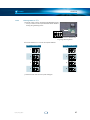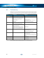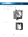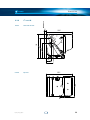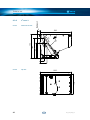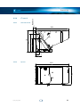
1
Operating Instructions
Coin Payout Hopper
with ccTalk interface and Multi-Drop commands (h2/xxxxx.xxF51..)
09.12 Bur/DVs/KQu/Roe
BA_h2_nano_F51_EN_2-1
Crane Payment Solutions GmbH | Zum Fruchthof 6 | 21614 Buxtehude | Germany
Web: [email protected] | www.craneps.com | Phone: +49 (0) 41 61-729-0 | Fax: +49 (0) 41 61-729-115
Table of contents
Table of contents
1
Revision protocol
6
2
General information
7
2.1
2.1.1
2.1.2
General information about these instructions
Text conventions
Additional useful technical documentation
7
7
7
2.2
General information about the hopper h2 nano/xxxxx.xxF51..
2.2.1
Features of the h2 nano/xxxxx.xxF51..
2.2.2
Scope of delivery
2.2.3Models
8
8
8
9
2.2.3.1
2.2.3.2
2.2.3.3
2.2.3.4
2.2.3.5
2.2.3.6
BA_h2_nano_F51_EN_2-1
Coin capacity (S/M/L/X)
Processing of extreme coin dimensions
Supply voltage
ccTalk product code
Full and empty detection
Mounting bracket
9
9
9
10
10
10
3
Safety instructions
11
3.1
Proper use
11
3.2
Protecting yourself and equipment
12
4Design
13
4.1
Overview of the device
13
4.2
Bowl and front bowl cover
14
4.3
Rotor, payout disc, and safety flap
14
4.4
Coin passage
14
4.5
Mounting bracket
14
4.6Interfaces
14
4.7
Status LEDs
15
4.8
4.8.1
4.8.2
Switching block of ...
15
2
... h /1 and higher
15
2
... h /015
3
Table of contents
5Function
16
5.1
Coin reception and payout
16
5.2
Payout control
16
5.3
Hopper control
16
5.4
Anti-jam function
16
5.5
5.5.1
Motor reverse after coins have been paid out
Timeout during payout (no coins found for payout)
17
17
5.6
Space-saving dual hopper assembly (coin passage)
18
5.7
5.7.1
5.7.2
5.7.3
Empty and full detection (option)
Empty detection
Full detection
ccTalk empty sensing (H217 Request payout high/low status)
18
18
18
18
6Start-up
19
6.1
6.1.1
6.1.2
6.1.3
Installing mounting bracket
Installing mounting bracket with spigots
Installing mounting bracket with large base plate
Aligning two hoppers with coin passage
20
20
20
21
6.2
Changing default settings (option)
22
6.3
Connecting hopper
22
6.4
Mounting and filling hopper
23
7Operation
24
7.1
7.1.1
7.1.2
24
24
25
7.1.2.1
7.1.2.2
Setting hopper address ...
... via ccTalk Multi-Drop Command Extension Set (MDCES)
... using hopper switching block
Selecting address on h2/1 and higher
26
Selecting address on h2/027
7.2
Setting payout speed (only h2/1 and higher)
28
7.3
Removing hopper
29
8
Maintenance and service
30
8.1
Cleaning hopper (every six months)
30
8.2Troubleshooting
4
32
BA_h2_nano_F51_EN_2-1
Table of contents
9
Technical data
33
9.1
Device data
33
9.2Interfaces
9.2.1
ccTalk machine interface
35
35
9.2.1.1
9.2.1.2
36
37
9.2.2
Implemented ccTalk commands
Communication example – Coin payout
Empty/full detection interface
9.3
Mounting dimensions
9.3.1h2 nano S
38
38
9.3.1.1
9.3.1.2
38
38
View from the side
Top view
9.3.2h2 nano M
39
9.3.2.1
9.3.2.2
39
39
View from the side
Top view
9.3.3h2 nano L
40
9.3.3.1
9.3.3.2
40
40
View from the side
Top view
9.3.4h2 nano X
41
9.3.4.1
9.3.4.2
41
41
View from the side
Top view
10Index
BA_h2_nano_F51_EN_2-1
37
42
5
1
Revision protocol
Version
Revision
_2-0
Adjustable hopper functions added: payout
timeout, ccTalk empty sensing
_2-1
Change of product name
(currenza h2 – h2 nano)
Chapters/sections concerned
4.5 "Motor reverse after coins have been
paid out"
4.7.3 "ccTalk empty sensing (H217 Request payout high/low status)"
All
General information
2
General information
2.1
This chapter should provide a general overview of the advantages and options regarding the
hopper h2 nano with ccTalk interface and Multi-Drop Command Extension Set (MDCES). The first
section, however, is designed to help you navigate easily within these operating instructions.
General information about these instructions
These operating instructions describe the design and operation of the NRI hopper h2 nano/
xxxxx.xxF51.. with ccTalk interface. Chap. 5 and 6 explain the necessary steps for starting up
and operating the hopper. Chap. 7 explicates how to clean the hopper and remedy the cause
of a malfunction.
Chap. 8 "Technical data" as well as the appended index reduce the search for specific explanation.
2.1.1
Text conventions
To make it easier for you to navigate within these instructions and to operate the device, the
following accentuations were made in the text:
2.1.2
Safety instructions, which you must observe in order to protect operators and equipment.
Special notes, which are to facilitate the use of the hopper.
At the beginning of a chapter you will find a short "guide", which summarises the
contents of the chapter.
1 2 3 ...
Requests to perform an action are numbered in another typeface.
[Fig. 1/2]
Reference to a figure. The number before the slash refers to the figure number,
the number behind the slash to the item number within the figure.
Additional useful technical documentation
Apart from the operating instructions you already have there is further documentation for the h2 nano,
e.g., about the firmware update. All documentation is available as PDF at www.nri24.com (a Download).
BA_h2_nano_F51_EN_2-1
7
General information
2.2
General information about the hopper h2 nano/xxxxx.xxF51..
The electromechanic hopper h2/xxxxx.xxF51.. is a coin payout system for machines. Depending
on the model size and the coin type it can collect 2,000 and more coins, in order to be able to
pay out these coins as change on command of the machine control system. Due to its high capacity the hopper is used in machines, that have to pay out certain coins as change frequently,
such as money changers, vending and amusement machines.
The h2/xxxxx.xxF51.. is fitted with a ccTalk machine interface and communicates with the control
system as slave using the serial ccTalk data transfer protocol including the Multi-Drop Command
Extension Set (MDCES) for unambiguous address handling.
The reliable and low-maintenance payout mechanism in the form of a rotating disc driven by a
motor is designed extra ruggedly, so that it withstands innumerous coin payouts permanently.
If the hopper is to be filled automatically, it can interact with a coin validation system without
any problems (e.g. NRI coin validators v2 colibri, G-13.mft, v2 eagle, G-40 or NRI coin changers
currenza c2 spider, E-66/A-66, G-46).
2.2.1
Features of the h2 nano/xxxxx.xxF51..
• Models in various sizes (S, M, L, X) for a coin capacity as high as possible depending on
the machine dimensions
• Space-saving dual hopper installation thanks to coin passage
• Suitable for paying out a wide range of coins with standard model
• Payout speed of up to 9 coins per second
• High performance and manipulation protection thanks to infrared payout control for
coins/tokens with any type of surface, automatic error detection and anti-jam function
• Unambiguous hopper address handling with MDCES
• Flash technology for uncomplicated and time-saving firmware updates using the NRI USB
flash programmer (ordering code 32446) and flash software "AT89USB_SPI" (freeware
and manual download at www.nri24.com)
• Optional empty and full detection
2.2.2
Scope of delivery
• Hopper h2/xxxxx.xxF51..
• Mounting bracket
8
BA_h2_nano_F51_EN_2-1
General information
2.2.3
Models
Most notably the hopper models differ in the
• coin capacity (S/M/L/X)
• processing of extreme coin dimensions
• supply voltage
• ccTalk product code
All models can be equipped with or without full or empty detection and be fixed onto two different mounting brackets depending on the machine dimensions.
2.2.3.1
Coin capacity (S/M/L/X)
The hopper capacity is defined by shape and depth of the bowl and the front bowl cover.
The four hopper sizes S, M, L, and X are made
up of two different sized bowls and two appropriate front covers for each bowl. The width
and the height of the hopper is always the
same (cp. Chap. "9.3 Mounting dimensions", p. 38).
The hopper size is embossed on the front
cover [Fig. 1/].
Hopper
Bowl
Cover
h2 nano S
small
S (short)
h nano M
small
M (long)
h2 nano L
large
L (short)
h2 nano X
large
X (long)
2
Fig. 1: h2 nano M with small bowl and long cover
2.2.3.2
Exchanging the front cover increases or decreases the hopper capacity.
Processing of extreme coin dimensions
Depending on the coin you would like to collect and its dimensions, you may need a hopper
purpose-made for, e.g., particularly thick or thin coins (cp. Chap. "9.1 Device data", p. 33):
2.2.3.3
• h2 nano standard
(Version 1.0)
• h2 nano standard for thin and small coins
(Version 1.1)
• h2 nano for thick coins
(Version 2.0)
Supply voltage
Depending on the machine evironment you may have a 12V or 24V hopper (up to model number
h2/0) or 11–35V hopper.
BA_h2_nano_F51_EN_2-1
9
General information
2.2.3.4
ccTalk product code
If the h2 nano is supposed to replace a G-38 hopper and the machine control system requires
a compatible ccTalk product code, the hopper may be delivered sending the "Payout" product
code (cp. Chap. "9.2.1.1 Implemented ccTalk commands", p. 36).
2.2.3.5
Full and empty detection
All hopper models are available with empty or full detection or with empty and full detection.
The detection is put into effect using electric contacts in the hopper bowl (not available for
retrofitting), which are closed by the coins from a certain filling level on or up to a certain filling
level (cp. Chap. "5 Function", p. 16).
2.2.3.6
Mounting bracket
Depending on the installation options
in the machine the hopper is either
delivered with a mounting bracket with
spigots or with a mounting bracket
with large base plate (cp. Chap. "6 Startup", p. 19).
Fig. 2: Mounting bracket with large base plate
(LH) and spigots (RH)
10
BA_h2_nano_F51_EN_2-1
Safety instructions
3
Safety instructions
Before operating the device for the first time, please read these operating instructions carefully
at least once, and most importantly the safety instructions. This is to ensure you have understood
the contents of this manual as well as how to operate the hopper.
3.1
Proper use
The NRI hopper h2/xxxxx.xxF51.. with serial ccTalk interface is intended to be used in machines
with a ccTalk interface and is supposed to collect coins accepted by the machine/coin validation
system or filled in the hopper and to pay them out as change on command of the machine control
system. Only use the hopper for this purpose. Under no circumstances can the manufacturer be
held liable for any damage or loss resulting from improper use of the device.
The hopper has been constructed in compliance with the state of the art and recognised safety
regulations. Nevertheless this equipment can be a source of danger. Therefore please observe
the following safety regulations.
BA_h2_nano_F51_EN_2-1
11
Safety instructions
3.2
Protecting yourself and equipment
The hopper may only be connected by a qualified electrician.
Only use the hopper according to proper use. Under no circumstances
can the manufacturer be held liable for any damage or loss resulting
from improper use of the device.
The hopper is not suited for outdoor use. For this it must be protected
using a housing/machine with an appropriate protection class.
The hopper PCB is fitted with components that can be damaged by
electrostatic discharge. Please observe the handling instructions for
components exposed to the risk of electrostatic discharge.
Do not use the hopper, if the device or connecting cable are demaged.
Select the correct voltage for the hopper (see label) and protect the
device against overheat demage caused by e.g. short-circuit or overload
by means of a 3A-fuse (according to IEC 127).
Never pull the connecting cable of the hopper from the machine when
a voltage is applied.
Pull out the machine’s mains plug before you install, clean or remove
the hopper.
Contact NRI if you wish to alter the construction of the device to a greater
extent than that described in these instructions.
Keep water and other liquids away from the hopper.
If the device is no longer required, please dispose of it correctly.
We reserve the right to make technical modifications to the device which
are not covered by these instructions!
12
BA_h2_nano_F51_EN_2-1
Design
4
Design
This chapter describes
• the main parts the hopper consists of, and
• all parts which you need to operate and start up the hopper.
4.1
Overview of the device
1
9
10
9
2
(covered)
8
3
11
7
12
4
(covered)
13
6
h2 nano M rear/left side
h2 nano M front/left side
1 Safety flap
2 Payout disc (covered)
3 Front bowl cover
4 Contacts of empty detection
5 Ejector lever, mounting bracket
6 Mounting bracket with spigots
7 Status LEDs (covered, visible through
housing)
8 Coin passage
12
14
15
16
h2/0M – service cover opened
9 Coin outlet
10 Bowl
12
11 Service cover
12 ccTalk interface – machine
13 Mounting stud
15
14
14 Switching block
15 Interface – Empty/full detection
16 For service technicians only
Fig. 3: Design (example: h2 nano M)
BA_h2_nano_F51_EN_2-1
h2/1M – service cover opened
13
Design
4.2
Bowl and front bowl cover
The bowl [Fig. 3/10] and bowl cover [Fig. 3/3] build the hopper funnel, which collects the coins,
in order to feed the rotating disc, that pays out the coins [Fig. 4/].
4.3
Rotor, payout disc, and safety flap
The payout disc [Fig. 4/] driven by a rotor directs the coins
from the bowl into the coin outlet [Fig. 3/9] by means of
metal pins inserted in the disc.
In order to protect the rotating parts against access during
operation and transport the coins optimally, the bowl is
provided with a safety flap [Fig. 3/1].
4.4
Coin passage
Fig. 4: Payout disc
The coin passage [Fig. 3/8] lets the coins paid out by an
additional hopper pass and thus serves as second coin outlet (cp. Chap. "5.6 Space-saving dual hopper
assembly (coin passage)", p. 18).
4.5
Mounting bracket
The mounting bracket [Fig. 3/6] [Fig. 5/] is used to install
the hopper in the machine (cp. Chap. "6 Start-up", p. 19). That
way the hopper may easily be removed and reinstalled.
Fig. 5: Mounting brackets
4.6
Interfaces
For detailed information on the serial ccTalk machine interface [Fig. 3/12] and on the connector
for the empty and full detection [Fig. 3/16] please refer to Chap. "9 Technical data", p. 33 (cp. Chap. "5.3
Hopper control", p. 16).
14
BA_h2_nano_F51_EN_2-1
Design
4.7
Status LEDs
The three status LEDs [Fig. 3/7] on the rear of the hopper indicate the operating state or a
malfunction):
Green LED
Hopper is receiving control signal and activates motor and payout
disc
Yellow LED
Hopper is paying out coin and transmits coin signal to control system
Red LED
Error, number of signals indicates error type (cp. Chap. "8.2 Troubleshooting", p. 32)
4.8
Switching block of ...
Depending on the hopper series the switching block [Fig. 3/14] has four or eight DIL switches
to set several functions (for details on how to use the switching block please refer to Chap. "7
Operation", p. 24):
4.8.1
... h2/1 and higher
Payout speed,
(cp. Chap. "7.2 Setting payout speed (only h2/1 and higher)", p. 28)
Hopper address,
(cp. Chap. "7.1.2 ... using hopper switching block", p. 25)
4.8.2
... h2/0
Hopper address,
(cp. Chap. "7.1.2 ... using hopper switching block", p. 25)
BA_h2_nano_F51_EN_2-1
15
Function
5
Function
This chapter describes the functional principle of the hopper:
• Coin reception and payout
• Payout control
• Hopper control
• Anti-jam function
• Space-saving dual hopper assembly (coin passage)
• Empty and full detection (optional)
5.1
Coin reception and payout
The coins of a particular type are either filled in the hopper bowl before starting up the hopper
or continuously sorted into the bowl by an upstream coin validation system. The funnel form
of the bowl and the safety flap direct the coins to the rotating payout disc uniformly. The disc
conveys the coins from the bowl via the coin outlet to the return area by means of metal pins
inserted in the disc.
5.2
The maximum coin payout speed of nine coins per second (standard) may be
reduced for, e.g., downstream coin validating systems using the switching block
(cp. Chap. "7.2 Setting payout speed (only h2/1 and higher)", p. 28).
Payout control
An optical sensor in front of the hopper‘s coin outlet reliably detects each coin paid out irrespective of its surface properties (plastic tokens, dark or opaque coins). This tamper-proof sensor
also prevents foreign objects from interfering or blocking the function of the sensor.
5.3
Hopper control
The control system communicates with the hopper using the serial ccTalk data transfer protocol.
For more details about the ccTalk protocol please refer to section Chap. "9.2 Interfaces", p. 35 and
the ccTalk specification at www.ccTalk.org.
5.4
Anti-jam function
The hopper detects, if the coins can no longer be transported due to a jam. In this case it changes
the rotational direction of the motor for 1.5s, so that the coins are splitt ed up on the transport
disc and can be paid out again when rechanging the rotational direction.
If the coin accumulation and pressure onto the payout disc is so high, that the motor can no
longer turn the disc, the rotational direction is changed for 0.5s and, if necessary, for further
full seconds until the jam has been removed.
16
BA_h2_nano_F51_EN_2-1
Function
5.5
Motor reverse after coins have been paid out
The hopper should be configured so that it stops turning the payout disc after the last coin has
been paid out during a transaction (default setting). If the "motor reverse function" is set to "1"
the motor turns backwards for 60ms. This may result in coin jams and may only be set if coins
getting stuck behind the ejector have to be removed.
5.5.1
For hopper configuration take note of the HopperTalk manual.
Timeout during payout (no coins found for payout)
If the hopper is empty and cannot find any coins which can be paid out, it changes the rotational
direction of the motor eight times. If this timeout is too long for some applications which switch
to other payout units or if the short cycles are sufficient, the hopper may be configured so that
the rotational direction will only be changed four times. The forward and backward cycle times
can be taken from the following diagrams:
Payout timeout [27,700ms]
1
tF1
tB1
2
tF1
tB1
3
tF1
tB1
4
tF1
tB1
5
tF1
tB2
6
tF1
tB2
7
tF1
tB2
8
tF1
tB2
tF1
t
Fig. 6: Long payout timeout (standard)
Payout timeout [19,900ms]
1
tF2
tB1
2
tF2
tB1
3
tF2
tB2
4
tF2
tB2
tF2
t
Fig. 7: Short payout timeout
tF1 = 2,100ms
tF2 = 3,100ms
tB1 = 600ms
tB2 = 1,600ms
BA_h2_nano_F51_EN_2-1
For hopper configuration take note of the HopperTalk manual.
17
Function
5.6
Space-saving dual hopper assembly (coin passage)
Thanks to the coin passage between the hopper’s rear cover and coin payout unit it is possible
to install two hoppers in the machine side by side and as close as possible.
If the hoppers are mounted accordingly, the coins paid out by the rear hopper can be directed
into the return area of the machine through the coin passage of the front hopper. In this case
the front hopper uses the coin passage as second coin outlet (cp. Chap. "6.1.3 Aligning two hoppers
with coin passage", p. 21).
5.7
Empty and full detection (option)
All hopper models can be equipped with an empty or with an empty and full detection.
5.7.1
Empty detection
The hopper uses the empty detection to signal the control system that the hopper must be
refilled in order to be able to pay out further coins.
The filling quantity is monitored by electric contacts in
the hopper bowl or bowl cover (cannot be retrofitted):
If the hopper is full, the electric circuit is closed by the
coins abutted on the contacts [Fig. 8/]. If the filling
level declines below one of the contacts, the circuit is
interrupted.
The empty detection is analysed by the hopper and
transmitted to the control system (Chap. "9.2 Interfaces",
p. 35 or ccTalk specification at www.ccTalk.org).
Fig. 8: Coins abutted on empty detection
5.7.2
Full detection
The hopper uses the full detection to signal the control system that no more coins can be fed
into the hopper, so that it does not overflow.
The filling quantity is also monitored by electric contacts in the hopper bowl or or bowl cover
(connot be retrofitted): If the filling level is below the contacts, no current flows. If it is as high
as the contacts, the electric circuit is closed by the coins abutted on the contacts.
The full detection is analysed by the hopper and transmitted to the control system (Chap. "9.2
or ccTalk specification at www.ccTalk.org).
Interfaces", p. 35
5.7.3
ccTalk empty sensing (H217 Request payout high/low status)
If the h2 nano is not supposed to send the empty signal according to the ccTalk specification
(H217 response: Bit0 = 1 = hopper empty), the hopper can be configured so that the machine
receives an inverted empty signal (Bit0 = 0 = hopper empty).
18
For hopper configuration take note of the HopperTalk manual.
BA_h2_nano_F51_EN_2-1
Start-up
6
Start-up
This chapter describes how to
• start up the hopper in a machine
• align tow hoppers with coin passage
For all installation work on the hopper or the machine please observe the following safety
instruction:
BA_h2_nano_F51_EN_2-1
The hopper may only be connected by a qualified electrician.
The hopper is not suited for outdoor use. For this it must be protected
using a housing/machine with an appropriate protection class.
Do not use the hopper, if the device or connecting cable are demaged.
Select the correct voltage for the hopper (see label) and protect the
device against overheat demage caused by e.g. short-circuit or overload
by means of a 3A-fuse (according to IEC 127).
Never pull the connecting cable of the hopper from the machine when
a voltage is applied.
Pull out the machine’s mains plug before you install or remove the hopper.
19
Start-up
6.1
Installing mounting bracket
The hopper is installed in the machine using the mounting bracket. Installation differs depending on the type of mounting bracket.
6.1.1
Please also compare the hopper's mounting dimensions in
dimensions", p. 38.
Chap. "9.3 Mounting
Installing mounting bracket with spigots
Install the mounting bracket in the machine
in consideration of the both underside spigots [Fig. 9/1] using four fixing screws and the
boreholes [Fig. 9/2] (Ø 4.2mm).
2
1
1
2
Fig. 9: Installing mounting bracket with spigots
6.1.2
Installing mounting bracket with large base plate
Install the mounting support in the
machine using four fixing screws and
either boreholes [Fig. 10/3] or [Fig. 10/4]
(Ø 4.2mm).
4
3
4
3
Fig. 10: Installing mounting bracket with large base plate
20
BA_h2_nano_F51_EN_2-1
Start-up
6.1.3
Aligning two hoppers with coin passage
26.1
If you want to install two hoppers and use
the coin passage, the mounting brackets
of the two hoppers must be installed in the
machine, so that the coin outlet of the one
hopper is aligned with the coin passage of
the other hopper [Fig. 11/]ff for mounting
bracket with spigots and section Chap. "6.1
Installing mounting bracket", p. 20).
8
Fig. 11: Aligning coin passage – top view
60°
.5
12
96.3
67.8
,64
32
11.1
27.6
Fig. 12: Aligning coin passage –
view from the side
BA_h2_nano_F51_EN_2-1
Fig. 13: Aligning coin passage –
spigots an coin passage dimensions
21
Start-up
6.2
Changing default settings (option)
If you want the hopper to operate with other DIL switch settings than ordered by you and set by
NRI and want to reconfigure the hopper address (default setting: 3) or payout speed using the
switches, it is advisable to change these settings before connecting and installing the hopper
(cp. Chap. "7 Operation", p. 24).
6.3
Connecting hopper
Depending on where the hopper(s) is/are to be installed in the machine, it is advisable to connect the hopper(s) first:
1 Disconnect the machine from the power supply.
2 Connect the hopper to the control system using the machine
interface on the rear of the hopper [Fig. 14/] and connecting cable.
Fig. 14: Machine interface
22
BA_h2_nano_F51_EN_2-1
Start-up
6.4
Mounting and filling hopper
1 Slightly tilt the hopper at the rear and use
its two mounting studs [Fig. 15/1] to slide
the hopper in the rear guides [Fig. 15/2] of
the mounting bracket.
3
2 Press the hopper into the mounting brack-
et, so that it engages behind the ejector
lever [Fig. 15/3] of the mounting bracket.
12
Fig. 15: Inserting hopper in mounting bracket
Make sure that the safety
flap of the hopper is installed
correctly and engaged in the
hopper bowl on both sides,
so that the rotating parts are
protected against access
during hopper operation and
the coins are transported to
the coin outlet optimally.
3 Fill the hopper with coins.
Fig. 16: Engaging safety flap
There are different hopper versions depending on the coins to be processed!
To guarantee a proper hopper operation,
please only fill those coins into the hopper intended for the corresponding hopper
version (see label specification V1.0, 1.1,
2.0 etc. as well as Chap. "9.1 Device data", p. 33,
keyword "Coin payout")!
V2.0
000323881804370012
V2.0
h /0X1C2.01U50S0X0400NX
2
ccTalk 11-35 V DC
09/12
CRANE PAYMENT SOLUTIONS GMBH
+49 (0) 41 61 / 729 - 0 * [email protected]
4 Reconnect the power supply to the machine.
BA_h2_nano_F51_EN_2-1
23
Operation
7
Operation
This chapter describes the operation, i.e. the setting of specific functions on the hopper itself:
• Selecting hopper address
• Setting payout speed (h2/1 and higher)
• Removing hopper
7.1
Setting hopper address ...
The default address of the hopper is 3. If you want to operate more than one hopper, the second
hopper must have another unambiguous address for error-free communication with the control unit.
The hopper address can be set via ccTalk MDCES (default setting) or using the hopper's switching block.
7.1.1
... via ccTalk Multi-Drop Command Extension Set (MDCES)
Upon delivery, the hopper switching block is set to "Address setting via ccTalk commands":
h2/1 and higher
h2/0
Fig. 17: DIL switch 5/4 set to "Address setting via ccTalk commands" (standard)
Applying the ccTalk Multi-Drop Command Extension Set (Headers 253–250) the hopper address
can be checked and changed (cp. Chap. "9.2.1.1 Implemented ccTalk commands", p. 36 and the ccTalk
specification for all datails).
24
BA_h2_nano_F51_EN_2-1
Operation
7.1.2
... using hopper switching block
Tools: Slotted screw driver, pointed object
If you want to use the switching block to set the hopper address (default setting: 3):
1 Turn the power off.
2 Detach hopper from mounting bracket
Chap. "7.3 Removing hopper", p. 29).
(cp.
3 Remove service cover (detach from the bottom
using a slotted screw driver, [Fig. 18/]) to gain
access to the switching block.
Fig. 18: Detaching service cover
Depending on the hopper series the DIL switches have different functions:
BA_h2_nano_F51_EN_2-1
25
Operation
7.1.2.1
Selecting address on h2/1 and higher
4 Set DIL switch 5 of the switching block [Fig. 19/1] toward
the top to ON to set the required address mode "Address
setting using switching block".
1
Fig. 19: DIL switch 5 set to "Address setting using switching block"
5 Use DIL switches 1 to 4 to set the required address:
Address
Switch setting
Address
3
11
4
12
5
13
6
14
7
15
8
16
9
17
10
18
Switch setting
6 Attach service cover and turn power ON again.
26
BA_h2_nano_F51_EN_2-1
Operation
7.1.2.2
Selecting address on h2/0
5 Set DIL switch 4 of the switching block [Fig. 20/1] toward
the top to ON to set the required address mode "Address
setting using switching block".
1
Fig. 20: DIL switch 4 set to "Address setting using switching block"
6 Use DIL switches 1 to 3 to set the required address:
Address
Switch setting
Address
3
7
4
8
5
9
6
10
Switch setting
7 Attach service cover and turn power ON again.
BA_h2_nano_F51_EN_2-1
27
Operation
7.2
Setting payout speed (only h2/1 and higher)
The payout speed can be set between 100 and 50% of the maximum speed of 9 coins/second
(standard setting).
Tools:
Slotted scew driver, pointed object
To set the payout speed in steps of approximately 7–8%:
1 Detach hopper from mounting bracket (cp. Chap. "7.3 Removing hopper", p. 29).
2 Remove service cover (detach from the bottom using a slotted screw driver, [Fig. 18/]).
3 Use DIL switches 6–8 of the switching block [Fig. 21/1] on
the rear of the hopper to set the required speed.
Payout speed
Switch setting
100% (9c/s)
1
93%
86%
Fig. 21: Switching block
79%
72%
65%
58%
50%
4 Attach service cover again.
28
BA_h2_nano_F51_EN_2-1
Operation
7.3
Removing hopper
It is very easy to remove the hopper from the mounting bracket:
1 Press the ejector lever [Fig. 22/1] down [A]
as far as its lips release the hopper.
2 Lift the hopper front [B] and disengage
the hopper from the guides [Fig. 22/2] of
the mounting bracket [C].
B
A
1
C
2
Fig. 22: Removing hopper
BA_h2_nano_F51_EN_2-1
29
Maintenance and service
8
Maintenance and service
In this chapter you will find out how to
• clean the hopper, and
• remedy the cause of a malfunction.
8.1
Please pull out the machine’s mains plug before you clean or maintain
the hopper.
Cleaning hopper (every six months)
The coins may leave residues on sensitive parts of the payout unit, when they are transported.
These residues must be removed from time to time, in order to guarantee a reliable hopper
operation:
• Cleaning interval:
every 500,000 payouts/six month
• Cleaning agent:
ethyl alcohol 96%, cotton bud/brush (with fine fibres, never metal),
cloth
Do not use any solvents or scouring agents which attack the plastic of
the device.
Do not submerge the hopper in any kind of liquid. This will damage the
device.
1 Pull the machine’s mains plug.
2 Pull the locking pinr [Fig. 23/1] of the safety
flap [Fig. 23/2] inwards and fold the flap upwards.
1
2
Fig. 23: Folding safety flap upwards
30
BA_h2_nano_F51_EN_2-1
Maintenance and service
3 Clean payout discr [Fig. 24/3] and all other parts, that are
contaminated by the coins, with a cloth/brush.
Under no circumstances may the cloth be
so wet that fluid runs into the device. Other
the hopper will be damaged.
4
3
4 Clean the sensor [Fig. 24/4]/[Fig. 25/4] using a cotton bud
with ethyl alcohol (access through coin outlet [Fig. 25/5]).
5 Let dry the damp parts for approx. 5 min.
6 Re-engage the safety flap.
7 Reconnect the machine to the mains supply.
Fig. 24: Parts to be cleaned
4
5
Fig. 25: Sensor access trough
coin outlet
BA_h2_nano_F51_EN_2-1
31
Maintenance and service
8.2
Troubleshooting
Malfunctions can occur in all electromechanic devices. These do not always have to be faults in
the device. In many cases the reason is improper connections or incorrect settings. Therefore:
please first of all check, whether the malfunction can simply be remedied using the following table.
Problem
Possible causes
Remedy, hints
Yellow LED flashing
Hopper is paying out a coin
No error
Red LED flashing
Hopper error:
1x
Coin payout sensor (after switch-on)
•covered by coin permanently
•Eliminate coin jam
•contaminated
•Clean sensor (cp. Chap. "8.1 Cleaning hopper
•defective
•Replace sensor (service case)
2x
Coin payout, although motor has not
been activated by control system
Prevent manipulation
3x
•Coin jam although rotational direc•Eliminate coin jam
tion has been changed several times
(anti-jam function)
(every six months)", p. 30)
6x
•Hopper empty: Although rotational
direction has been changed several
times, no coin has been paid out
•Refill hopper
Error, coin payout sensor
•Clean sensor (cp. Chap. "8.1 Cleaning hopper
(every six months)", p. 30)
•Check connection (service case)
•Replace sensor (service case)
7x (slow payout)
Coin outlet blocked
•Eliminate blockade
•Check outlet area
•Check/replace ejector assembly (service
case)
Hopper empty in spi- Connection error, contacts
te of empty detection
Connect contacts to the PCB correctly
(ccTalk hopper)
Hopper overflowed in
spite of full detection
Connect contacts to the PCB correctly
(ccTalk hopper)
Connection error, contacts
If the malfunction cannot be remedied, please contact our service technicians.
32
BA_h2_nano_F51_EN_2-1
Technical data
9
Technical data
This chapter contains information about
• all relevant hopper data
• the CE certification
• the machine and empty/full interfaces
• mounting dimensions
9.1
Device data
Supply voltageh2/1..: 11–35V DC
h2/0: 12/24V DC, ± 10%, 11–35V DC
Current consumption
Standby mode:
Inrush current, motor: approx.
Coin payout mode:
... with coins:
... without coins:
Electric strength
ccTalk: ccTalk data voltage
approx. 0.6W,± 10%
4A(h2/0: 3.5A), ± 10% (for approx. 75ms)
approx. 6W,± 40%
approx.4.8W,± 40%
Inputs/outputs
Temperature range
Operating temperature: 5 °C up to 50 °C
Storage temperature: -25 °C up to 70 °C
Temperature change
Max. 0.2 °C/min.
Rel. humidity
10% up to 90%
Condensation
Not permitted
Machine interface
10-pole terminal strip (standardised)
9600 baud, 8-bit, N, 1, 1, 5 V TTL, common transmitting and receiving line,
active low
Protocol according to ccTalk 4.2, Money Controls (cp. Chap. "9.2.1.1 Implemented
ccTalk commands", p. 36)
For pin assignment see Chap. "9.2 Interfaces", p. 35
BA_h2_nano_F51_EN_2-1
33
Technical data
Coin payoutSpeed:
average of 7 coins/s
max.
9 coins/s
Coin diameter: 18.5–26.5mm (standard version and 1.1)
Coin thickness:1.6–2.6mm (standard version and 1.1)
Diameter (mm)
30
28
26
2.- EUR
24
22
0.05 EUR
20
0.50 EUR
1.- EUR
0.20 EUR
0.10 EUR
18
16
14
1.3 1.4 1.5 1.6 1.7 1.8
Thickness (mm)
1.9 2.0 2.1
2.2
2.3 2.4 2.5 2.6 2.7 2.8
2.9 3.0 3.1 3.2 3.3
3.4
Version 1.0: h2 nano standard
Version 1.1: h2 nano standard for thin and small coins
Version 2.0: h2 nano for thick coins
(cp. Chap. "2.2.3 Models", p. 9)
Maximum capacity
Ø22.25
(2.14 thick)
(20c)
Ø24.25
(2.38 thick)
(50c)
Ø25.75
(2.20 thick)
(€2)
h2 nano S
300
230
230
200
h2 nano M
570
440
450
370
h nano L
700
530
550
520
h2 nano X
920
710
680
620
2
Dimensions
Ø23.25
(2.33 thick)
(€1)
Height:154.0
Width:131.4
Depth, h2 nano S: 115.5
Depth, h2 nano M:154.5
Depth, h2 nano L: 186.3
Depth, h2 nano X: 225.3
(cp. Chap. "9.3 Mounting dimensions", p. 38)
Weighth2 nano S: 650g
h2 nano M:680g
h2 nano L: 680g
h2 nano X: 700g
Mounting position
Vertical, max. deviation: ± 3°
Directives appliedEMC:2004/108/EC
EN 55 014-2 (interference resistance)
EN 55 022 (interference emission)
Machinery:2006/42/EC
R&TTE:
1999/5/EC (Radio and telecommunication terminal equipment)
(cf. Declaration of Conformity)
34
BA_h2_nano_F51_EN_2-1
Technical data
9.2
Interfaces
On the following pages you will find information for connecting the hopper to the machine:
• Pin assignment of machine and empty/full detection interface
• Implemented ccTalk commands
9.2.1
ccTalk machine interface
Pin no. Function
BA_h2_nano_F51_EN_2-1
1
ccTalk data
2
V DC
3
V DC
4
GND
5
GND
6
GND
7
V DC
8
GND
9
n.c.
10
V DC
2
10
1
9
35
Technical data
9.2.1.1
Implemented ccTalk commands
Header Name
Simple poll
253
Address poll
(checking address ambiguities)
252
Address clash
(Polling slave devices sharing same
address)
251
Address change
(Changing a particular ambiguous
address)
250
Address random
(Randomise slave device addresses)
246
Request manufacturer ID
"NRI"
245
Request ID
"Payout"
244
Request product code
242
Request serial number
"CURRENZA H2"/"Payout"
(cp. Chap. "2.2.3.4 ccTalk product code", p. 10)
241
Request software version
236
Read opto states
219
Enter new PIN number
218
Enter PIN number
217
Request payout high/low status
Empty signal according to ccTalk specification or
inverted empty signal
192
Request build code
"Combo"
172
Emergency stop
169
Request address mode
168
Request hopper dispense count
167
Dispense hopper coins
166
Request hopper status
164
Enable hopper
163
Test hopper
160
Request cipher key
4
Request comms revision
1
Request device
36
Data transmitted by hopper
254
"437.nn"
SCH1 format
(cp. specification, "Format (b)")
SCH1 format
(cp. specification, "Format (a)")
"145"
For more details please refer to the ccTalk specification (www.cctalk.org).
BA_h2_nano_F51_EN_2-1
Technical data
9.2.1.2
Communication example – Coin payout
1 Check the hopper status by sending the TEST command:
Command: 03 00 01 A3 59
Response: 01 01 03 00 80 FA
The hopper is disabled.
2 Enable the hopper by sending the ENABLE command:
Command: 03 01 01 A4 A5 B2
Response: 01 00 03 00 FC
Optionally a new TEST command can be issued to verify the status of the hopper.
3 Request the CIPHER KEY from the hopper by sending the REQUEST CIPHER KEY command:
Command: 03 00 01 A0 5C
Response: 01 08 03 00 B9 FE 5F AC 75 0A 7B 98 A0
4 Start the payout of 3 coins [03] by sending the DISPENSE COINS command together with
the CIPHER KEY:
Command: 03 09 01 A7 63 D9 2A 95 BA D4 35 82 03 09
Response: 01 00 03 00 FC
The hopper ACKs the command.
5 During the payout, check the number of remaining coins every 100ms with the REQUEST
HOPPER STATUS command:
Command: 03 00 01 A6 56
Response: 01 04 03 00 02 00 03 00 F3
From the response can be seen that
•2 dispense commands have been sent
•0 coins are remaining
•3 coins have been paid
•0 coins are unpaid.
Once the number of remaining coins is 0, the polling may be stopped and the payout can
be verified.
6 Check the hopper status by sending the TEST command:
Command: 03 00 01 A3 59
Response: 01 01 03 00 00 7A
From the status bytes can be seen that no payout timeout, opto blockings or coin jams
have occured.
9.2.2
Optionally the payout can be verified by checking the coins paid, unpaid and
total dispense counters using the REQUEST HOPPER STATUS.
Empty/full detection interface
Pin no. Function
BA_h2_nano_F51_EN_2-1
1
Full
2
Empty
3
GND
37
9.3
Mounting dimensions
9.3.1
h2 nano S
9.3.1.1
View from the side
Machine wall
Technical data
15
115.5
6
33.4
128.2
99.2
154
t
60°
utle
no
Coi
27
43.7
Top view
115.5
131.4
9.3.1.2
38
BA_h2_nano_F51_EN_2-1
9.3.2
h2 nano M
9.3.2.1
View from the side
Machine wall
Technical data
15
154.5
6
128.2
99.2
154
60°
let
out
33.4
in
Co
27
43.7
Top view
154.5
131.4
9.3.2.2
BA_h2_nano_F51_EN_2-1
39
9.3.3
h2 nano L
9.3.3.1
View from the side
Machine wall
Technical data
15
186.3
6
60°
99.2
128.2
154
let
out
33.4
in
Co
27
43.7
Top view
186.3
131.4
9.3.3.2
40
BA_h2_nano_F51_EN_2-1
9.3.4
h2 nano X
9.3.4.1
View from the side
Machine wall
Technical data
15
225.3
6
60°
128.2
99.2
154
let
out
33.4
in
Co
27
43.7
Top view
225.3
131.4
9.3.4.2
BA_h2_nano_F51_EN_2-1
41
Index
10
Index
A
Accentuations in the text 7
Address, ccTalk hopper 26, 27
Adjustments 24
Advantages 8
Angle, mounting position 34
Anti-jam function 16
Application, proper 11
Applied directives 34
AT89USB_SPI flash programmer 8
B
Bowl 9, 13
front cover 9, 13, 14
Bracket 13
C
Capacity, maximum 34
Cascade assembly 18
ccTalk
commands 36
data transfer protocol 16
Chapter summary 7
Cleaning
hopper 30
sensor 30
Coin
diameter 34
euro coins 34
jam 16
outlet 13, 14
passage 13, 14, 18
payout 16
sensor, clean 30
speed 16, 34
reception 16
thickness 34
euro coins 34
Commands, ccTalk 36
Components 13
Condensation 33
Connection 19
empty/full contacts 37
hopper 22
42
Connector assignment
ccTalk machine interface 35
Empty/full detection 37
Contacts
empty detection 18, 37
full detection 18, 37
Container 14
Control 16
Cover 9, 13, 14
Current consumption 33
D
Design 13
Deviation, mounting position 34
Device dimensions 34
DIL switches
set hopper address 25
set payout speed 28
Dimensions 34, 38
Directives, applied 34
Disc 13, 14
Discharge, electrostatic 12
Dismounting hopper 29
Documentation, additional 7
Dual hopper assembly 18
E
Ejector lever 13
Electric strength 33
Electrostatic discharge 12
EMC directive 34
Empty/full detection 13
interface 13, 37
pin assignment 37
using bowl contacts 18
Error remedy 32
Euro coins
diameter 34
thickness 34
BA_h2_nano_F51_EN_2-1
Index
F
M
Firmware update 8
Flap 13, 14
Flash programmer (firmware update) 8
Full/empty detection 13
interface 13, 37
pin assignment 37
using bowl contacts 18
Function 16
Funnel 9, 13, 14
front cover 9, 13, 14
Machine interface 13, 14, 33, 35
Machinery directive 34
Main parts 13
Maintenance 30
Manipulation protection 16
Manuals, additional 7
Markings in the text 7
Maximum capacity 34
Measures 33, 38
M hopper 9
Models 9
Motor 14
change rotary direction 16
Mounting
bracket 13, 14
dimensions 33, 38
hopper 23
mounting bracket 20
position 34
stud 13
two hoppers 21
G
General information
hopper 8
manual 7
Guide, chapter contents 7
H
Handling 24
Hopper
clean 30
dismount 29
Humidity 33
N
I
Notes 7
Inrush current 33
Installation 19
hopper 22, 23
mounting bracket 20
two hoppers 21
Instructions, additional 7
Interface 13, 14, 33, 35
Internet address, NRI 7
Introduction
chapter 7
hopper 8
manual 7
O
J
Jam 16
L
LEDs 13, 15
troubleshooting 32
L hopper 9
Lid 13, 14
BA_h2_nano_F51_EN_2-1
Operating
instructions, additional 7
voltage 33
Operation 24
P
Parts 13
Payout 16
control 16
disc 13, 14
sensor, clean 30
speed 16, 34
set 28
Pictograms in the text 7
Pin assignment
ccTalk machine interface 35
empty/full detection 37
Power
consumption 33
supply 33
Proper use 11
43
Index
R
T
Relative humidity 33
Remove hopper 29
Requests to perform an action 7
Rotor 14
cover 13, 14
R&TTE directive 34
Technical data 33
Temperature
change 33
range 33
Tilt, mounting position 34
Transport disc 13, 14
Troubleshooting 32
Types 9
S
Safety
flap 13, 14
instructions 7, 11
Scope of delivery 8
Sensor (coin outlet) 16
clean 30
Service 30
cover 13
Settings 24
S hopper 9
Speed, coin payout 16, 34
set 28
Start-up 19
Status LEDs 13, 15
troubleshooting 32
Summary, chapter 7
Supply voltage 33
Support 14
Switching block 13, 15
set hopper address 25
set payout speed 28
Symbols in the text 7
44
U
Use, proper 11
V
Variants 9
Versions 9
W
Website, NRI 7
Weight 34
www.nri24.com 7
X
X hopper 9
BA_h2_nano_F51_EN_2-1