1
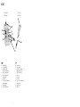
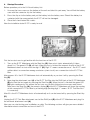
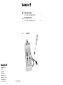
GB
IE-CT
Weidmüller Interface
GmbH & Co. KG
Postfach 3030
32720 Detmold
Telefon +49 5231 14-0
Telefax +49 5231 14-2083
[email protected]
www.weidmueller.com
012005/50/01/BTR/899006-01
Bedienungsanleitung
IE-CT Kabel- und Installationstester
3
Operating instructions
IE-CT Cable and Installation Tester
15
8808420000
IE-CT
IE-CT Grundgerät
IE-CT Mainframe
IE-CT Testbox
IE-CT Test Box
K
F
B
E
G
C
D
H
I
J
A
GB
A =
B =
C =
D
E
F
G
H
I
J
K
=
=
=
=
=
=
=
=
Anschlussleitung
7-Segmentanzeige
neun Einstellschalter
(unter dem Schutzgummi)
Ein-/Aus- und Starttaste
RJ45-Anschlussbuchse
neun rote LEDs
grüne LED
Step-Taste zur Fehlerabfrage
Fehlerbeschreibung
Anschlussleitung
RJ45-Anschlussbuchse
A =
B =
C =
D
E
F
G
H
I
J
K
2
=
=
=
=
=
=
=
=
attachment cord
numeric display
nine Selection Switches
(under protective cover)
ON/OFF and Start Key
RJ45 jack
nine red LED
green LED
Step Key for error interrogation
error description
attachment cord
RJ45 jack
Contents
1.
GB
Introduction . . . . . . . . . . . . . . . . . . . . . . . . . . . . . . . . . . . . . . . . . . . . . . . . . . . . . . . . . . . . . . 16
1.1
Contents of Packing Unit . . . . . . . . . . . . . . . . . . . . . . . . . . . . . . . . . . . . . . . . . . . . . . . . 16
2.
Safety Instructions . . . . . . . . . . . . . . . . . . . . . . . . . . . . . . . . . . . . . . . . . . . . . . . . . . . . . . . . . 16
3.
Features . . . . . . . . . . . . . . . . . . . . . . . . . . . . . . . . . . . . . . . . . . . . . . . . . . . . . . . . . . . . . . . . . 17
4.
Startup Procedure . . . . . . . . . . . . . . . . . . . . . . . . . . . . . . . . . . . . . . . . . . . . . . . . . . . . . . . . . 18
5.
Operation . . . . . . . . . . . . . . . . . . . . . . . . . . . . . . . . . . . . . . . . . . . . . . . . . . . . . . . . . . . . . . . . 19
5.1
Connection to Test Installation Lines . . . . . . . . . . . . . . . . . . . . . . . . . . . . . . . . . . . . . . . . 19
5.2
Connection to Test Patch Cables . . . . . . . . . . . . . . . . . . . . . . . . . . . . . . . . . . . . . . . . . . 19
5.3
Switch on and Test . . . . . . . . . . . . . . . . . . . . . . . . . . . . . . . . . . . . . . . . . . . . . . . . . . . . . 20
5.4
Line Identification . . . . . . . . . . . . . . . . . . . . . . . . . . . . . . . . . . . . . . . . . . . . . . . . . . . . . . 21
5.5
Selection of Contact Assignment . . . . . . . . . . . . . . . . . . . . . . . . . . . . . . . . . . . . . . . . . . 21
5.6
Extraneous Voltage (Error Code 1) . . . . . . . . . . . . . . . . . . . . . . . . . . . . . . . . . . . . . . . . . 22
5.7
Connection Error (Error Code 2) . . . . . . . . . . . . . . . . . . . . . . . . . . . . . . . . . . . . . . . . . . . 22
5.8
Conductor Interrupt (Error Code 3) . . . . . . . . . . . . . . . . . . . . . . . . . . . . . . . . . . . . . . . . . 22
5.9
Short Circuit (Error Code 4) . . . . . . . . . . . . . . . . . . . . . . . . . . . . . . . . . . . . . . . . . . . . . . . 22
5.10 Wrong Wiring (Error Code 5) . . . . . . . . . . . . . . . . . . . . . . . . . . . . . . . . . . . . . . . . . . . . . . 23
5.11 Switch Setting (Error Code 6) . . . . . . . . . . . . . . . . . . . . . . . . . . . . . . . . . . . . . . . . . . . . . 24
5.12 Battery (Error Code 7) . . . . . . . . . . . . . . . . . . . . . . . . . . . . . . . . . . . . . . . . . . . . . . . . . . . 24
5.13 Split pair (Error Code 8) . . . . . . . . . . . . . . . . . . . . . . . . . . . . . . . . . . . . . . . . . . . . . . . . . . 24
6.
Error Indication . . . . . . . . . . . . . . . . . . . . . . . . . . . . . . . . . . . . . . . . . . . . . . . . . . . . . . . . . . . . 25
7.
Intermittent contact . . . . . . . . . . . . . . . . . . . . . . . . . . . . . . . . . . . . . . . . . . . . . . . . . . . . . . . . 26
8.
Self-test . . . . . . . . . . . . . . . . . . . . . . . . . . . . . . . . . . . . . . . . . . . . . . . . . . . . . . . . . . . . . . . . . . 26
9.
Technical Data . . . . . . . . . . . . . . . . . . . . . . . . . . . . . . . . . . . . . . . . . . . . . . . . . . . . . . . . . . . . 27
10. Guarantees and warranties . . . . . . . . . . . . . . . . . . . . . . . . . . . . . . . . . . . . . . . . . . . . . . . . . . 27
15
1.
Introduction
By purchasing the installation tester IE-CT you have decided to opt for an easy and professional
piece of test equipment that is easy to use. This tester is designed for quick and reliable recognition
of installation faults in data and telecommunication wiring.
IE-CT includes two devices – IE-CT Mainframe and IE-CT Test Box.
The number of conductors of the cable installation and the pin assignment can be set individually.
Please read this user manual carefully before using the installation tester IE-CT for the first time.
The housing of the IE-CT Mainframe shows the most important information for fault analysis.
1.1 Contents of Packing Unit
Please check the contents of the IE-CT packing:
•
•
•
•
•
•
•
•
Installation tester IE-CT Mainframe
Installation tester IE-CT Test Box No 1
Attachment cord for the IE-CT Mainframe
9 V battery
User manual
Protective bag
Label with english description
Label with french description
Important! Please keep this user manual, it contains important information about function,
putting into operation and handling of the device. Please consider this, too, when leasing or
passing it on to third.
2.
Safety Instructions
•
Protect the IE-CT against humidity and moisture as well as against temperatures below 0 °C (32 °f)
or above 40 °C (90 °f).
Clean the housing only with a humid cloth, do not use any aggressive cleaning agents.
Repairs on the IE-CT shall be done exclusively by Weidmüller.
Use only 9 V block batteries or rechargeable batteries.
When opening the IE-CT housing for battery change do not touch any components or the pc
board.
Use only original replacement parts from Weidmüller.
Protect the IE-CT against strong vibrations and shocks.
Do not overbend the attachment cords.
Always close the selection switches with the protective cover and do not allow any parts to fall into
the opening.
Do not press the switches harder than necessary.
Take out the battery if the IE-CT will not be used for some time.
•
•
•
•
•
•
•
•
•
•
Warranty will expire in case of non-observance of this user manual and/or the safety
instructions and in case of inappropriated handling! We decline liability for any consequential
damages!
16
3.
Features
•
Recognition and display of the most frequent installation errors:
short circuit, line/wire interrupt, line/wire mistakes, split pair
•
Self test function and intermittent contact test
•
Error display for each conductor by eight red conductor LED’s and one red LED for the shield (F).
•
Display of no error by green LED (G).
•
One key for ON, OFF and start of the test operation (D).
•
Separate Step Key (H) to display list of multiple errors.
•
Automatic shut off of the IE-CT 30 seconds after the last use of key D or H.
•
Nine switches define the pin assignment (C).
•
Numeric display shows error type (B).
•
9 conductor attachment cord (A) for testing shielded installation lines and cables with up to 8
conductors.
•
IE-CT Mainframe and IE-CT Test Boxes are equipped with RJ45 jacks (E and K) allowing also test
of patch cords.
•
Protected against interference voltages up to 80 V AC/DC (100 V up to 5 minutes).
•
Display of extraneous voltages for each conductor including readout of their polarity.
•
Easy use and interpretation of the test results with given help on the IE-CT housing (I).
•
Display for low battery power.
•
Length of installation cable to be tested up to 1000 m.
•
Automatic test operation is shown by flashing LED (G).
•
Battery polarity reversal protection.
•
Line identification by recognition of up to nine test boxes.
•
Recognition and display for wrong set of pin assignment.
•
Low power consumption for long battery life.
17
4.
Startup Procedure
Before operation put in the 9 V block battery first.
1.
Unscrew the two screws on the bottom of the unit and take this part away. You will find the battery
case with the connector clip for the battery.
2.
Press the clip on to the battery and put the battery into the battery case. Should the battery be
contacted with the wrong polarity the IE-CT will not be damaged.
3.
Close the lid and fasten the screws.
Now the installation tester IE-CT is ready for use!
First do two test runs to get familiar with the functions of the IE-CT:
1.
Turn on the IE-CT Mainframe with the Start Key (D). Now a test starts automatically (it takes
about 3 s). The green LED (G) will flash. When the test is finished the numeric display of the IE-CT
Mainframe shows as test result the digit “2” (B). Digit “2” means connection error – the IE-CT could
neither detect a connection among conductors (short circuit) nor a connection to the IE-CT Test
Box.
After approx. 30 s the IE-CT Mainframe shuts off automatically or you turn it off by pressing the Start
Key (D).
2.
Now plug the attachment cord (J) of the IE-CT Test Box into the RJ45 jack of the IE-CT Mainframe
(E) and start the test again by pressing the Start Key (D). When the test is finished the green LED
(G) lights continuously, this means the test was successfully finished and no errors were found.
Now press the Step Key (H), the numeric display (B) of the IE-CT Mainframe will show the number
of the connected IE-CT Test Box by a flashing digit (flashing digit “1” means “IE-CT Test Box No 1”
is connected).
After 30 s the IE-CT Mainframe shuts off automatically or it can be turned off by pressing the Start Key
(D).
Unplug the IE-CT Test Box attachment cord of the RJ45 jack (E) of the IE-CT Mainframe and plug it in
the enclosed attachment cord (A).
Now you can start testing your installation or cable. The following sections will give you more detailed
information about connection and use of the IE-CT.
18
5.
Operation
5.1 Connection to Test Installation Lines
To test an installed line plug one end of the installation line to the IE-CT Mainframe and the other end to
the IE-CT Test Box.
To do a simultaneous line identification plug one IE-CT Test Box to each termination to be tested
(max. 9 Test Boxes, available as accessories).
Installation Lines
Patch Panel
Wall Outlets
IE-CT Test Boxes
IE-CT Mainframe
5.2 Connection to Test Patch Cables
Patch Cable
If you want to use the IE-CT for error detection on
patch cables, plug one end of the patch cable into
the RJ45 jack of the IE-CT Mainframe and the other
end into the RJ45 jack of the IE-CT Test Box.
19
5.3 Switch on and Test
Terminate IE-CT Mainframe and IE-CT Test Box, then start the installation test and line identification as
shown below.
% Press the Start Key (D) to turn on the
IE-CT Mainframe.
press Start Key
# During the test run, the green LED (G) flashes. The
test is finished when the green LED stops flashing.
The green LED flashes
$ The green LED (G) lights without interruption if no
errors were detected, the installation is OK.
Press the Error Key (H) to get the number of the
connected Test Box. This number is shown as a
flashing digit in the numeric display (B).
! If installation errors are detected the conductor
LED (F) of the respective poles will light red and
the error code digit lights in the numeric display
(B).
The green LED flashes
without interruption, no
errors were detected
Example: interruption
(error code 3) of wires
1, 2, and 3.
" If more than one installation error is detected,
press the Step Key (H) to display the other errors.
press Step Key
20
& After the last error is displayed a flashing digit is
shown in the numeric display (B). This digit stands
for the number of the connected Test Box.
' If you press the Step Key (H) again as long as the Test Box number is flashing, the error list is
shown a second time, see item !.
( For repeated testing continue as described under item %.
The IE-CT Mainframe can be turned off at any time by pressing the Start Key.
5.4 Line Identification
The IE-CT Mainframe recognizes up to nine different IE-CT Test Boxes. This feature allows the user to
run installation tests and line identifications at nine different lines in one operation.
Turn on the IE-CT and press the Step Key (H). The numeric display shows the Test Box number as a
flashing digit (B). If a flashing bar appears instead, the IE-CT Mainframe did not recognize the number
of the IE-CT Test Box.
5.5 Selection of Contact Assignment
Not all installations use shielded 8 conductor cables. Therefore the IE-CT Mainframe offers the
possibility to separate unused contacts for the test. Contact assignment can be adjusted with the
Selection Switches (C).
Switch set “ON” means the
corresponding wire has been
connected.
Selection Switches 1 to 9
Adjust the nine Selection Switches after removing the protective cover. Switch 1 to 8 stand for
conductors 1 to 8, switch 9 stands for the shield of the termination.
Note
Make sure that at least one conductor with an even and one with an odd number are selected,
i. e. conductor 4 and conductor 5.
21
5.6 Extraneous Voltage (Error Code 1)
The IE-CT resists to extraneous voltages (short time up to 100 V). If extraneous voltages should appear
in the installation the IE-CT can show their polarity and the respective conductor. The positive pole of
an extraneous voltage is displayed by continuous lighting, and the negative pole is displayed by flashing
of the respective conductor LED (F).
If an extraneous voltage is detected in an installation the test run is finished. To test this line on
installation errors shut off the extraneous voltage and start a new test run.
The error code for extraneous voltage is digit 1.
5.7 Connection Error (Error Code 2)
If the conductors are not interconnected (short circuit) and the IE-CT Test Box is not linked the IE-CT
Mainframe displays a connection error. In this case either the IE-CT Test Box or the IE-CT Mainframe
are not plugged in at all or plugged into the wrong jack.
The error code for connection errors is digit 2.
5.8 Conductor Interrupt (Error Code 3)
In case of conductor interrupts at the tested installation or cable, the red conductor LED (F) of the
IE-CT displays all interrupted conductors. Select the number of conductors of the installation by using
the Selection Switches (C) before you start the test run.
The error code for conductor interrupt is digit 3.
5.9 Short Circuit (Error Code 4)
If the IE-CT detects a short circuit between two or more conductors, the conductor LED (F) will display
all interconnected conductors. If more than one short circuit is detected, they are displayed as individual
errors. Even if the IE-CT Test Box is not terminated the IE-CT Mainframe displays short circuits.
The error code for short circuit is digit 4.
Note
Terminating resistors used in an installation are also recognized as short circuits.
22
5.10 Wrong Wiring (Error Code 5)
If the IE-CT detects wrong termintated conductors in an installation or cable the conductor LED (F) for
the respective conductors always light in pairs. The conductor LED for the terminal pole at the near end
of the installation line lights continuously, the conductor LED for the terminal pole at the far end is
flashing.
IE-CT
Mainframe
near end of
Installation line
Installation line
far end of
Installation line
IE-CT
Test Box
In our example two errors are detected:
1.
Wrong wiring (error code 5), conductor LED 5 lights continuously and conductor LED 6 flashes.
2.
Wrong wiring (error code 5), conductor LED 6 lights continuously and conductor LED 5 flashes.
The error code for wrong wiring is digit 5.
Note
The near end of an installation line is the terminated side that the IE-CT Mainframe is connected
to. The far end of an installation line is the terminated side the IE-CT Test Box is connected to.
23
5.11 Switch Setting (Error Code 6)
If the Selection Switches are not correctly set (C) on the IE-CT Mainframe, i. e. if the installation has
more conductors than selected, the IE-CT Mainframe will recognize this.
If connected conductors have been separated with the Selection Switches, the respective red
conductor LED (F) will light.
The error code for wrong switch setting is digit 6.
5.12 Battery (Error Code 7)
If the battery power is too low the IE-CT Mainframe will show this in the numeric display (B).
Testing can still be continued after this message, just press the Error Key (H) to erase this message.
However, if the battery is not replaced by a new one the battery voltage will no longer
be sufficient for testing after some time. In this case the numeric display will only
display a lighting bar.
The error display for low battery power is digit 7.
5.13 Split pair (Error Code 8)
“Split pair” stands for the coincindent exchange of two wires from different wire pairs when terminating
the cable from both ends (see example below). It is absolutely necessary to eliminate this error for high
frequency transmission ways.
If the IE-CT detects this error the wire LEDs (F) will display the exchanged wires.
Example for the split pair error (exchange of two wires from two pairs): In this case the red LEDs no. 3,
4, 5 and 6 will light.
3
6
4
5
wire pair 2
3
6
4
5
wire pair 3
The error code for split pair is digit 8.
24
6.
Error Indication
Green
LED
Numeric
Display
Error LED
Meaning
does not
light
1
the respective LED
flashes or lights
extraneous
voltage
does not
light
2
all LED’s are off
line interrupt
does not
light
3
LED assigned to the
respective wire lights
conductor
interrupt
does not
light
4
LED assigned to the
respective wire lights
short circuit
does not
light
5
The LED at the
far end flashes
wrong conductor
wiring
does not
light
6
LED assigned to the
respective wire lights
wrong switch
setting
does not
light
7
no LED lights
low battery
does not
light
8
LEDs of the respective
wire pairs light
split pairs
does not
light
lighting
bar
no LED lights
battery is
no good
lights/
does not
light
lighting
bar
no LED lights
Test Box number
was not detected
lights
no display
all LED off
cabling is correct
no installation
errors were found
lights
a digit between
1 and 9 flashes
all LED off
display of the
Test Box number
25
7.
Intermittent contact
If you are operating a termination unit such as wall outlet, cable or adaptor where you supect an
intermittent contact, IE-CT will help you to detect this error. Intermittent contact detection requires
constant checking of the connections when the termination unit is moving. IE-CT offers an additional
operation mode. Terminate the unit to be tested between the IE-CT Mainframe and one of the Test
Boxes (see chapter 6.2) to check for intermittent contact.
To activate the intermittent contact test mode press Start Key (D) and Step Key (H) simultaneously
when turning on the IE-CT Mainframe.
First, IE-CT carries out a self-test where the numeric display shows the digits 0 to 9 one after another,
then those LEDs light up that have been activated by the Selection Switches (C).
Now, IE-CT is in the intermittent contact test mode and is testing continuously the 9 contacts at the
connection for continuity. If the connection of the tested unit is moved and the intermittent contact
interrupts wire connections, the respective LED turns out to display this interruption. To leave the
intermittent contact test mode press the Start Key.
If you press the Step key, the IE-CT displays the result of the self-test and the number of the connected
Test Box.
If no key is pressed the IE-CT will shut off automatically 30 s after the last connection interruption.
8.
Self-test
Self-test run
The self-test includes a split pair test of the connection cable.
•
The green LED (G) flashes during the self-test.
•
The numeric display shows a dash during the following split-pair-test.
•
Press the Step Key to close the split pair test.
•
The numeric display (B) now shows the digits 0 to 9 one after another.
•
Then those red LED (F) light up that were selected previously with the Selection Switches.
This allows to control the function of the 9 Selection Switches (C).
•
The red LEDs go out after the Step Key (H) has been pressed and the test result is displayed.
Test result
The green LED lights permanently and the number of the respective Test Box flashes in the numeric
display if no error was detected.
The green LED does not light in case of an error. The detected error is displayed in the numeric display
as it is described on the label on the IE-CT Mainframe.
End of the self-test
The self-test is finished by pressing the Step Key or automatically after 2 minutes.
26
9.
Technical Data
Weight
IE-CT Mainframe
approx. 185 g (with battery)
IE-CT Test Box
approx. 31 g
Dimensions
IE-CT Mainframe (B x H x T)
70 mm x 140 mm x 36 mm
IE-CT Test Box (B x H x T)
30 mm x 68 mm x 23 mm
Maximum line length
approx. 1000 m
Electric strength
80 V continuous connection
100 V short time (up to 5 min.)
Automatic shut down
after 30 s
Test voltage
<5V
Power supply
9 V block battery
Attachment cords
9 conductors
Termination system
RJ45
10. Guarantees and warranties
Our general terms for sales and delivery are applicable for any guarantee and warranty.
27