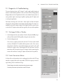
1
D I G I TA L P I C O V I E W
N A N O S P R AY S O U R C E
DPV-550
S of t ware M A N U A L
MODEL DPV-550
PV ACQUIRE 550 1.6x
PV CONFIGURE 150/550 1.1
2 Constitution Way
Woburn, Ma 01801-1023 USA
800 220 2998 US toll free
781 933 9560 phone
781 933 9564 fax
www.newobjective.com
D I G I TA L P I C O V I E W
N A N O S P R AY S O U R C E
S of t ware M A N U A L
FOR MODEL DPV-550
PV ACQUIRE 550 1.6x
PV CONFIGURE 150/550 1.1
© 2009 New Objective, Inc.
All rights reserved.
No portion of this document
may be repurposed or reprinted
without the prior written consent
of New Objective, Inc.
Ta b le o f C ontents
Table of Contents
1
Introduction
1-1
Software Overview
1-1
Prior to Installation
1-1
2
Read this First
2-1
Document Conventions
2-1
Safety Considerations
2-2
Prior to Installation
2-2
Handling Fused-Silica Tubing
2-2
Tip Adjustment and/or
Replacement
2-2
The Transfer Line
2-2
Trademarks
2-3
Limited Warranty
2-3
Version
2-3
3
System Components
3-1
Host PC System Requirement
3-1
Compatible Operating Systems
3-1
Software Checklist
3-1
Hardware Checklist
3-1
D igital P icoV iew S O F T WA R E m anual
i
D igital P icoV iew S O F T WA R E m anual
Ta b le o f C ontents
ii
4
Software Installation
4-1
PV Acquire Software Installation
4-1
5
Software & Hardware Initialization
5-1
Connecting USB cables
5-1
USB Port Setting Determination
5-1
Choosing an Alternate COM Port
5-1
6
PV Configure Application
6-1
Overview
6-1
Creating a Configuration Settings File
6-2
7
PV Acquire 550 Application
7-1
PV Acquire Start-up
7-1
Overview
7-2
The Settings Tab
7-4
The Mode Tab
7-5
Image Settings
7-6
Setting Image Exposure Time (µS)
7-6
Setting Image Gain (dB)
7-6
Setting Acquisition Loop Time (mS) 7-6
Image Magnification
7-7
Ta b le o f C ontents
Image Tools
7-7
Image Panning with the Mouse
7-8
Image Zooming with the Mouse
7-8
Panning Scrollbar
7-8
Saving Images
7-9
Using Measurement Cursors
7-11
Stage Control Commands & Parameters
7-11
Tune Tab Commands
7-12
Using Manual XYZ Stage Control Knobs
7-12
Using Automated Stage Polling
7-14
Setting Retract Position
7-14
Setting Home Position
7-15
Quitting PV Acquire
7-16
Restarting PV Acquire
7-17
8
Advanced Features
8-1
Go To Page Direct Coordinate Movement
8-1
Store Page Commands
8-1
Digital Divert™
8-2
Configuration Choices
8-2
Activating Digital Divert
8-3
Testing Digital Divert
8-3
Digital Divert Control Buffer
8-4
D igital P icoV iew S O F T WA R E m anual
iii
Ta b le o f C ontents
9
Emitter Positioning Procedures
9-1
Positioning a New Emitter
9-1
D igital P icoV iew S O F T WA R E m anual
9-2
Gross Automated Emitter
Positioning Using the
Stage Control Panel
9-2
Fine Automated Emitter
Positioning Using the
Stage Control Panel
9-3
iv
Automated Emitter Positioning Using Stage Control Commands
and Parameters
Emitter Positioning Using a Combination of Manual and
Automated Stage Controls
9-4
Emitter Positioning Using 9-4
Manual Knob Controls
Automated Fine Emitter
Positioning Using the
Stage Control Panel
Setting the Crash Limit
9-6
Parking an Emitter
9-6
Setting an Emitter Rinse Position
9-7
Getting a New Emitter to a Previous Spray Position
9-8
9-5
Ta b le o f C ontents
10
Diagnostics/Troubleshooting 10-1
No Image Visibile in Video Window
10-1
Serial Connection Failure
10-1
Incorrect COM Port Assignment
10-2
PV Acquire User Interface Frozen
10-2
D igital P icoV iew S O F T WA R E m anual
v
D igital P icoV iew S O F T WA R E m anual
Ta b le o f C ontents
vi
1
:
I ntroduction
1. Introduction
Welcome to the Digital PicoView® Software Instruction Manual. This manual
describes the installation and operation of the PV Acquire Software module to
be used with Digital PicoView hardware from New Objective Inc. In addition to
being a useful reference, this manual can be utilized during user training. Storing
this manual near the computer operating your Digital PicoView is highly recommended.
1.1 S o f t w a r e O v e r v i e w
The Digital PicoView® software package consists of two main modules. The first
is PV Configure which is used to set up and configure a default settings file. The
second is PV Acquire which is the application that provides the graphical user
interface for the source. PV Acquire enables remote stage positioning, high resolution spray imaging, and advanced features such as Digital Divert™.
This manual guides you through the installation of PV Configure and PV Acquire
software and the source-software communication hardware. The sections guide
you through the daily procedures of software initialization, image optimization,
and tip positioning.
Your separate Digital PicoView Hardware Manual is your reference for source
assembly, hardware configuration and specific nanoelectrospray applications.
Additional resources for nanoelectrospray applications can be found in the Tech
& App Notes section of the New Objective website:
D igital P icoV iew S O F T WA R E m anual
http://www.newobjective.com/resources/app_notes.html.
1-1
D igital P icoV iew S O F T WA R E m anual
1
1-2
:
I ntroduction
2
2. :
R ead T his First
Re a d T his First
Software from the Digital PicoView® Installation CD should be installed
and the host PC rebooted prior to making the USB connections between
the Digital PicoView Camera, XYZ actuators, and host PC.
2.1 D o c u m e n t C o nv e n t i o ns
This manual employs several conventions to describe mouse operations, software functions, and alert the user with important information. For your reference, these document conventions are delineated below.
Helpful Tips & Precautions
This manual contains notes to the user for working with Digital PicoView.
Helpful tips provide shortcuts or guidelines for best practice.
Indicates a warning or essential step to avoid future error or complication.
Indicates potential for injury by electric shock.
Indicates an extremely hot surface
Indicates an operation requiring eye safety protection
Indicates an operation requiring protective gloves
Indicates an operation using fragile material(s)
D igital P icoV iew S O F T WA R E m anual
2.2 S a f e t y C o nsi d e r a t i o ns
Electrospray ionization (ESI) involves the use of potentially lethal highvoltage electrical current. Observe all manufacturers’ safety recommendations in the use of such equipment. No equipment modifications should be
made except by trained personnel using methods approved by the manufacturer in accordance with all safety requirements. Installation of equipment should be performed by qualified personnel in accordance with all
applicable electrical codes.
2-1
2
:
R ead T his First
Never use this product with defective, damaged, or faulty equipment. Serious injury or death could result.
Only qualified personnel should use this product. Provide a safe workplace
equipped with all necessary safety equipment.
2.2.1 Prior to Installation
Follow all safety recommendations of the equipment manufacturer(s). All system voltages must be brought to ground potential and all high-voltage contacts
disconnected from the inlet system before installation of the Digital PicoView
system.
Inspect all equipment carefully prior to use. Any damaged, chipped, or cracked
components should not be used and must be discarded or repaired.
2.2.2 Handling Fused-Silica Tubing
Handling of fused-silica or glass tubing and tips can result in serious personal injury. Use safety glasses or goggles meeting ANSI Z87.1-1989 requirements, or the equivalent. Puncture-and chemical-resistant gloves
should also be worn at all times.
2.2.3 Tip Adjustment and/or Replacement
Do not attempt to adjust or replace the tip unless the ESI high voltage and other
applicable voltages are turned off and are at ground potential.
D igital P icoV iew S O F T WA R E m anual
Reduce any applicable backing pressure (liquid, gas, etc.) to ambient before loosening ESI tip fittings and removing the fused-silica tip or transfer
line from the coupling union. Prior to pressurization, make sure that components are tightened to specifications to prevent separation during use.
Failure to adhere to this warning could result in projectile-like expulsion of
the tip from the coupling union, which could cause serious personal injury
or damage to surrounding apparatus.
2.2.4 The Transfer Line
The transfer line connecting to either a tip module or the Micro Injection Valve
must not be made from an electrically conductive material. It must be fabricated
from an electrically insulating material such as PEEK™ or fused silica. Otherwise,
the operator may be exposed to potentially lethal voltage.
2-2
2
:
R ead T his First
In systems where high voltage is applied directly to the ESI tip, the liquid sample
inside the tip and transfer line tubing is also raised to a high voltage. To prevent
exposure to potentially lethal voltages, a suitable ground point for the liquid
inside the line must be provided.
Do not operate Digital PicoView without the external housing and lid in
place.
Do not defeat any mass spectrometer system software or hardware safety
interlocks.
2.3 Tr a d e m a r k s
The following trademarks are found in this instruction manual.
Teflon is a registered trademark of E.I. du Pont de Nemours and Co.; MicroTight
and SealTight are trademarks or registered trademarks of UpChurch Scientific
Inc., a division of IDEX; PEEK and PEEKsil are trademarks of Victrex plc; LabVIEW
is a trademark of national Instruments. Windows, Windows 2000, Windows
NT, Windows XP, Windows Vista, Paint, and PowerPoint are trademarks or
registered trademarks of Microsoft Corporation. PicoView, Digital PicoView,
PicoTip, PicoFrit, IntegraFrit, SilicaTip, TaperTip, GlassTip, PicoClear, and PicoTip
Powered are trademarks or registered trademarks of New Objective, Inc. All
other trademarks are the property of their respective companies.
2.4 L imit e d Wa r r a n t y
D igital P icoV iew S O F T WA R E m anual
This software under draft release bears no warranty whether implied or otherwise.
2.5 Ve r si o n
This manual was written to be current with PV Configure version 1.1 and PV
Acquire version 1.6x.
2-3
D igital P icoV iew S O F T WA R E m anual
2
2-4
:
R ead T his First
3
:
S yste m C o m ponents
3. Syst e m C o m p o n e nt s
3.1 Host PC System Requirements
3.1.1 PV Acquire is compatible with the following operating systems:
- Windows® Vista™
- Window® XP™
- Windows® NT™
- Windows® 2000™
Optimal performance has been found on Windows® XP. A standard CD-ROM
drive is required for software installation.
The host PC is required to support two USB 2.0 (or better) connections.
3.2 S o f t w a r e Ch e c k lis t
- Digital PicoView® Software Installation CD.
All of the required application software, device drivers, dll’s, and the National
Instruments Run-Time Engine are on this single CD.
- Digital PicoView Operator’s Manuals CD
3.3 Hardware Checklist
D igital P icoV iew S O F T WA R E m anual
- Digital PicoView® Nanospray Source with actuators & camera installed
(See Digital PicoView Hardware Manual for configuration)
- USB-to-Serial Port Converter
- Serial Cable for Connecting Actuators to Converter
- USB Cable for Camera to Computer connection
- PCI USB 2.0 Card for PC
3-1
D igital P icoV iew S O F T WA R E m anual
3
3-2
:
S yste m C o m ponents
4
:
S o f tware I nstallation
4. S o f t wa re I nst a ll a t io n
Software from the Digital PicoView® Installation CD should be installed
and the host PC rebooted prior to making the USB connections between
the Digital PicoView® Camera, XYZ actuators, and host PC.
4.1 P V A c q uir e S o f t w a r e I ns t a l l a t i o n
Confirm installation
1. Locate the Digital PicoView® Software Installation CD
2. Insert the CD into the host PC CD-ROM drive. The CD contains an autorun
application (cdstarter.exe) that will start-up with the dialog box at right.
3. Accept the dialog box by clicking YES. The start-up window appears
4. Click on 1-USB to Serial Install to install the USB-to-serial converter driver.
Follow the default installation instructions.
5. Click 2-Camera Install to install the camera drivers. Follow the default installation instructions.
Startup dialog box
6. Click 3-PV Configure Install to install the PV Configure application. Follow the
default installation instructions.
7. Click 4-PV Acquire Install to install the PV Acquire application and National
Instruments™ Run-Time Engine. Follow the default installation instructions.
8. Restart/re-boot the host PC.
The host PC must be rebooted to complete software installation. Do not
connect the USB cables from Digital PicoView® Hardware prior to rebooting, as this will casue software failure.
Two Digital PicoView applications will be
added under the Windows START menu
10.A successful installation will also result in two icons being added to the desktop. These icons point to applications for digital camera diagnostic software.
These pointers may be deleted from the desktop at no risk.
11. Additional Installation Notes are available on the CD-ROM, follow these
directions should the cdstarter.exe application fail to run.
Two additional icons will be added to the
desktop upon installation. These are not
required and may be deleted without risk.
4-1
D igital P icoV iew S O F T WA R E m anual
9. Two Digital PicoView applications have been installed in the Windows®
START menu: Digital PicoView > PV550 Acquire1_6 and PV Configure.
D igital P icoV iew S O F T WA R E m anual
4
4-2
:
S o f tware I nstallation
5
:
S o f tware & H ardware I nitiali z ation
5. S o f t wa re a n d H a rd wa re I nit ia liz a t io n
5.1 C o n n e c t t h e U S B c a b l e s
Prior to using PV Acquire, the USB connections between the host PC and Digital
PicoView® source need to be established. This will be followed by the creation
of a default configuration file using the PV Configure application.
1. Connect the USB cable from the digital camera to the host PC. Follow instructions to activate USB driver (if required). (Figure 5.1)
2. Connect the USB cable from the USB-to-serial converter to the host PC.
Follow instructions to activate USB driver (if required). (Figure 5.2)
Figure 5.1
5.2 S e t t in g a Po r t A s si g n m e n t f o r U S B-t o -S e r i a l A d a p t e r
The USB-to-serial adapter will be assigned a virtual COM port number by the
operating system. This number needs to be determined and is used by the PV
Configure application to establish a default settings file for PV Acquire.
1. Open the Windows Device Manager. In Windows XP this is typically found
under: Start > Control Panel (classic view) > System > Hardware Tab (See
Figure 5.3)
Figure 5.2
2. Click on the Device Manager button
3. The Device Manager List will open. Click on Ports (COM & LPT). Look for
Prolific USB-to-Serial Comm Port in the sub-list (See Figure 5.4).
D igital P icoV iew S O F T WA R E m anual
4. Note the COM port setting (e.g. COM3, COM4, etc.) that will be seen in
parenthesis (this assignment will be needed when running PV Configure for
the first time).
5.3 S e l e c t in g a n A l t e r n a t e CO M Po r t ( o p t i o n a l )
If the COM port setting chosen by the operating system is in conflict with another device, the COM number may be assigned manually. This may resolve
serial port conflicts.
1. Right-click on the Prolific USB-to-Serial Comm Port device in the Device
Manager list and select Properties from the pop-up menu (Figure 5.5).
Figure 5.3
2. Click on the Port Settings tab.
5-1
5
:
S o f tware & H ardware I nitiali z ation
3. Click on the Advanced... button.
4. Choose an alternate COM Port Number from the menu list (Figure 5.6).
5. Click the OK button in the Advanced Settings window.
6. Click the OK button in the Properties window.
Figure 5.4
D igital P icoV iew S O F T WA R E m anual
Figure 5.5
Figure 5.6
5-2
6
6. :
P V C on f igure A pplication
P V C o nf ig u re A p p lic a t io n
PV Configure must be run once prior to the first activation of PV Acquire.
The settings file created by PV Configure is required for the operation of
PV Acquire.
6.1 P V C o nf i g u r e O v e r v i e w
PV Configure generates a default settings configuration file (*.ini file) that PV
Acquire is required to open each time it runs. Think of this much like a “tune
file” for your digital source settings. The default settings configuration file saves
the following information:
COM port assignment
- Number of the COM port for communication with the XYZ Stage
through the USB-to-serial adapter
XYZ Stage Poll Stage Position On/Off and Timing
- Controls if PV Acquire should periodically Poll the XYZ stage for
changes in manual (Knob Control) position
- Standard Value is OFF.
XYZ Stage Knob Control On/Off
- Turns the manual adjustment knobs on each XYZ controller On/Off
- Standard Value is OFF
XYZ Stage Direct Goto Position
•
- Sets the default XYZ Stage position for the retract position.
XYZ Stage Retract Position
•
- Sets the default XYZ Stage position for the direct go-to command
- Used as the retract position for Digital Divert™
Camera Exposure and Gain Settings
•
- Sets start up values for image brightness and Gain
Camera Acquisition Loop Time
•
- Sets the acquisition period (in milliseconds) for image acquisition
- Settings below the default value (102 mS) may result in a slow down D igital P icoV iew S O F T WA R E m anual
6-1
6
:
P V C on f igure A pplication
of the user interface. The default value yields a frame rate of
approximately 8-10 images/sec.
• Cursor Calibration (Cal X, Cal Y ) Values
Figure 6.1
- Sets the mm calibration value (in µm/pixel) of the on-screen cursors
- Value should ONLY be changed from default settings if the optical tube or
lens is changed from standard configuration.
- Cal X and Cal Y default values are 10.7 µm/pixel
• Multiple PV Configure settings files may be used. Each user can have one or
more settings files to accommodate different nanospray configurations.
• All of the settings, with the exception of the COM port value, may be changed
directly from within PV Acquire.
6.2 Cr e a t in g A C o nf i g u r a t i o n S e t t in g s Fil e
1. Select PV Configure from the Windows START menu under the Digital
PicoView® heading. A dialog box asking you to select the proper COM port
will pop up. (Figure 6.1)
2. Select the COM port number from the menu selection as reported by the
Device Manager in section 4.2. In this example the selected COM port is
COM3.
3. The main PV Configure dialog window is now available:
4. Select and modify each of the desired configuration parameters.
D igital P icoV iew S O F T WA R E m anual
Guidelines for typical set-up:
- Direct Goto & Retract: default values are good starting points.
- Camera Settings:
- Exposure = 20,000 µS
- Gain = 10 dB
- Acquisition Loop Time = 102 mS
- Poll Stage Position Every: OFF
- Knob Control: ON is useful for “manual” source tuning
- Cal X, Cal Y: Default Values of 10.7 for each
5. Click Save to save the settings file. A standard dialog window will open. The
file may be saved under any name, to any user-selected directory.
6-2
6
:
P V C on f igure A pplication
6. Note the file location and file name. Click the OK button to save the file. The
PV Configure window will close automatically.
COM Port
Assignment
XYZ Stage
Position(s)
Camera
Settings
Screen Cursor
Calibration
Save Settings
to File
D igital P icoV iew S O F T WA R E m anual
Stage Polling
XYZ Stage
Knob Control
On/Off
Figure 6.2
6-3
D igital P icoV iew S O F T WA R E m anual
6
6-4
:
P V C on f igure A pplication
7
:
P V A C q uire A pplication
7. P V Ac q uire 55 0 A p p lic a t io n
7.1 P V A c q uir e S t a r t -u p
PV Acquire requires user input of the location of the Configuration File each
time it is started. The XYZ stage also requires a Home Stage operation if it is the
first use of the stage or if the power to the stage motors has been interrupted or
disconnected. The Home Stage operation sets the (0,0,0) point for XYZ stage
motion. Operation without establishing the proper Home position will result in
erratic stage positioning and a loss of range of motion.
Figure 7.1
1. Choose PV Acquire from the Start menu under the Digital PicoView®
heading.
2. A dialog window asking for the location and name of the Configuration File
created in section 6.2 will appear. Choose the File and click OK (Figure 7.1)
3. A second dialog window will open asking if the XYZ stage requires a Home
Stage operation. The Home Stage operation is required if this is the first use
of the stage or if power to the stage motors has been interrupted or disconnected (Figure 7.2)
A Home Stage operation must be performed when the Digital PicoView®
stage is used for the first time OR if power to the unit’s XYZ stage has been
disrupted or disconnected.
When the Home Stage operation is finished a dialog window will appear
notifying the end user.
Figure 7.2
D igital P icoV iew S O F T WA R E m anual
4. Once the stage is fully initialized and PV Acquire has established communication with the XYZ stage motors, a confirmation dialog window will appear
(Figure 7.3). This message only appears at statup, however, not each time the
stage is “homed”.
5. Click OK in the message box to begin using PV Acquire.
Figure 7.3
7-1
7
:
P V A C q uire A pplication
7.2 O v e r v i e w
PV Acquire™ is a powerful user interface for Digital PicoView® enabling a high
level of productivity for nanospray enabled mass spectrometry. The user interface supplies an interactive digital image of the MS inlet and the necessary
controls for XYZ stage positioning. Advanced features such as Digital Divert™
enable the remote control of emitter XYZ position from other instruments such
as autosamplers, or liquid chromatographs.
D igital P icoV iew S O F T WA R E m anual
One of the most useful features of the Digital PicoView platform is the smart XYZ
motor controls used for stage actuation. Each controller is an independent microprocessor driven device. The Digital PicoView platform can be used without
the PV Acquire application. It also ensures that the stage position and spray performance will not be effected if PV Acquire is exited unexpectedly. PV Acquire
can be readily re-started without effecting the stage position. See Section 7 for
use of the manual stage controls.
7-2
I n t e r f a c e Fe a t u r e
Pe r f o r m a n c e
Section
Main Window
Choose Settings, Source
Image, or Diagnostics
7.1.1
Measurement
Cursor
User drag-and-drop placement
for distance measurement and establishing reference positions
Cursor Readout
Shows X, Y distance (mm) between cursor centers
Image Controls
Real Time Camera Exposure,
Gain, Image Magnification,
and Image Panning controls
7.3, 7.4, 7.5
Stage Control Panel
Buttons enable precise XYZ
jogging of stage
7.6
Digital Divert™ Panel
Remote (contact closure or digital
input) switching between spray
and retract/rinse position
Mode Panel
Choose Tune, Store, Go To, or Retract &
Home Tabs for In-depth control features
7.1.2
7
Main Window
Settings,
Source Image,
Dignostics,
tabs
:
P V A C q uire A pplication
Stage
Control
Panel
Measurement
Cursors
Blue - Inlet
Green - Emitter
Digital
Divert™
Panel
Mode Panel
Tune,
Store,
Cursor
Readout
Image
Controls
Go To,
Retract & Home
tabs
D igital P icoV iew S O F T WA R E m anual
Figure 7.1 Primary PV Acquire™ window
7-3
7
:
P V A C q uire A pplication
7.2.1 Settings Tabs
The Settings tabs, found at the top of the main window, offer three levels of control: Settings, Source Image, and Diagnostics (Figure 7.2).
D igital P icoV iew S O F T WA R E m anual
Figure 7.2 PV Acquire Settings Tab
7-4
Main Window
Button/Feature
Comment
Source Image Tab
Exposure, Gain, Apply
Controls Camera Exposure
Time and Image Gain
Source Image Tab
Image Magnification
Sets the Digital Image
Magnification Value
Source Image Tab
Image Tool
Selects Cursor, Mouse Pan,
Mouse Zoom modes.
Source Image Tab
Pan X, Pan Y
Sets image shift values
when using Image Mag
Values of 2 or 3X.
Settings Tab
Acquisition Loop Time
Controls refresh rate of
source image from camera,
default value of 102 mS.
Settings Tab
Stage Polling
Controls how often PV Acquire
communicates with Stage
Controllers. Used when lots
of manual (knob) positioning
is used. If the default value is
off, user interface may become sluggish on some PC’s.
Settings Tab
Knob On/OFF
Controls whether the XYZ
Stage Motor controller
knobs are active or inactive
for manual positioning.
Settings Tab
Cal X, Cal Y
Cursor measurement calibration
values, typically these are NOT
changed from default values.
Diagnostics Tab
CCD Camera
Communication and error values with Camera
Diagnostics Tab
Cursor
Displays Raw Cursor information, used for recalibration
of Cal X, Cal Y Values.
Diagnostics Tab
Configuration File Path
File path of the Configuration
Settings File chosen at start-up
Diagnostics Tab
Com Port Assignment
Value of the COM
Port assignment
7
:
P V A C q uire A pplication
7.2.2 Mode Panel – Advanced Feature Controls
Button/Feature
Comment
Tune Tab
Retract Tip
Moves stage from Current
Position to the Retract
Position as defined on the
Retract & Home page
Tune Tab
Restore Tip
Moves stage from
Retract Position to last
used Current Position
Tune Tab
Update Manual Pos
Forces a read and update
of the XYZ Stage position.
Used after a manual
(knob driven) stage move.
EXIT
Preferred way to quit
PV Acquire application. Properly releases
all memory resources
and asks if update to
Settings file is desired.
Store Tab
Save Pos File
Saves a position file
to disk which contains
the current XYZ Stage
and cursor positions
Store Tab
Load Pos File
Loads a previously saved
position file and moves the
XZY Stage and Cursors
to saved positions
Go To Tab
Direct X, Direct
Y, Direct Z
Sets the coordinates for
direct stage control
Go To Tab
Apply
Moves the Stage to
position defined by Direct
X, Direct Y, Direct Z
Retract & Home Tab
Retract X, Retract
Y, Retract Z
Sets the coordinates of
the Retract Position
Retract & Home Tab
Retract Tip
Moves the Stage to
the Retract Position
defined by Retract X,
Retract Y, Retract Z
Retract & Home Tab
Home Stage
Performs Home
Stage Operation
Tune Tab
D igital P icoV iew S O F T WA R E m anual
Mode Panel
7-5
7
:
P V A C q uire A pplication
7.3 I m a g e S e t t in g s: E x p o s u r e, G a in, A c q uisit i o n T im e
The camera acquisition controls enable complete control over image quality
enabling optimal spray, inlet or emitter imaging.
If the Exposure setting is too low, the Source Image will appear black. If the
setting is too high, the image will be washed out (Figure 7.3). Figure 7.4 depicts
adjustments set for optimal camera exposure.
Figure 7.3 Camera exposure setting too
high
7.3.1 Setting Image Exposure Time (µS)
Exposure controls image quality with respect to image illumination, just like the
exposure time of a digital or film camera.
1. Place the mouse over the arrow on the Exposure (µS) scale and drag to the
desired position (15,000 - 20,000 µs works in most cases) (Figure 7.5).
2. Click Apply and note changes in image brightness.
Continue adjustment to attain desired brightness/contrast.
7.3.2 Setting Image Gain (dB)
Gain controls image enhancement, contrast range, and noise level. Increasing
the gain allows for a shorter exposure time (e.g. used to image spray dynamics)
but increases image noise.
D igital P icoV iew S O F T WA R E m anual
Figure 7.4 Camera exposure optimized
1. Click the arrow on the Gain (dB) scale and drag to the desired position (8-10
dB works in most cases) (Figure 7.5).
2. Click Apply and note changes in image quality. Continue adjustment to attain
desired image clarity.
7.3.3 Setting Acquisition Loop Time (mS)
Acquisition Loop Time controls the image refresh rate. A low setting (< 50 mS)
can be used to monitor spray dynamics and is useful to observing transient spray
behavior. Settings below 100 mS can compromise the response time of the PV
Acquire user interface and possibly lead to interface lock-up.
1. Click on the Settings tab in upper left corner of the screen
2. Click the arrow on the Acquisition Loop Time (mS) scale and drag to the desired position (About 100 mS works in most cases).
7-6
7
:
P V A C q uire A pplication
3. Click Apply and note changes in image quality in the Image Preview screen
on the right. Continue adjustment to attain desired image clarity.
Decreasing Acquisition Loop Time increases image frame rate but lowers
performance of the user interface.
Figure 7.5 Camera Acquisition Controls
7.4 I m a g e M a g nif ic a t i o n
Magnifying the Source Image to 1X, 2X, and 3X provides digital magnification of
fine image details. Radio buttons located in the lower right corner of the Source
Image screen allow rapid transition from one magnification level to another; 1X
is the default magnification level.
Figure 7.6 Image Tools drop-down menu
To change magnification level, click the corresponding radio button and wait for
the image to refresh (Figures 7.6).
7.5 I m a g e To o ls
Image Tools define available mouse modes when the mouse is placed over the
image display. Availability of Image Tools depends on magnification level.
At 1X magnification, Select Cursor is the only active Image Tool. Select Cursor
transforms the mouse into a crosshair cursor (+), allowing the user to move the
green reference cursor in the Source Image display screen.
Additional tools activate upon selecting 2X or 3X magnifications. These tools are
grayed-out at 1X magnification.
D igital P icoV iew S O F T WA R E m anual
1. Select a higher magnification level.
2. Click the dropdown menu immediately below Image Tools and select desired
tool (Figure 7.6).
7-7
7
:
P V A C q uire A pplication
7.5.1 Image Panning with the Mouse
Pan converts the crosshair cursor to a hand to allow manual image panning.
Mouse panning position is reset each time the magnification is changed.
1. Select Pan in the Image Tools dropdown.
2. Place the hand cursor over image display.
3. Click and drag to “pull” desired image components into view.
7.5.2 Image Zooming with the Mouse
Zoom In and Zoom Out functions allow image display expansion and contraction.
1. Select Zoom In from the Image Tool dropdown.
2. Click in the image display.
3. To return to the initial magnification, click Zoom Out from the Image Tools
dropdown.
Figure 7.7 Pan X and Pan Y scrollbars
7.5.3 Panning Scrollbar
The Pan X and Pan Y scrollbars in the lower left corner of the Source Image
tab provide horizontal and vertical scrolling, respectively. Panning enables you
to move the observable image space at 2X and 3X magnifications. Unlike the
mouse panning option, Pan X and Pan Y scrollbar settings are saved when image
magnification settings are changed.
1. Select either 2X or 3X from Image Magnification.
D igital P icoV iew S O F T WA R E m anual
2. Click the arrow on the Pan X or Pan Y slot and drag to the desired position
see Figure 7.7).
The Pan, Zoom In, and Zoom Out options from the Image Tools dropdown
and the Pan X and Pan Y scrollbars are only active at the 2X and 3X image
magnifications.
7-8
7
:
P V A C q uire A pplication
7.6 S a v in g I m a g e s
The Source Image is readily captured with a copy-and-paste operation into another application such as Windows® Paint. The background image and cursors
will be saved, the cursor distance readout, however, is not.
1. Right clicking in the image window will bring up a pop-up menu.
2. Select Copy Data (Figure 7.8).
3. Use a paste operation in another suitable application such as Paint or
Microsoft ® Powerpoint ®.
Figure 7.8 Use the Copy Data feature to
copy images to the clip board for use in
other applications
D igital P icoV iew S O F T WA R E m anual
7-9
7
:
P V A C q uire A pplication
Source Cursor
(blue)
Y Axis
X Axis
Emitter Cursor
(green)
D igital P icoV iew S O F T WA R E m anual
Cursor
Readout
Figure 7.9 Measurement cursors provide precise reporting on distance between the two
cursor positions
7-10
7
:
P V A C q uire A pplication
7.7 Usin g M e a s u r e m e n t Cu r s o r s
There are two measurement cursors:
Blue Cursor – inlet cursor
Green Cursor – emitter cursor
Cursors are placed with a drag-and-drop mouse operation using the left mouse
button.They are a powerful tool for establishing long-term, repeatable emitter
positioning
Typically the blue cursor is placed at the position of the mass spec inlet, and the
green cursor is placed at the emitter position. The Cursor Readout will then show
the precise distance between the inlet and emitter.
Figure 7.10 Stage Control panel
To position a cursor:
1. Position the mouse cursor over either screen cursor. The mouse cursor will
change shape from a solid to hollow cross. (Note the blue cursor is a center
marked line, and should be grabbed at the center mark.)
2. Left click-and-hold the mouse while dragging the screen cursor to the desired position.
3. Release the mouse button.
The Cursor Readout will show an updated distance measurement between the
two cursors. (Figure 7.9)
7.8 S t a g e C o n t r o l C o m m a n d s & Pa r a m e t e r s
D igital P icoV iew S O F T WA R E m anual
You can easily control XYZ position of the emitter tip using the Stage Control
commands in the upper right corner of your screen.
The Stage Control contains two fields and six positioning commands (Figure 7.10).
Crash Limit defines the maximum forward tip Y distance (µm) before colliding
with the mass spec inlet. While the default limit is 12,500 µm, you can customize
the value for each emitter.
Step Size is the incremental distance (µm) traveled by the tip when you press any
of the Stage Control buttons.
7-11
7
:
P V A C q uire A pplication
The L and R arrows (Left/Right) move the tip along the source X-axis by an increment defined by the selected Step Size.
The In and Out arrows move the tip along the source Y-axis by an increment
defined by the Step Size.
The Up and Down buttons move the tip along the source Z-axis by an increment
defined by the Step Size.
Stage Position reports the current stage position.
Stage Retracted LED turns on (green) when the stage is in the Retract Positon.
7.9 Tu n e Ta b C o m m a n d s
Tune tab of the Mode panel contains basic emitter-actuator positioning functions
and allows you to properly exit PV Acquire™ .
Click the Tune tab in the Mode panel (Figure 7.11)
Click Retract Tip to move the emitter to the Retract, X, Retract Y, Retract Z coordinates, as set on the Retract & Home tab of the Mode panel.
Figure 7.11 Tune tab in the Mode panel
Click Restore Tip to move the emitter to the last established position before the
retract button was pressed
Click Update Manual Pos to establish communication between PV Acquire and
the XYZ stage motor controllers to determination the current stage position.
D igital P icoV iew S O F T WA R E m anual
Click EXIT every time to quit PV Acquire.
Always click on the EXIT buttion when closing PV Acquire. Closing the
software using other methods may leave memory resources unavailable to
other applications.
7.10 Usin g M a n u a l X Y Z S t a g e K n o b C o n t r o ls
The manual XYZ stage knob controls are an effective way to drive the emitter
tip to the desired spray position. They also enable stage movement when PV
Acquire is not running.
7-12
7
:
P V A C q uire A pplication
1. Click on the Settings tab.
2. Click on the Knob Controls switch to turn it on (blue=on; gray=off), and click
Apply (Figure 7.12).
3. Each knob control of the X, Y, or Z actuator can be turned clockwise or
counter-clockwise from a central, detent position to move the stage. The
speed of movement is proportional to the degree of turning away from the
detent position. Clockwise rotation extends the motor actuator; counterclockwise rotation retracts the motor actuator. During movement the moving
actuator yellow LED will turn on.
4. Once the stage is in the desired position, adjust the knob controls to the
central, detent position. The detent position can be verified by making sure
the yellow LED on each actuator motor is off. (Green indicates power is ON
and is normal.)
5. Go to the Tune tab of the Mode panel and click the Update Manual Pos button.
This ensures that PV Acquire is aware of the newly established stage position.
Always click Update Manual Pos whenever you manually adjust any of the
XYZ actuators. Failure to do so will result in unpredictable stage movements.
It is critical that each knob control is in the central, detent position after
making a manual stage move. If the knob control is left slightly off center,
the stage will continue to slowly move and may result in a tip crash.
D igital P icoV iew S O F T WA R E m anual
7-13
7
:
P V A C q uire A pplication
7.11 Usin g Au t o m a t e d S t a g e Po l lin g
Figure 7.12 Manual stage knob control
panel
Use of the manual XYZ stage knob controls requires the user to click on the
Update Manual Pos so that PV Acquire™ knows the resulting stage position. If the
user strongly prefers to use knob controls, rather than user stage control commands for the XYZ stage, forgetting to perform Update Manual Pos is problematic.
Mixing the knob controls and stage control could result in unpredictable stage
movement when the arrow buttons are pressed. To circumvent this situation, PV
Acquire can periodically poll the XYZ stage for its current position automatically.
1. Click on the Settings tab.
2. Click and hold the Poll Stage Position Every (s) drop-down menu.
3. Select a polling interval time of 5, 10 or 30 seconds (recommended).
Figure 7.13 Retract & Home panel
4. Click Apply. You may verify automated polling operation by manually adjusting the stage position using one or more knob control(s) and waiting for the
Stage Position window to update.
Using a short stage polling time (5 or 10 seconds) can result in poor performance of the PV Acquire user interface on certain host PC’s since portions
of the interface are unavailable during the update position operation.
7.12 S e t t in g Re t r a c t Po sit i o n
D igital P icoV iew S O F T WA R E m anual
The Retract Position is typically used in two different operations: (1) Moving the
emitter far from the MS inlet making it easier to change emitters or clean the inlet
etc. (2) Establishing the emitter position for use with the Digital PicoView rinsing
station. The XYZ stage is retracted through the Retract Tip button from the Tune
or Retract & Home tab of the Mode panel. The actual XYZ stage position of the
Retract Position is set on the Retract & Home panel (Figure 7.13).
1. Click on the Retract & Home tab of the Mode panel.
2. Click the Retract Tip button. The stage will move to the settings set by Retract
X, Retract Y, and Retract Z values.The Stage Retracted LED will light up.
3. Note the position of the XYZ stage. If a different Retract Position is desired,
type the new value(s) into Retract X, Retract Y, and/or Retract Z.
4. Click on Retract Tip to move to the new Retract Position.
5. Repeat steps 3-4 until the final desired position is obtained.
7-14
7
:
P V A C q uire A pplication
6. Go to the Tune tab of the Mode panel and click Restore Tip to return XYZ
stage to the operating position.
7.13 S e t t in g H o m e Po sit i o n
The Home Position is defined at the (0, 0, 0) setting of the XYZ stage. The Home
Position is an absolute reference position that both PV Acquire and the motor actuators use in making XYZ stage movements. A Home Position operation must be
performed when the Digital PicoView source is used for the first time. A Home
Position operation must also be performed if the electrical power to the motor
actuators has been disrupted or disconnected.
If you are merely re-starting PV Acquire and the power to the Digital PicoView
source has remained intact, a Home Position operation should not be required.
Figure 7.14 Stage Position settings
1. Click on the Retract & Home tab of the Mode panel.
2. Click the Home Stage button. The stage controls will gray out during the
homing operation.
3. When the homing operation is finished the Stage Position will read (0, 0, 0)
and a dialog window will appear confirming that the stage has been homed
(Figure 7.15).
The current operating position of the XYZ stage will be lost when the
home position operation is performed.
Figure 7.15 Dialog window confirming
that the stage has been reset to the home
position
D igital P icoV iew S O F T WA R E m anual
7-15
7
:
P V A C q uire A pplication
7.14 Q uit t in g P V A c q uir e
The proper way to quit PV Acquire is to always click Exit from the Tune tab of the
Mode panel when closing PV Acquire. Closing the software using other methods
may leave background processes running and memory resources unavailable to
other applications. While other methods such as directly closing the program
window through the Microsoft Windows buttons or using the application stop
button will work to terminate the program, it is not a best practice with PV
Acquire. Using the Exit button ensures that all PV Acquire functions are termintated properly and that saved settings will be retained.
Figure 7.17 When restarting PV Acquire,
the prompt to home the stage can be
declined if power to Digital PicoView has
remained on.
1. Click on the Tune tab in the Mode panel
2. Click on Exit. A dialog box will appear asking if you want to update the default settings file with the currently selected values.
3. Select Yes if you wish to: 1) modify the existing settings file or 2) create a
new settings file with the most recently used Digital PicoView operating parameters. If you answer yes, you will be prompted with a standard file dialog
window.
4. The only other way to exit the program is through the Windows Task Manager
Control Panel (CTL-ALT-DEL), but this method is not recommended.
D igital P icoV iew S O F T WA R E m anual
Always click EXIT before closing the PV Acquire window. Closing the software using other methods may leave memory resources unavailable to
other applications.
7-16
7
:
P V A C q uire A pplication
7.15 Re -S t a r t in g P V A c q uir e
PV Acquire can be re-started with the procedure in section 7.1. However, as long
as the power to the Digital PicoView XYZ stage has remained intact from the last
use, there is no need to execute a Home Stage operation.
The user may safely decline the Home Stage request on re-start (see Figure 7.17).
This way the stage position, spray operation, etc. of the source will not be disturbed during the PV Acquire re-start sequence.
PV Acquire may be exited and re-started without disturbing the physical
operation (stage position, spray voltage etc.) of the Digital PicoView source
provided that a Home Stage operation is NOT performed on re-start.
D igital P icoV iew S O F T WA R E m anual
7-17
D igital P icoV iew S O F T WA R E m anual
7
:
7-18
P V A C q uire A pplication
8
:
A dvanced Features
8. Ad va n c e d Fe a t u re s
8.1 G o To D ir e c t C o o r d in a t e M o v e m e n t
The Go To tab contains a dialog box to enter specific X, Y, Z coordinates for the
emitter and move the emitter to this position. This function should be used with
caution, since once a stage movement is initiated, it cannot be stopped until
executed.
1. Click on the Store tab.
2. Enter Direct X, Direct Y, and Direct Z coordinates specifying the position to
which you wish to move the XYZ stage.
3. Click on Apply to move the stage to the position you specify.
Direct X, Direct Y, and Direct Z go to coordinates on the Go To page is a
good place to “store” the last known optimal spray position for a given
emitter.
8.2 S t o r e C o m m a n d s
Store tab in the Mode panel contains functions for storing and re-loading stage
and cursor position files you select. The position and cursor information is stored
as a date and time stamped text file. The name of the file may be changed to a
title selected by the user.
1. Click on the Go To tab
Figure 8.1
D igital P icoV iew S O F T WA R E m anual
2. Click Save Position to save the current emitter position and cursor setting in
a position file.
3. Click Load Position to load a position file that will restore the cursor and stage
to the position contained in that position file.
Once the file is loaded, the cursors will move to the saved position and the stage
will move to the new coordinates.
8-1
8
:
A dvanced Features
8.3 D i g it a l D i v e r t™
Figure 8.2 Toggle Digital Divert ON
Figure 8.3 Digital Divert configuration
Digital Divert™ is a powerful feature that enables control of the Digital PicoView
source from a third party hardware platform. Control is via low level interface,
either a traditional contact closure or digital (TTL compatible) control signal. The
interface enables remote toggling of the XYZ stage position between the operating and retract positions.
Another instrument (mass spectrometer, autosampler, liquid chromatograph,
etc.) can then be used to control whether the nanospray emitter is in the operating (spray) position or the retracted (rinse) position. The combined system
ensures that both the mass spec inlet and emitter stay as clean as possible during
repetitive LC-MS/MS runs. For example, some LC’s provide a so-called “Run out”
signal that is actively true when a gradient is being delivered. This can be used
to enable Digital PicoView to position the emitter in the spray position during
gradient elution and in the rinse position for loading, column conditioning, etc.
The Digital Divert interface is made available through the Digital PicoView
source camera. A cable and interface box connected to the camera provides
the connection point for the interface. Refer to the Digital PicoView Hardware
Manual for instructions on making the physical interface connections and setting
up the emitter rinsing station.
PIN 1 - CONTACT CLOSURE (+5V) CH 0
PIN 2 - CONTACT CLOSURE (IN–) CH 0
PIN 3 - DIGITAL IN (+) CH 1
PIN 4 - DIGITAL IN (–) CH 1
+5V plug
DIGITAL IN (-) CHANNEL 1
DIGITAL IN (+) CHANNEL 1
CONTACT CLOSURE (IN–) CHANNEL 0
D igital P icoV iew S O F T WA R E m anual
CONTACT CLOSURE (+5V) CHANNEL 0
8.3.1 Configuration Choices
The Digital Divert™ interface gives a choice over the type of control (contact
closure or TTL compatible) and the polarity of the interface. The type of control
is determined by the selected control channel.
Channel Selection:
Figure 8.4 Digital Divert Interface Box
8-2
Channel 0 is for conventional contact closure and requires an actual contact
between pins 1 and 2 of the Interface Box (Figure 8.8). The input is true
when the contact is closed. The Channel 0 LED will light when the contact
is closed.
Channel 1 is for a TTL level compatible digital signal. The input is true when
the voltage between pins 3 and 4 of the interface box is approx. 2.3-2.8 V or
greater (5 V max.). The Channel 1 LED will light when the voltage is high.
8
:
A dvanced Features
Divert when input is:
True will divert the XYZ stage to the retract position when the channel is true.
When the channel is false the XYZ stage will be in the spray position.
False will divert the XYZ stage to the retract position when the channel is
false. When the channel is true the XYZ stage will be in the spray position.
The desired operating (spray) and retract (rinse) positions should be fine
tuned before activating the Digital Divert™ feature.
8.3.2 Activating Digital Divert™
1. From the main PV Acquire window, select the ON Digital Divert radio button (Figure 8.2). The Mode panel will gray-out, preventing access to other PV
Acquire features.
3. Select Channel 0 or Channel 1 from the Divert Input drop-down menu (Fig. 8.5).
4. Select True or False from the Divert When Input is drop-down menu.
Figure 8.5 Stage Control and Digital
Divert operations
5. Digital Divert is now ready for operation.
6. Digital Divert may be turned off at any time by clicking the OFF radio button.
D igital P icoV iew S O F T WA R E m anual
8.3.3 Testing Digital Divert™
To test basic operation, connect two 6” insulated wires (with ends stripped
1/2” bare) between pins 1 and 2 of the Digital Divert Control Interface Box. Set
Digital Divert ON and set to Channel 0 with positive True. Twist the two wires
into electrical contact. The Channel 0 LED should light green. (If the Channel 0
LED does not light, check to see that the Control Interface Box power supply is
plugged in.) The XYZ stage should begin a movement to the retract position. The
Stage Retract LED will then light green.
Disconnecting the wires should cause the Channel 0 LED to go dark, with a return of the XYZ stage to the last used operating position.
8-3
8
:
A dvanced Features
8.3.4 Digital Divert™ Control Buffer
The Digital Divert™ interface input contains a memory buffer that will toggle
the stage position for every change in command state from false/true. Undesired
changes in channel input state should be avoided, especially if they occur on a
time scale that is shorter than the transit time of the XYZ stage between positions.
D igital P icoV iew S O F T WA R E m anual
When Digital Divert is activated, all stage controls are grayed out and deactivated. Additionally, if manual knob control was activated, this is also
automatically turned off to prevent any unintentional stage movement.
8-4
9
: E m itter positioning P rocedures
9. Emit t e r Posit io nin g Pro c e d u re s
PV Acquire™ combined with the mechanical design advantages of the magnetic
interlock stage system of the Digital PicoView® source enables a high level of
productivity. Positioning a new emitter with incredible precision and reproducibility has become rapid and facile with the option of manual or automated
software control. Built in software and manual limits minimize opportunities
for damaging fragile emitter tips. Saved positions allow you to divert between a
programmed spray position and a programmed Retract Position. The following
procedures will highlight how to execute each procedure and the benefits and
limitations of each.
The Crash Limit is one of the software safety features and must be set properly
(9.2). In order to properly set the Crash Limit, a new emitter must first be positioned using one of the outlined procedures (9.1).
Focusing the camera on the MS inlet allows the camera focus to function as a
reference of the emitter position in the Z-axis (Up-Down) plane, similar to the
green and blue Measurement Cursors for the relative positioning of the emitter to
the MS inlet. Once the camera focus is finely tuned on an emitter at the center
point of the inlet, it will be used as verification of the emitter’s Z-axis position for
bringing a new emitter to a previous spray position (9.4).
To mount a new emitter onto the magnetic interlock stage system follow the
procedures in the Digital PicoView Hardware Manual. Consult the section of the
Hardware Manual for mounting PicoTip® emitters and PicoFrit ® columns.
D igital P icoV iew S O F T WA R E m anual
9.1 Po sit i o nin g a N e w E mit t e r
While Digital PicoView combined with the PV Acquire software module allows
you to have full control over and fine tune your emitter position, the manual
aspect of mounting a new emitter still plays a large role. A new emitter will have
a new Stage Position dependent on how the emitter is manually mounted into
the Tip Holder or Coated Tip Modules (CTM) included with the Digital PicoView
source.
Setting your Image Magnification to 1X allows for the largest camera field of view.
This provides easier location of the emitter relative to the mass spectrometer
inlet for rapid and facile positioning.
9-1
9
:
E m itter positioning P rocedures
Optimizing the XYZ Stage position for a new emitter can be executed using one
of the following two procedures; fully automated emitter positioning (9.1.1) or a
hybrid of manual and automated positioning (9.1.2).
9.1.1 Automated Emitter Positioning Using Stage Control Commands & Parameters
Using the Stage Control panel located on the Source Image tab of the main window, a new user can easily adjust a freshly mounted emitter to its desired operating position in a fully automated fashion. The Step Size designation in the Stage
Control panel allows for a wide range of movement (10 um to 5000 um) ensuring
tight control for fine tuning and maximum flexibility, for easy emitter positioning.
It is important to wait until the stage has completed movement after each mouse
click made to advance stage movement in the Stage Control panel before proceeding. Rapid clicking of the Stage Control buttons may prompt a software failure and/or crashing of the emitter into the inlet. For more information on how to
use the XYZ Stage Control buttons refer to section 7.8 (Stage Control Commands
and Parameters) of this manual.
Before proceeding with controlling movement of the XYZ stage solely through
the Stage Control panel, the manual Knob Controls must be placed in their detent
position and deactivated. For more information on operating the manual Knob
Controls, refer to section 7.10 Using Manual Knob Controls. Failure to do so may
promote software failure and emitter damage.
1. Select the Settings tab at the top of the main window
2. De-activate the Knob Controls by changing it from ON to OFF
D igital P icoV iew S O F T WA R E m anual
3. Click Apply
9.1.1.1 Gross Automated Emitter Positioning Using the Stage Control Panel
1. Select the Source Image tab in the main window to return you to the camera
image of the mass spectrometer inlet.
2. Set Image Magnification to 1X.
3. Adjust the camera focus so the center point of the inlet is visible and clear.
4. In the Stage Control panel set the Step Size to 1000 µm
5. Move the X-axis emitter position left from the Home Stage position (0,0,0) by
clicking on the L arrow button in the Stage Control panel.
9-2
9
: E m itter positioning P rocedures
6. Move the Z-axis emitter position up from the Home Stage position (0,0,0) by
clicking on the Up button in the Stage Control panel
7. Move the Y-axis emitter position in from the Home Stage position (0,0,0) by
clicking on the IN Arrow button in the Stage Control panel
8. Repeat these three steps, until the emitter is in the camera field of view and
is close to the desired position relative to the MS inlet.
9.1.1.2 Fine Automated Emitter Positioning Using the Stage Control Panel
1. In the Stage Control panel set the Step Size to 100 µm.
2. Fine tune the X-axis emitter position by clicking on the L Arrow button (or
the R Arrow button, depending on which direction the emitter needs to be
moved) in the Stage Control panel.
Figure 9.1 Stage Control panel
3. Repeat the preceding fine tune procedure for Y-axis and the Z-axis until the
emitter is in the desired position for operation.
4. Visually verify the proper Z-axis emitter position relative to the inlet by physically/manually looking at the instrument inlet.
5. Adjust the camera focus so emitter visualization is clear.
6. Place the inlet measurement cursor (blue) at the center of the mass spec inlet.
(Refer to Section 7.7 Using Measurement Cursors).
7. Place the emitter measurement cursor (green) at the tip of the emitter. (Refer
to Section 7.7 Using Measurement Cursors).
8. Record the position of the emitter relative to the inlet using the Cursor
Readout.
Your new emitter is now properly positioned for ESI-MS analysis.
D igital P icoV iew S O F T WA R E m anual
9-3
9
:
E m itter positioning P rocedures
9.1.2 Emitter Positioning Using a Combination of the Manual Knob Controls
and Automated Stage Control Commands
Employing a combination of manual and automated positioning, a new emitter
can be precisely positioned rapidly. Using the manual knob controls allows you
to rapidly move a new emitter into the field of view of the camera, for gross
positioning. For more information on operating the manual knob controls, refer
to section 7.10 Using Manual Knob Controls of this manual. Once the emitter is
visible, the position of the emitter can be fine tuned using the Stage Control panel
to control the stage position and the Step Size until the emitter has reached its
desired destination for ESI-MS data acquisition.
9.1.2.1 Emitter Positioning using the Manual Knob Controls
The manual knob controls allow for rapid tip positioning, but must be used with
CAUTION. It is necessary to return the knob controls to their detent position
once the destination has been reached to halt movement of the stage. Following
completion of manual adjustment of the stage, the new manual position of the
XYZ Stage must be refreshed in the software by clicking the Update Manual Pos
button. Failure to do so will trigger inaccurate software control of the XYZ stage
and potential emitter damage. If no change in the Stage Position values is observed, a communication error has occurred and must be investigated before
proceeding. If the Poll Stage Position function in the Settings tab of the main
window is activated, it will automatically update the manual position within the
designated time frame.
D igital P icoV iew S O F T WA R E m anual
Once the emitter has been positioned using the manual knob controls, it is recommended that the manual Knob Controls be deactivated so they can no longer be used
for manual tip positioning. If the manual Knob Controls are OFF, turning the Poll Stage
Position function OFF as well minimizes software delays created by the actuators’
communication loop and the software during the Poll Stage Position function.
Use the following sequence of steps to bring the emitter from Home Stage (0,0,0)
position into the camera field of view manually using the knob controls.
1. Select the Settings tab in the main window.
2. Activate the manual Knob Controls by changing it from Off to On.
3. Click Apply.
4. Select the Source Image tab in the main window to return to the camera image of the mass spectrometer inlet.
9-4
9
: E m itter positioning P rocedures
5. Set Image Magnification to 1X
6. Adjust the camera focus so the center point of the inlet is visible and clear.
7. Using the manual knob control on the X-axis (Left-Right) actuator, turn the
knob control from the detent, or neutral position, clockwise. This will move
the emitter position left towards the mass spectrometer inlet.
8. Once the emitter has reached its destination, return the knob control to the detent,
or neutral, position. This is necessary to stop further movement of the actuator.
9. Repeat steps 7 and 8 with the Y (In-Out) and Z (Up-Dn) axes actuator knob
controls until the emitter has reached a rough approximation of the desired
operating position.
Figure 9.2 Stage Control panel
10.Click the Update Manual Pos button on the Tune tab of the Mode panel.
11. Select the Settings tab in the main window.
12.De-activate the Knob Controls by changing it from On to Off.
13.Click Apply.
9.1.2.2 Automated Fine Emitter Positioning using the Stage Control Panel
1. In the Stage Control panel set the Step Size to 100 µm
2. Fine tune the Y-axis (In-Out) emitter position by clicking on the In button
(or the Out button, depending on which direction the emitter needs to be
moved) in the Stage Control panel, until the emitter reaches its operating
position.
3. Repeat the above fine tune procedure for the X-axis (Left-Right) and the
Z-axis (Up-Dn) until the emitter is in the desired position for operation.
D igital P icoV iew S O F T WA R E m anual
4. Visually verify the proper Z-axis emitter position relative to the inlet by physically/manually looking at the instrument inlet.
5. Adjust the camera focus so emitter visualization is clear.
6. Place the inlet measurement cursor (blue) at the center of the mass spec inlet
(Refer to Section 7.7 Using Measurement Cursors).
7. Place the emitter measurement cursor (green) at the tip of the emitter. (Refer
to Section 7.7 Using Measurement Cursors).
8. Record the position of the emitter (green cursor) relative to the inlet (blue
cursor) using the Cursor Readout.
Your new emitter is now properly positioned for ESI-MS analysis.
9-5
9
:
E m itter positioning P rocedures
9.2 S e t t in g t h e Cr a s h L imit
The Crash Limit feature of the Stage Control panel allows the user to set the maximum travel distance of the XYZ Stage on the Y (In-Out) axis from Home Stage
position (0,0,0) when using the automated Stage Control commands. The Crash
Limit feature does not apply when the manual Knob Controls function has been
activated for manual emitter positioning. When set properly, the Crash Limit will
help to minimize unnecessary and unexpected damage to emitters.
The maximum travel distance for all three axes is 12,500 µm from Home Stage
position (0,0,0). The X and Z axes will stop movement upon reaching 12,500,
with minimal opportunity for emitter damage. Adjustment of the Y-axis poses the
greatest risk for damaging an emitter depending on the manual positioning of the
emitter into the Tip Holder (or Coated Tip Module - see the Digital PicoView‚
Hardware Manual for more information on these two modules included with
your Digital PicoView® system). The Crash Limit allows the user to control the
maximum Y (In-Out) axis travel distance in correlation to the manual positioning
of a new emitter. Due to this aspect, it is important to set and validate the Crash
Limit for each and every new emitter.
1. Follow the instructions highlighted in Section 9.1.1 Automated Emitter
Positioning using Stage Control Commands and Parameters or Section 9.1.2
Emitter Positioning using a Combination of Manual Knob Controls and
Automated Stage Control Commands to move the new emitter within proximity of the inlet.
2. Note the position of the emitter relative to the inlet
D igital P icoV iew S O F T WA R E m anual
3. Note the value for the Y (In-Out) axis in the Stage Position indicators of the
Stage Control panel
4. Set the Crash Limit in the Stage Control panel accordingly
9.3 Pa r k in g a n E mit t e r
Parking an emitter allows the user to move the emitter from its designated spray
position to a second, saved position denoted in the software as the Retract
Position. This second saved position can be used for a variety of applications,
most notably for washing the exterior of the emitter in between sample injections
by using the dripper feature of the Digital PicoView. Once the XYZ coordinates
of the Retract Position have been determined and programmed into the software,
9-6
9
: E m itter positioning P rocedures
it can be used reproducibly for the same emitter. Finding the XYZ coordinates
of the Retract Position will require positioning the emitter in a similar fashion as
outlined in section 9.1 Positioning a New Emitter. This can be approached using
either of the two techniques outlined in section 9.1.1 or 9.1.2.
9.3.1 Setting the Emitter Rinse Position
1. Select the Settings tab in the main window.
2. Activate the manual Knob Controls by changing it from Off to On.
Figure 9.3 Retract & Home tab
3. Click Apply.
4. Using the manual knob control on the Y-axis actuator (In-Out), turn the knob
control from the detent, or neutral position, cpunterclockwise, to move the
emitter position out from the mass spectrometer inlet.
5. Using the manual Knob Control on the X-axis actuator (Left-Right), turn the
knob control from the detent, or neutral position, counterclockwise, to move
the emitter right towards the rinse station.
6. Using the manual Knob Control on the Z-axis actuator (Up-Down) turn the
knob control from the detent, or neutral position, clockwise to move the
emitter position up towards the dripper outlet.
7. Click the Update Manual Pos button on the Tune tab of the Mode panel.
8. Activate the dripper so liquid is flowing constantly.
9. Check the alignment of the emitter position with the direction of liquid flow.
10.Proceed with fine tuning the emitter position using the Stage Control panel as
outlined in section 9.1.2.2 until the emitter is in the desired wash position.
11. Select the Retract & Home tab in the Mode panel.
D igital P icoV iew S O F T WA R E m anual
12.In the retract & Home tab of the Mode panel, enter the XYZ coordinates of
the Stage Position in the Stage Control panel into the Retract X (L-R), Retract Y
(I-O) and Retract Z (U-D) input boxes. The Retract Position is now saved.
14.Select the Restore Tip button on the Tune tab in the Mode panel The XYZ
stage will restore the emitter to the most recent XYZ Stage Position, the spray
position.
15.Select the Retract Tip button in the Tune tab of the Mode panel (or in the
Retract & Home tab of the Mode panel) to move the emitter from the spray
position back to the saved Retract Position.
9-7
9
:
E m itter positioning P rocedures
9.4 G e t t in g a N e w E mit t e r t o a Pr e v i o us S p r a y Po sit i o n
Reproducing a previous spray position with a new emitter is one of the many
benefits of Digital PicoView®. While a spray position can easily be reproduced,
a new emitter will require a new XYZ Stage Position to reach the same spray
position as a previous emitter. This discrepancy in Stage Position values is a
result of the manual aspect of loading a new emitter into Digital PicoView hardware. Reproducing a previous spray position is entirely dependent on using the
measurement cursors and Cursor Readout available through PV Acquire™. The
inlet and emitter measurement cursors function as the X and Y controls for positioning the emitter relative to the MS inlet. For more information on how to use
measurement cursors refer to Section 7.7 Using Measurement Cursors in this
manual. The camera focus functions as the control for positioning the emitter
in the Z-plane.
1. Set the manual knob controls to their detent, or neutral, positions.
2. Deactivate the manual Knob Controls by selecting the Settings tab in the main
window and changing the value from On to Off.
3. Click APPLY.
4. Click the Update Manual Pos button in the Tune tab of the Mode panel.
5. Move the inlet measurement cursor (blue) placing it at the center of the mass
spec inlet.
6. Move the emitter measurement cursor (green) and place it at the tip of the
emitter.
7. Adjust the camera focus so the mass spec inlet is clear.
8. Set the Step Size in the Stage Control panel to 2500.
D igital P icoV iew S O F T WA R E m anual
9. Click the OUT arrow in the Stage Control panel to retract the stage on the Y
(In-Out) axis away from the inlet.
10.Follow the instructions in the Digital PicoView Hardware Manual to physically disconnect the stage from the Interface Flange and slide it back.
11. Follow the instructions in the Digital PicoView Hardware Manual for replacing an emitter.
13.Relock the Digital PicoView source onto the Interface Flange.
14.Set the Step Size in the Stage Control panel to 500.
15.Click the IN arrow in the Stage Control panel to move the stage forward on the
Y (In-Out) axis towards the inlet.
9-8
9
: E m itter positioning P rocedures
16.Continue adjusting the emitter position on the Y-axis till the emitter is in line
with the green emitter measurement cursor.
17. Adjust the emitter position by using the XYZ controls in the Stage Control tool
box until the emitter is aligned with the green emitter measurement cursor.
The new emitter is now in the same spray position as your previous emitter.
D igital P icoV iew S O F T WA R E m anual
9-9
D igital P icoV iew S O F T WA R E m anual
9
:
9-10
E m itter positioning P rocedures
10
:
D iagnostics & trou b leshooting
10. Dia g n ost ic s & Tro u b l e s h o o t in g
The error detection features of PV Acquire™ enable rapid trouble-shooting of
software and/or hardware problems. Errors are detected either through pop-up
dialog windows or in the Diagnostics tab of the main window. Recovery from an
error generally requires correcting the problem, quitting from PV Acquire and
re-starting the application.
Fortunately recovering from such errors is often simple and does not require
changing the emitter position or interruption of the ESI voltage. The unique, autonomous nature of the motor actuators of the Digital PicoView® source ensures
a crash of the PV Acquire software will not negatively affect your MS acquisition.
Figure 10.1 Settings tab
10.1 N o I m a g e V isib l e in W in d o w
1. In the Settings tab of the main window, Check the Exposure (20,000 µS typically) and Gain control (10 dB typically) settings for non-zero values.
2. Check the Diagnostics tab
If the camera is properly connected to the host PC all error codes should
read zero. All handle OUT variables will have positive values. If the camera
connection has failed, the error code Dev Open or error code Get Dev will
read back a negative value. Driver Handle OUT will read zero. Check the
connection cable, then quit and restart PV Acquire. Simply reconnecting the
camera cable without re-starting PV Acquire will not correct the problem.
Figure 10.2 Diagnostics tab showing all
camera connections are stable
10.2 S e r i a l C o n n e c t i o n Fa il u r e
D igital P icoV iew S O F T WA R E m anual
A failure of the serial connection (such as unplugging the cable) to the XYZ stage
controls, or a power failure to the stage motors, will result in a pop-up error message showing a VISA session lost message:
Check all stage motor cable connections and motor power supply.
Correct any disconnects, quit and then re-start PV Acquire.
Figure 10.3 Diagnostics tab showing
USB cable interruption
10-1
10
:
D iagnostics & trou b leshooting
10.3 I n c o r r e c t CO M Po r t A s si g n m e n t
Choosing an incorrect COM port assignment in PV Configure™ will result in
painfully slowand repetitive (at least six) pop-up window error messages similar
to the following, showing a VISA Timeout Expired message:
If this occurs start the Windows ® Task Manager (ctrl-alt-del),
locate and end the PV Acquire 1_*.exe process:
Repeat the process in Section 5.2 Setting a Port Assignment to determine the
proper COM port assignment.
Figure 10.1 Diagnostics tab
10.4 P V A c q uir e™ Us e r I n t e r f a c e Fr oz e n
The user interface can freeze or lock-up if too many mouse clicks occur before the program can respond. This is typically problematic when the camera’s
Acquisition Loop Time parameter (found under the Settings tab in the main window) is set below 50 mS.
The most efficient way to fully recover from lock-up is to go to the Windows Task
Manager, end the PV Acquire 1_*.exe process and re-start the application.
D igital P icoV iew S O F T WA R E m anual
It is recommended that after errors occur with PV Acquire that the host PC is
rebooted to prevent any additional downstream errors from occuring.
10-2
D iagnostics & trou b leshooting
:
10
D igital P icoV iew S O F T WA R E m anual
10-3
TECHNICAL SUPPORT
D igital P icoV iew S O F T WA R E m anual
Contact New Objective
For Technical Support questions for your Digital PicoView or regarding columns,
fittings, valves, etc., please contact the New Objective Customer Solutions
Group.
Hours:
Monday - Friday, 9 a.m. - 5 p.m. ET
Email:
[email protected]
Telephone:
+1 781 933 9560
1 888 220 2998 U.S. Toll Free
Fax:
+1 781 933 9564
Postal Mail:
New Objective, Inc.
2 Constitution Way
Woburn, MA 01801-1023 USA
2 Constitution Way
Woburn, MA 01801-1023
888 220 2998 Sales
781 933 9560 Tel
781 933 9564 Fax
www.newobjective.com
XD-DPV550H Rev 0209