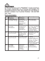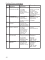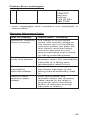
1
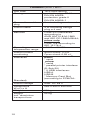
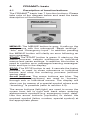
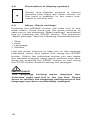
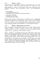
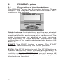
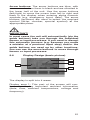
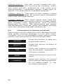
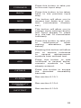
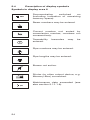
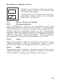
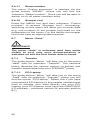
FRIAMAT® prime
FRIAMAT® basic
FRIAMAT®
Operating Instructions
1. Safety
5
1.1
1.2
1.3
1.4
1.5
1.6
1.7
1.8
1.9
1.10
5
5
6
7
7
7
9
9
9
9
Dangers
Safety hints and tips
Designated equipment use
Sources of danger
Authorised users
Dangers from electric power
Emissions
Safety precautions on site
Signal equipment
Emergencies
2. Basic Data
2.1
2.2
2.3
2.4
2.5
2.6
2.7
2.8
Design/parts
Operating principle
Ventilator function
Technical Data
Automatic activation of
“service interval”
Transport/storage/despatch
Setting up/connecting
Operating
3. Basic “Fusion” Procedure
3.1
3.2
3.3
Preparation
Enter barcode
Starting fusion process
4. FRIAMAT® basic
4.1
4.2
4.3
4.4
4.5
Description of function buttons
Description of display symbols
Menu “Basic settings”
Menu “Info”
Menu “Emergency input”
5. FRIAMAT® prime
5.1
5.2
5.3
5.4
5.5
2
Description of function buttons
Display Design (basic picture)
Description of display functions
Description of display symbols
Menu “Basic settings”
5.5.1 Documentation
5.5.2 Time
5.5.3 Date
5.5.4 Language
5.5.5 Protocol language
5.5.6 Volume
5.5.7 Remote control
9
9
10
10
11
13
13
13
14
14
14
15
16
17
17
18
18
19
19
20
20
21
22
24
25
25
25
25
26
26
26
26
5.6
Menu “Fusion sequence”
5.6.1 Commission number
5.6.2 Operator pass
5.6.3 Info text
5.6.4 Comment 1
5.6.5 Comment 2
5.6.6 Subcontractor
5.6.7 Traceability
5.6.8 Pipe number
5.6.9 Pipe length
5.6.10 GPS data
5.6.11 Seam number
5.6.12 Scraper tool
5.7 Menu “Data”
5.7.1 Transfer
5.7.1.1
PC/Laptop
5.7.1.2
Memory Box
5.7.1.3
Memory Card
5.7.1.4
Memory Stick
5.7.2 Printer
5.7.3 PDF
5.7.3.1
Memory Card
5.7.3.2
Memory Stick
5.7.4 CSV
5.7.4.1
Memory Card
5.7.4.2
Memory Stick
5.7.5 Delete
5.8 Menu “Info”
5.9 Menu “Formatting”
5.10 Fusion Options
5.10.1 ID-data
5.10.1.1 Commission number
5.10.1.2 Operator pass
5.10.1.3 Continuous number
5.10.1.4 Seam number
5.10.1.5 GPS 1 - 3
5.10.2 Traceability barcodes/
pipe number/pipe length
5.10.3 Info text, Comment 1,
Comment 2, Subcontractor
5.10.4 Emergency input
5.10.5 Scraper tool
5.11 SUPERVISOR
5.11.1 Basic settings
5.11.1.1 Documentation
5.11.1.2 Time
5.11.1.3 Date
5.11.1.4 Data protection
5.11.1.5 Memory Card
27
27
27
28
28
29
29
29
29
29
29
30
30
30
30
30
31
31
31
31
32
32
32
33
33
33
33
34
34
35
35
35
36
36
36
37
37
38
38
39
39
40
40
40
40
40
41
3
5.11.2
5.11.3
5.11.4
5.11.5
5.11.1.6 Maintenance date
5.11.1.7 Mode
5.11.1.8 Language
5.11.1.9 Emergency input
5.11.1.10 Energy display
5.11.1.11 Volume
5.11.1.12 Remote control
Fusion sequence
5.11.2.1 Traceability
5.11.2.2 Commission number
5.11.2.3 Infotext
5.11.2.4 Seam number
5.11.2.5 Continuous number
5.11.2.6 Operator pass
5.11.2.7 Display
“Pipe prepared”
Factory settings
PIN
Display (Resistance)
6. Warranty/Maintenance/
Taking out of Service
6.1
6.2
6.3
Warranty
Service and maintenance
Taking out of service
7. Operating Faults
7.1
7.2
7.3
4
44
44
44
45
45
45
45
46
46
Errors when reading in the barcode
46
Fusion interruption
46
Error messages/Warning messages/Info 46
8. Appendix
8.1
8.2
8.3
41
42
42
42
42
42
42
43
43
43
43
43
43
44
Recommended accessories (options)
Authorised service points
Operating instructions updates
51
51
51
51
1.
Safety
1.1
Dangers
FRIAMAT® fusion units have been designed using
state of the art technology and are constructed
according to ISO 12176-2 and recognised safety
regulations and fitted with appropriate protective
equipment. In addition FRIAMAT® fusion units have
been submitted to extensive tests in line with the
German law for equipment safety. Functionality and
safety of FRIAMAT® fusion units are tested before
they are supplied to the customer. However, incorrect use or abuse of the equipment will lead to
dangers with regards to:
- the health of the user,
- your FRIAMAT® model or other material goods by
the operator,
- the efficient operation of your FRIAMAT® model.
Everybody involved with operating, servicing and
maintaining your FRIAMAT® model must:
- be qualified accordingly, and
- carefully observe these instructions.
This is about YOUR safety!
1.2
Safety hints and tips
These operating instructions use the following
SYMBOLS with WARNING NOTES:
DANGER!
Warns of impending danger!
Non-compliance with this instruction can result in
severe material damage or personal injury.
WARNING!
Warns of a dangerous situation!
Non-compliance with this instruction can result in
moderate material damage or personal injury.
5
IMPORTANT!
Indicates user advice and other useful information.
1.3
FRIAMAT
fusion of
Designated equipment use
®
fusion units serve exclusively for the
- FRIALEN® safety fittings with HD-PE pressure
pipes (SDR 17-7), and
- FRIAFIT® sewage fittings with HD-PE sewage
pipes (SDR 17-32).
Your FRIAMAT® model can also be used to process
fittings by other manufactures as long as these are
provided by the manufacturer with a barcode 2/5
interleaved according to ANSI HM 10.8M-1983 and
to ISO CD 13950/08.94.
The designated use also includes observation of:
- all the advice in these operating instructions, as
well as
- the guidelines by DVGW Standards, DVS, UVV
and local directives.
IMPORTANT!
Any other use is not in line with designated use!
FRIATEC AG does not accept liability for damage
caused by adverse use:
- modifications and alterations are not permitted
for safety reasons.
- FRIAMAT® fusion units may be opened only be
electrical specialists.
- when carrying out fusions using FRIAMAT® fusion
units with broken lead seals will result in all claims
for warranty and liability being null and void.
6
Examples of adverse use:
- use as battery charger.
- use as power supply for heaters of any type.
1.4
Sources of danger
- replace damaged connection and extension
cables immediately.
- do not remove or disable safety devices.
- rectify known faults immediately.
- do not leave your FRIAMAT® model unattended.
- keep away from flammable liquids/gases.
- do not operate in EX environment.
1.5
Authorised users
Only trained personnel may work using your
FRIAMAT® model. The user is responsible for third
parties in the work area. The user must:
- make accessible the operating instructions to the
operator and
- ensure that he or she has read and understood
them.
1.6
Dangers from electric power
- do not use any damaged connecting cables.
- check connection cable for any damage.
- pull out the plug prior to any maintenance or
service tasks.
- allow any service and repairs to be carried out
only at authorised service points.
- connect fusion units of the FRIAMAT® range only
to supply voltage as given on data plate.
DANGER!
Distribution points on the construction site:
observe regulation on circuit breakers!
Outdoors (on construction sites) receptacles must
be fitted with earth leakage circuit breakers. When
using generators, the DVGW worksheet GW308, the
VDE 0100 Part 728 and specific local directives need
to be observed. The required generator nominal
output depends on the output required by the
largest fitting to be used, on connection conditions,
7
ambient conditions and the actual generator type
(its control characteristics). As the generators from
different model ranges often display very different
control characteristics, the suitability of a generator
cannot be guaranteed by the specified rated output
alone.
When in doubt (e.g. when purchasing brand new)
contact an authorised service point or call the
FRIATEC service hotline (+49 (0) 621 486 1533).
Only use generators working with frequencies within
the 44-66 Hz range.
Start up the generator and leave it running for half a
minute. If necessary adjust off-load voltage and limit
to voltage indicated by the technical data. Generator (power) fuse at least 16 A (slow acting).
WARNING!
Check input voltage of your FRIAMAT® model
before starting the fusion process. Your
FRIAMAT® model has been designed for input
voltage of 190-250 volt.
When using an extension cable, please ensure
sufficient cross section:
- 2.5 mm2 up to 50 m
- 4 mm2 up to 100 m length.
Always roll out cable fully before use! Do not
connect any other equipment to the same generator
while fusion is taking place! At the end of the fusion
process, first disconnect the power cable from the
generator and then shut off the generator.
DANGER
Danger to life! Never open your FRIAMAT® model
whilst connected to power supply!
FRIAMAT® fusion units may be opened only by
specialist personnel at an authorised service point!
8
1.7
Emissions
The (equivalent) continuous sound pressure level of
all FRIAMAT® fusion units is less than 70 db(A).
When working in a quiet environment, the signal
when set to “loud” comes across as very loud. For
this reason it is possible to adjust the signal (loud/
quiet).
1.8
Safety precautions on site
WARNING!
FRIAMAT® fusion units are splash proof. They
may however not be immersed in water.
1.9
Signal equipment
®
FRIAMAT fusion units confirm certain operating
procedures using a signal (1, 2, 3 or 5 signal sounds).
The signals signify the following:
1 signal:
2 signals:
3 signals:
5 signals:
reading in of barcode confirmed.
fusion process completed.
supply voltage too low/too high.
warning: error. Refer to display.
1.10
Emergencies
In an emergency switch off main switch immediately
to the “OFF” position and disconnect your FRIAMAT®
model from the power supply. FRIAMAT® fusion units
can be shut off by:
- activation of main switch or
- pulling out the power supply plug.
2.
Basic Data
2.1
Design/parts
All electronic parts of your FRIAMAT® model are
kept in splash proof casing. A receptacle for the
fusion and mains cable is situated at the back. At
the front there is an accessory shelf at the top; at
the side on the right is the interface space.
FRIAMAT® fusion units are designed for maximum
fusion voltage of 48 V. A safety transformer separates supply and fusion voltage.
9
2.2
Operating principle
Only electrical fusion fittings with a barcode can be
welded using FRIAMAT® fusion units: a sticker with
a barcode is allocated to each fitting. It contains
information for the correct fusion process. Your
FRIAMAT® model boasts a PC supported command
system which:
- controls and adjusts energy supply fully
automatically, and
- determines the length of the fusion process,
taking into account ambient temperature. The
temperature gauge inside the fusion cable
continuously measures the ambient temperature.
WARNING!
The temperature gauge for determining the
ambient temperature is attached to the fusion
cable at the reader wand cable near the reader
wand pouch (silver metal sleeve). As the
determination of the ambient temperature in the
fusion zone is part of a correct fusion process,
the temperature gauge must be protected from
damage at all cost. In addition you need to make
sure that both the temperature gauge as well as
the fitting to be welded are exposed to identical
ambient temperatures, i.e. processing situations
where e.g. the temperature gauge is exposed to
bright sunlight and the fitting is in the shade
must be avoided.
2.3
Ventilator function
Below the carrying handle there are ventilation slots.
The main switch is located in the centre. A fan each
is located to the right and left of the main switch
below the ventilation slots.
Fundamentally, the ventilators start up automatically
at each fusion (please refer to IMPORTANT note
below). It is their job to suck in air around the fusion
and mains cable outlets (bottom of back) and to
blow this air back out through the airing slits at the
top. The air in this direction of flow cools the cooling
device which is spread across the entire width of
the back below the casing. This means that the
10
electrics responsible for the output of your
FRIAMAT® model are cooled and your unit is now
well equipped to meet the demands of the
construction site (e.g. a series of fusion processes
of different fittings).
IMPORTANT!
The long-term ventilator function depends on the
internal temperature being gauged at the heat
sink; i.e. once a specified temperature has been
reached, the ventilators automatically switch
themselves on. This means that the ventilators
work permanently – depending on the load on
your FRIAMAT® model – (not only during but also
before and after the next fusion process). When
you give your unit “a break” (switch it off), it is
possible that the ventilators start up immediately
once the unit is switched on again (depending on
previous workload), as the heat sink has not yet
cooled down below the given temperature limit.
IMPORTANT!
Leave the unit switched on after a fusion process
allowing the ventilators to lower the temperature
of the cooling device.
2.4
Technical Data
FRIAMAT® prime / basic*
Input voltage range
Frequency range
Current consumption
Output
Generator rated
output for fittings
d 20 – d160
d180 – d710
(adjusted
mechanically)
d180 – d710
(adjusted
electronically)
AC 190 V – 250 V
44 Hz...66 Hz
AC 16 A max.
3.5 kW
~ AC 2.4 kW
~ AC 4.0 kW
~ AC 5.0 kW
11
FRIAMAT® prime / basic*
Unit fuse
Casing
Connection cable
plug
Fusion cable
Barcode
Operating
temperature range
Fusion current
monitoring
Interfaces
Standard)
Fusion voltage
Dimensions
WxDxH
Weight
Weight
incl. aluminium
transport box
12
16 A slow acting
protection type IP 54
DIN EN 60529
protection grade II
DIN EN 60335-1
5 m including contoured
4 m including fittings
plug ø 4 mm
Code 2/5 interleaved
according to
ANSI HM 10.8 M-1983
and ISO CD 13950/08.94;
prime only:
Code 128 according to
ISO 12176-4
-20°C...+50°C**
Short circuit 110 A
Open circuit 0,25 x IN
basic:
* serial
prime:
* serial
* parallel printer interface
(D-Sub 25)
* 2 USB interfaces:
USB A
USB B
* Memory-Card Slot
(according to PCMCIAmax. DC 48 V
285 x 450 x 450 mm
13 kg
22 kg
*: We reserve the right to make technical
alterations.
**: When fusing fittings by other manufacturers it
is vital to observe indications regarding
operating temperature range!
2.5
Automatic activation of
“service interval”
Starting with the first fusion process which you
perform with the new FRIAMAT® fusion unit, the
stored service interval (see also Chapter 6.2) is
auto matically set to active (recommendation
FRIATEC: 12 months).
IMPORTANT!
The leading service date is always shown on the
display and may deviate from the service label
attached to the FRIAMAT® fusion unit.
2.6
Transport/storage/despatch
Your FRIAMAT® model is delivered in an aluminium
transport box. Unpacking requires no specific skills,
nor does storage in the transport box. The temperature range during storage is -20°C.....+70°C.
WARNING!
Always transport/store inside aluminium transport box.
2.7
Setting up/connecting
Your FRIAMAT® model can be set up and operated
out of doors if protected from rain and wet.
- Set up you FRIAMAT® model on level ground (as
near level as possible).
- Ensure that the used generator is fused with a 16
A minimum (slow acting) fuse.
- Plug unit connection cable into power socket.
- Use extension cable if necessary, ensure sufficient
cross section (see also Section 1.6).
- Observe operating instructions of generator if
used.
13
WARNING!
Always unwind all cables completely before use!
2.8
Operating
WARNING!
Charring! Dirty contacts may char the plug.
Contact surfaces of fitting and fusion plug must be
clean at all times:
- thoroughly remove any existing deposits.
- protect plug from contamination, replace if
necessary.
- check fusion plug and contact sockets of the
fitting for dirt before connecting.
3.
Basic “Fusion” Procedure
3.1
Preparation
The appropriate assembly instructions need to be
observed for the correct processing of FRIALEN®
safety fittings and FRIAFIT® sewage system. The
same applies for fittings by other manufacturers.
IMPORTANT!
Unwind cables completely!
This applies to power cables, fusion cables, and
extension cables if required. The contact
surfaces of the fitting and the fusion plugs must
be clean; dirty contacts can cause overheating
and charring of the plug. If necessary carefully
remove any existing deposits. Always protect
plugs from contamination. If there is evidence of
a deposit which cannot be completely removed,
the fusion plugs must be replaced.
14
- prepare fitting and pipes for fusion in accordance
with assembly instructions.
- ensure that the contact pins on the fitting are
accessible for connection of fusion plugs.
- connect to power supply (mains or generator).
- If using a generator, start it first and leave to warm
up for 30 seconds.
- switch on unit by the main switch.
- connect fusion plug with contact pins of the fitting.
3.2
Enter barcode
WARNING!
Take reader wand out of reader wand pouch by
opening the pouch, grasping the reader wand at
its end/anti-kink sleeve (black) and taking it out.
It is not permitted to read in the barcode of a
different type of fitting. On completion of the
reading in process the reader wand must be
returned to its pouch immediately in order to
avoid damage and contamination of the reader
wand tip.
IMPORTANT!
Please also ensure that the fusion plugs of your
FRIAMAT® model are attached to the contact
pins on the fitting across the entire internal
contact width.
Once the barcode label has been attached to the
fitting, this is the only one to use. If the barcode
label of the fitting to be fused is not legible due to
damage, a fitting with a legible barcode label built
in the same way by the same manufacturer must
be used.
Hold the reader wand slightly slanted and slightly
inclined (like a pencil) and place it on the fitting in
front of the barcode. Now move the reader wand
quickly across the whole label and a little way
beyond. The reading can be done from right to left
or the other way around. If this has been done
correctly, the device will confirm the reading with a
signal. If reading in is not successful straight away,
try again, if necessary at a different angle or speed.
15
3.3
Starting fusion process
WARNING!
If there is a malfunction in the fusion process hot
molten PE may be expelled on rare occasions.
Therefore:
Maintain a safety distance of at least 1 m from
the fusion point during fusion! Do not connect
any additional equipment during fusion.
The fusion process can be cancelled at any time by
pressing the STOP button. When the fused area has
cooled down (and the source of the fault eliminated
where necessary) the fusion process can be
repeated (depending on the fitting manufacturer,
please observe operating instructions by the
appropriate fitting manufacturer).
Operating steps:
1. Display prompts “pipe prepared?”, confirm if yes.
2. Press the START button to start the fusion
process. Now follow automatic checks of the
ambient temperature and resistance check of the
fitting connected. Fusion starts. The display will
tell you the duration of the fusion (it will show
total time of fusion and count it up in seconds).
3. Display “end of fusion” means that the fusion
process has been completed. Displays “t” and
“tc:” show reference and actual fusion time and
must be identical.
4. Mark fusion parameters on pipe/fitting. This will
make sure no second fusion is accidentally carried out.
5. Display „end of fusion“ with “t” and “tc:” is
necessarily to confirm by pressing the STOP
button. For the FRIAMAT prime the guide button
“OK” can be pushed alternatively. Thus, the
fusion process has been completed and the
FRIAMAT® fusion unit is ready for the next fusion.
16
4.
FRIAMAT® basic
4.1
Description of function buttons
The FRIAMAT® basic has 7 function buttons. Please
take note of the diagram below and read the basic
description of the buttons.
MENUE: The MENUE button is grey. It calls up the
main menus with the submenus “Basic settings”,
“Info” and “Emergency input”. In addition pressing
the MENUE button will clarify an error following an
error message.
START: The START button is green. It starts up the
fusion process, selects submenus or individual
menus and saves settings. In addition this button is
used to confirm error messages/warning messages/
hints and tips in the display.
STOP: The STOP button is red. It cancels the fusion
process, is used to close submenus or individual
menus and stop the entering process (without
saving data).
Arrow buttons: The arrow buttons are blue. The
arrow buttons (up/down) are used to “browse”
through sub or individual menus. The display will
show you by means of a special symbol where such
“browsing” is possible (refer to section 4.2).
The arrow buttons (left/right) are used to move the
curser from left to right and back when entering
alphanumeric symbols (e.g. emergency input, date).
Use the arrow buttons (up/down) to select the
required symbol (letter, number, special symbol) at
the appropriate place.
17
4.2
Description of display symbols
Where this display symbol is shown
(second line) there are other menus on
this level in addition to the menu indicated in the first line.
4.3
Menu “Basic settings”
Pressing the MENUE button will take you to the
main menu. Once there use the arrow buttons to
take you to the submenu “Basic settings” and select
this by pressing the START button. The submenu
“Basic settings” has the following individual menus:
•
•
•
•
Time
Date
Language
Volume
Use the arrow buttons to take you to the required
individual menu and select this using the START
button. Within the individual menus you can make
the desired changes using arrow buttons and save
these by pressing the START button or exit using
the STOP button without saving the changes.
IMPORTANT!
The language setting menu displays two
asterisks right and left in the top line. These
serve to identify the language setting menu if the
language has been accidentally changed.
18
4.4
Menu “Info”
Pressing the MENUE button will take you to the
main menu. Use the arrow buttons to take you to
the sumenu “Info” and select this by pressing the
START button. The submenu “Info” is subdivided
into:
•
•
•
•
•
•
time/date
voltage/frequency
temperature (ambient temperature)
device number
software version
maintenance date
Use the arrow buttons to select the required
individual menu and select this using the START
button. Within this individual menu you can access
the information you requested and leave each menu
by pressing either the START or the STOP button.
4.5
Menu “Emergency input”
By pressing the MENUE button you will access the
main menu. From there find the submenu
“Emergency Input” using the arrow buttons and
select it by pressing the START button.
Now “Code:” is displayed and 24 numbers with the
first one flashing (when accessing this for the first
time all the digits will be set to “0”, afterwards the
most recently manually entered barcode is
displayed). Enter the numbers displayed on the
barcode of the fitting to be fused. Once the numbers
have been entered using the arrow buttons, you
must confirm this by pressing the START button; if
you press the STOP button the process will be
stopped (without saving data).
19
5.
FRIAMAT® prime
5.1
Description of function buttons
The FRIAMAT® prime has 9 function buttons. Please
observe the diagram below and the basic description of the buttons.
Guide buttons: Guide buttons are blue, are situated
at the very top of the unit (directly below the
graphical display) and have a grey background. The
guide buttons are not labelled as their functions
vary according to input and are displayed in the
bottom line of the graphical display (see section 5.2
and 5.3).
START: The START button is green. The START
button is used to start up the fusion process.
STOP: The STOP button is red. The STOP button is
used to cancel the fusion process and generally to
stop input (without saving data). When terminating
input by using the STOP button you will always be
taken back to the basic picture of the graphical
display (reset function).
20
Arrow buttons: The arrow buttons are blue, with
arrows marked on them in black and are situated in
the lower half of the unit. Use the arrow buttons
(left/right) to move the cursor from left to right and
back in the display when entering alpha numeric
symbols (e.g. emergency input, date). The arrow
buttons (up/down) are used to select the required
symbol (letter, number, special symbol) at the
appropriate place.
IMPORTANT!
In most cases the unit will automatically (via the
guide buttons) take you through the individual
menus or input processes. If you need to disrupt
this automatic process (e.g. because you made
a mistake at a previous input step) and/or the
guide buttons are used up by other functions,
you can use the arrow buttons to move through
menus or input processes.
5.2
Display Design (basic picture)
2
1
3
4
The display is split into 4 areas:
Display area 1: This part of the screen will continuously display important ambient information
(date, time, ambient temperature, voltage and
frequency).
21
Display area 2: This part of the screen will continuously display the functions as symbols, which
you have actively selected at this point (e.g.
documentation, traceability mode). Refer also to
section 5.4 “Description of display symbols”.
Display area 3: This part of the screen (“main
window”) will display all entries and information
within the individual menus.
Display area 4: The three black text bars are
allocated to the blue guide buttons situated below
and change their description and function
depending on input. The descriptions are largely
self explanatory and will guide you safely through
your input process (see also section 5.3).
5.3
Description of display functions
The function of the black text bars allocated to the
blue guide buttons changes in line with input.
However, due to the intelligent basic design of the
menus, only few terms (or functions) are used:
MENUE
Press this button to take you
to the main menu.
SELECT
Press this button to select a
submenu.
OK
Press this button to confirm
the information displayed in
the main window.
SAFE
Press this button to save your
input.
CANCEL
22
Press this button to cancel
input without saving data and
to be taken back to the
previous input step.
FORWARD
Press this button to take you
to the next input step.
BACK
Press this button to be taken
back to the previous input
step.
NEW
CHANGE
SHIFT
REMOVE
ADD
DETAILS
ID-DATA
EMERGENCY
INPUT
INFOTEXT
This button will allow you to
rename text fields (e.g. infotext, commission number,
etc.).
This button will allow you to
change menu settings and/or
text input already in place
(e.g. the last 10 commission
numbers).
Press this button to take you
to
“add/remove”
when
making
alterations
(see
below).
Pressing this button will allow
you to remove individual
or
several
alphanumeric
symbols from entered text.
Press this button to add
invididual or several alphanumeric symbols to text
already entered.
Press this button to access
the decoded traceability
barcode.
See section 5.10.1.
See section 5.10.4.
See section 5.10.3.
23
5.4
Description of display symbols
Symbols in display area 2
Documentation
switched
on
(including indication of remaining
memory space).
Seam numbers may be entered.
Current number not sorted by
commission number; numbers run
consecutively.
Traceability
entered.
barcodes
may
be
Pipe numbers may be entered.
Pipe lengths may be entered.
Buzzer not active.
Printer (or other output device, e.g.
Memory-Box) connected.
Maintenance date exceeded (see
also section 5.11.1.6).
24
Symbols in display area 3
Blank box indicates that the appropriate menu point or function has
not been activated.
Checked box indicates that the appropriate menu point or function
has been activated.
5.5
Menu “Basic settings”
5.5.1
Documentation
Your FRIAMAT ® model is supplied with the
documentation function switched off. The function
“Documentation” serves to save fusion parameters.
These may be allocated either to an commission
number and/or a operator pass. Via the guide button
“Menu” you will access the menu “Basic settings”
with its submenu “Documentation”. In this menu it
is possible to switch documentation on or off.
5.5.2
Time
The guide button “Menu” will take you to the menu
“Basic settings” with its submenu “Time”. There
you will be able to change the time in this menu.
5.5.3
Date
The guide button “Menu” will take you to the menu
“Basic settings” with its submenu “Date”. There you
will be able to change the date in this menu.
25
5.5.4
Language
Press the function key “Menu” to access the menu
“Basic Settings”. The menu includes the sub-menu
“Language”. By pressing the corresponding function
keys, you can select your desired language shown
in the display in this menu.
IMPORTANT!
The menu “Language” is identified by two
asterisks (one asterisk to the left of the term
“Language” and one asterisk to the right). These
asterisks serve to be able to identify the
language setting menu in case the language has
accidentally been changed.
5.5.5
Protocol language
Press the function key “Menu” to access the menu
“Basic Settings”. The menu includes the sub-menu
“Protocol language”. By pressing the corresponding
function keys, you can select the desired language
of the documentation in this menu.
IMPORTANT!
The protocol language can be set independent
of the language on the display.
5.5.6
Volume
Use the guide button “Menu” to get to the menu
“Basic settings” with its submenu “Volume”. There
you can set the volume in this menu to either “loud”
or “quiet”.
5.5.7
Remote control
Use the guide button “Menu” to get to the menu
“Basic settings” with its submenu “Remote Control”.
This menu is only to be used if you work with a
remote control of FRIATEC. More information you
will find in the operating manual “Remote control”.
26
5.6
Menu “Fusion sequence”
IMPORTANT!
The menu “Fusion sequence” is activated (and
thus visible to you) when the documentation has
been switched on. All submenus are not
activated on delivery (factory setting) as a point
of principle.
Press the MENU button to select the main menu.
Use the arrow buttons (up/down) to access the
submenu “Fusion Process” and select by pressing
the START button.
5.6.1
Commission number
The menu “Fusion sequence” is reached via the
guide button “MENU”. There you will find the
submenu “Commission number”. There you will be
able to switch on or off working with commission
numbers. On selecting “Commission number” the
commission number “########################”
will appear in the main screen in the top line next to
“➔ CODE”.
5.6.2
Operator pass
IMPORTANT!
The menu “Operator pass” is activated (and thus
visible to you) only once an operator pass has
been read in – with the documentation switched
on. You can order operator passes from
FRIATEC. Once an operator pass has been read
in, all fusion processes carried out will be saved
under the code of this operator pass. By reading
in a different operator pass your FRIAMAT®model will be switched over accordingly.
27
IMPORTANT!
Once you have read in the operator pass you will
automatically be taken to submenu “ID Data”
(see also Section 5.10.1). By moving the blue
arrow buttons (up/down) you will be given an
overview of the settings that have been selected
on your FRIAMAT ®-model. Press the STOP
button to exit this submenu.
IMPORTANT!
By means of the operator pass your FRIAMAT®model can be blocked to prevent it from
unauthorised use. After repeated reading in of the
current operator pass the question will be posed
“BLOCK UNIT?”. Then you can confirm this or
cancel the action. Your FRIAMAT®-model will be
blocked automatically when the code of an
operator pass is on file and there has been a
change of date, i.e. your FRIAMAT®-model is
blocked the next day. In both cases (manual or
automatic blocking) the following message
appears in the display “OPERATOR ➔ CODE”. By
reading in an operator pass your FRIAMAT®model is once again cleared for use.
5.6.3
Info text
Press the MENU button and then submenu “Fusion
process” to access “Info text”. Activating/switching
on this menu will allow you to include additional text
information to a fusion process.
5.6.4
Comment 1
Press the MENU button and then submenu “Basic
setting” to access “Comment 1”. Activating/
switching on this menu will allow you to include
additional text information to a fusion process.
28
5.6.5
Comment 2
Press the MENU button and then submenu “Fusion
process” to access “Comment 2”. Activating/
switching on this menu will allow you to include
additional text information to a fusion process.
5.6.6
Subcontractor
Press the MENU button and then submenu “Fusion
process” to access “Subcontractor”. Activating/
switching on this menu will allow you to include
additional text information to a fusion process.
5.6.7
Traceability
The guide button “Menu” will take you to the menu
“Fusion sequence”. The submenu “Traceability” can
be found there. There you will be able to release in
this menu your FRIAMAT® prime for reading in,
processing and saving of traceability barcodes. In
addition submenus “Pipe number” and “Pipe
length” are activated when this menu is accessed.
5.6.8
Pipe number
Press the MENU button and then submenu “Fusion
process” to access “Pipe number”. Activating/
switching on this menu will allow you to allocate an
individual pipe number to the pipes to be fused.
5.6.9
Pipe length
Press the MENU button and then submenu “Fusion
process” to access “Pipe length”. Activating/
switching on this menu will allow you to add the
length of the pipes to be fused.
5.6.10
GPS data
Press the MENU button and then submenu “Fusion
Process” to access “GPS data”. Activating/
switching on this menu will allow you to enter
coordinates/position of your fusion fitting. To
determine the GPS data you will need an
appropriate device.
29
5.6.11
Seam number
The menu “Fusion sequence” is reached via the
guide button “MENU”, where you will find the
submenu “Seam number”. There you will be able to
switch on or off seam numbers entry.
5.6.12
Scraper tool
Press the MENU key and then submenu “Fusion
process” to access “Scraper tool”. Activating/
switching on this menu will allow you to enter data
(e.g. unit number) of the scraper tool used for the
preparation of the fusion. For this facility the scraper
tool must have an appropriate barcode.
5.7
Menu “Data”
IMPORTANT!
The menu “data” is activated (and thus made
visible to you) only once documentation is
switched on and the first fusion data is saved.
5.7.1
Transfer
The guide button “Menu” will take you to the menu
“data” with its submenu “Transfer”. The sections
below describe the various options to extract and
transfer saved data from your FRIAMAT® prime.
5.7.1.1
PC/Laptop
The guide button “Menu” will take you to the menu
“Data” with its submenu “Transfer” where you will
find the option “PC/Laptop”. Select this if you have
connected a PC/Laptop to the parallel interface and
wish to transfer your data directly into your PC/
Laptop (your PC/Laptop must have the FRIATRACE
5.3 software – minimum version IV; see also section
8.1).
30
5.7.1.2
Memory Box
The guide button “Menu” will take you to the menu
“Data” with its submenu “Transfer” where you will
find the option “Memory Box”. Select this if you
have connected your Memory Box (see also section
8.1) to the parallel interface and wish to transfer
your data.
5.7.1.3
Memory Card
The guide button “Menu” will take you to the menu
“Data” with its submenu “Transfer” where you will
find the option “Memory Card”. Select this if you
have connected your Memory Card (see also
section 8.1) to the card slot on FRIAMAT® prime and
wish to transfer your data (see also section 5.11.1.5).
IMPORTANT!
FRIATEC AG does not accept liability for the use
of any other PC cards (according to PCMCIA
standard). The Memory-Card has been designed
specifically for a “rough” environment.
5.7.1.4
Memory Stick
Press the function key “Menu” to access the menu
“Data”. In the sub-menu “Transfer” you will find the
option “Memory Stick”. You will make this selection
if you inserted your memory stick (see also Chapter
8.1) into the USB interface at your FRIAMAT® prime
and want to transfer your data.
IMPORTANT!
FRIATEC does not assume any liability if
commercially available USB flash drives are
used. Use your FRIATEC memory stick.
5.7.2
Printer
Press the function key “Menu” to access the menu
“Data”. The menu includes the sub-menu “Printer”.
You will make this selection if you connected your
printer to the parallel interface or USB interface and
want to print your data on paper.
31
5.7.3
PDF
Press the function key “Menu” to access the menu
“Data”. The menu includes the sub-menu “PDF”.
“PDF” is selected for outputting the data as pdf file.
The pdf files are written into a sub-directory on the
output device (see following Chapters 5.7.3.1 and
5.7.3.2) which has the following name: F+device
number (e.g. FR 13 81 001): F1381001
The file names are generated based on the present
date and a two-digit ascending number starting
from 0, e.g. 2nd hardcopy (02) on 1st February 2013
(130201): 13020102.PDF
Pdf files can be directly printed at the PC/laptop
with the corresponding software (e.g. Acrobat
Reader©).
IMPORTANT!
The pdf file cannot be transferred to the memory
box.
5.7.3.1
Memory Card
Press the function key “Menu” to access the menu
“Data”. In the sub-menu “PDF” you will find the
selection option “Memory Card”. You will make this
selection if you inserted your memory card (see also
Chapter 8.1) into the card slot at your FRIAMAT®
prime and want to output your data as a pdf file on
this output device.
5.7.3.2
Memory Stick
Press the function key “Menu” to access the menu
“Data”. In the sub-menu “PDF” you will find the
selection option “Memory Stick”. You will make this
selection if you inserted your memory stick (see
also Chapter 8.1) into the USB interface at your
FRIAMAT® prime and want to transfer your data as
a pdf file.
32
5.7.4
CSV
Press the function key “Menu” to access the menu
“Data”. The menu includes the sub-menu “CSV”.
“CSV” is selected for outputting the data as CSV
file. The CSV files are written into a sub-directory on
the output device (see following Chapters 5.7.4.1
and 5.7.4.2) which has the following name: F+device
number (e.g. FR 13 81 001): F1381001
The file names are generated based on the present
date and a two-digit ascending number starting
from 0, e.g. 2nd hardcopy (02) on 1st February 2013
(130201): 13020102.CSV
CSV files can be read and processed at the PC/
laptop with the corresponding software (e.g.
Microsoft® Excel).
IMPORTANT!
The CSV file cannot be transferred to the memory box.
5.7.4.1
Memory Card
Press the function key “Menu” to access the menu
“Data”. In the sub-menu “CSV” you will find the
selection option “Memory Card”. You will make this
selection if you inserted your memory card (see also
Chapter 8.1) into the card slot at your FRIAMAT®
prime and want to output your data as a CSV file on
this output device.
5.7.4.2
Memory Stick
Press the function key “Menu” to access the menu
“Data”. In the sub-menu “CSV” you will find the
selection option “Memory Stick”. You will make this
selection if you inserted your memory stick (see
also Chapter 8.1) into the USB interface at your
FRIAMAT® prime and want to transfer your data as
a CSV file.
5.7.5
Delete
Press the function key “Menu” to access the menu
“Data”. The menu includes the sub-menu “Delete”.
By pressing the corresponding function keys, you
can delete your stored data in this menu.
33
IMPORTANT!
If you deleted data, these will be irrevocably lost.
Based on the automatic back-up function of the
device, authorised FRIATEC service personnel
might be able to restore deleted data.
Please contact your local service station (see
Chapter 8.2).
5.8
Menu “Info”
The guide button “Menu” will take you to the menu
“Info”. Here you will find important information about
your FRIAMAT® prime: device number, software
version and next maintenance date. Make sure you
have this information with you when you approach
an authorised FRIATEC service point with questions
or problems.
5.9
Menu “Formatting”
Basically the FRIATEC Memory-Stick can be used
for the transfer of data. The FRIATEC Memory-Stick
can be purchased from FRIATEC.
If you have not used the FRIATEC Memory-Stick on
the FRIAMAT® prime and the correct format has
therefore not been set, or you decide to go for a
standard USB flash drive, please note that it must
be formatted to FAT 12 or FAT 16. A USB flash drive
formatted to FAT 32 or a partitioned USB flash drive
(Master Boot Record) will produce the error
message “ERROR 91” on your FRIAMAT®.
Formatting to FAT 12 or FAT 16 can be done in
submenu “Formatting”. Press the MENU button to
access the main menu. Use the arrow buttons (up/
down) to access submenu “Formatting” and select
by pressing the START button. On selecting menu
point “MEMORY-STICK” you will be asked “ARE
YOU SURE?” before formatting starts.
IMPORTANT!
Please note that all data is deleted from the
FRIATEC Memory-Stick during formatting!
34
IMPORTANT!
FRIATEC AG accepts no liability for the use of
standard USB flash drives. Please use the
FRIATEC Memory-Stick.
5.10
Fusion Options
5.10.1
ID-data
IMPORTANT!
The “ID-data” option is activated and visible to you
only once documentation has been switched on.
Once documentation has been switched on, the
function “ID-data” appears in the guide button bar
on the basic picture (see also section 5.2). This
includes data which you can allocate to your imminent fusion process: commission number, operator
pass, continuous number and seam number. The
following sections describe this additional
information.
IMPORTANT!
Entering commission numbers and seam
numbers is possible only when documentation
and function “Commission number” (see section
5.6.1) and/or “Seam number” (see section 5.6.11)
are switched on.
5.10.1.1 Commission number
Press the MENU button to access submenu
“ID-data”. Press the START button to bring
up “Commission Number” in the top line of
the display. On entering an commission number
for the first time the following appears
“########################”. The first digit
flashes. By moving the arrow buttons you will be
able to enter your commission number. Use the
START button to save this number and the STOP
button to exit the submenu.
35
If you have already entered one or several
commission numbers, you will be able to choose in
“ID-data” in submenu “Commission number”
between “CHANGE” (changing of last entered
commission number), “NEW” (entering a new
commission number), and “SELECTION” (selecting
an commission number from the last 20 commission
numbers entered) by pressing the START button
and using the arrow buttons (up/down). Data entry,
saving and exiting this submenu takes place as
described above.
5.10.1.2 Operator pass
By pressing guide button “ID-data” the main
window will indicate whether and which operator is
on file (if no operator pass has been activated, there
will be no indication in this window). The operator
can not be changed manually – i.e. via the buttons.
This means that you will require an operator pass to
put a new operator on file (see section 5.6.2).
5.10.1.3 Continuous number
By pressing guide button “ID-data” the continuous
number of the fusions carried out by you will be
indicated. This number is allocated automatically by
the unit and can not be changed. Normally the
continuous number is allocated to the appropriate
activated commission number; the SUPERVISOR
(see section 5.11) has the option of setting different
allocations (see section 5.11.2.5).
5.10.1.4 Seam number
By pressing guide button “ID-data” the main
window (display area 3, see also section 5.2) will
allow you to allocate a number chosen by you
(“seam number”) to your fusion process. If the
commission number input has been activated at the
same time, you will need to move from commission
number (on black) to the seam number (now on
black) by activating the arrow buttons down. By
activating the appropriate guide buttons you will
now be able to enter a seam number (“CHANGE”).
Select alphanumeric symbols using the arrow
buttons. Confirm your entry by pressing the guide
button “SAVE”. As this main window also allows
you to enter data regarding information on
commission number, operator pass and continuous
36
number (when activated) you will have to leave the
main window – once you have made all required
changes – by pressing the guide button “OK”.
5.10.1.5 GPS 1 - 3
Use the MENU button to access submenu „IDdata“. Press the START button and use the arrow
buttons (up/down) to access the screen where you
are able to enter the coordinates of the fusion
processes carried out by you (GPS 1, GPS 2 and
GPS 3). Symbols are chosen by using the arrow
buttons. Use the START button to save this number
and the STOP button to exit the submenu. You will
need an appropriate device for calculating the GPS
data.
5.10.2
Traceability barcodes/pipe number/
pipe length
IMPORTANT!
It is possible to enter traceability data only when
documentation and “traceability” function and/
or “pipe number and/or “pipe length” are
switched on (see section 5.6.7).
Traceability barcodes entry option is activated by
reading in the fusion barcode of the fitting to be
fused. A command to enter the traceability barcode
of the fitting will appear in the main window. Once
you have entered this (made visible by a tick in a
box), the display in the main window will “jump” to
the command for entering the traceability barcode
of component 1. When you have activated entry of
pipe number and/or pipe length, this will also be
indicated here and can be entered accordingly.
Once entered, the display in the main window will
change to the command for entering traceability
barcode of component 2. Enter pipe number and/or
pipe length the same way as described above. The
following display will remind you by asking “pipe
prepared?” to make absolutely sure that the pipe
has been scraped. By pressing “FORWARD” (i.e.
the pipe has been prepared appropriately) you will
reach the starting mode. Start the fusion process by
pressing the START button.
37
IMPORTANT!
Entering traceability data is fully automatic, i.e.
the display will show the next step on each entry
until you reach the starting point of the fusion
process. If you need or want to interrupt this
automatic process (e.g. because you want to
check your input once more), move around using
guide buttons “FORWARD” and “BACK” between
individual displays “fitting” / “component 1” /
“component 2” / “pipe prepared” / “start”. The
arrow buttons allow you to move within individual
windows.
5.10.3
Info text, Comment 1, Comment 2,
Subcontractor
Depending on your selections, the following will
appear as part of the data programming prior to
fusion “INFO TEXT”, “COMMENT 1”, “COMMENT
2” and/or “SUBCONTRACTOR”. By pressing the
MENU button and using the arrow buttons (symbol
selection) you will be able to add any additional
text. The lines will be blank initially, i.e. no additional
text is displayed (e.g. the text last entered). Use the
START button to save your entry and press it again
to continue preparing for your fusion.
IMPORTANT!
The additional text must be entered for each
fusion process, as no text will appear in the
report otherwise. If the START button is activated
immediately after reading in the fitting barcode,
no additional text is added to the fusion.
5.10.4
Emergency input
During the entering process of data in preparation
of the fusion process one of the guide buttons
comes up with the term “EMERGENCY INPUT”.
Press this to enter the individual window where you
will be able to enter the digits from each barcode.
The word “code” appears and the digits from the
most recently manually entered barcode (if this is
38
being done for the first time, no digits will appear).
The digits to be entered must be taken from the
barcode of the fitting to be fused. Select “NEW” to
delete the most recently entered barcode. You will
now be able to enter the new digits. Use “CHANGE”
to select the last barcode entered. Once entry (using
arrow buttons) or selection have been completed,
press the appropriate guide button, either “SAVE”
or “CANCEL”.
5.10.5
Scraper tool
As part of the process of entering data to start the
fusion the request “SCRAPER TOOL: ➔ CODE” – if
selected by you (see Section 5.6.12) – appears after
the prompt “PIPE PREPARED?”. If the scraper tool
which you used for the scraping of the pipe has the
appropriate barcode you will now be able to enter
this – this data will then be allocated to your fusion
in the report.
5.11
SUPERVISOR
The so-called SUPERVISOR has a supervisor pass
which allows him or her to carry out specific settings
on the FRIAMAT® prime, which due to their effect
on the unit’s properties and functions should be
done by one specific person only. The SUPERVISOR
needs to be familiar with the functions of the unit
and have fully understood the contents and effects
of the sections below.
The SUPERVISOR is able to configure the
FRIAMAT® prime in exactly the way he would like
the procedure to run on the construction site. This
means the unit can be set up to function quite
simply according to requirements (e.g. fusion
without documentation) or very complex indeed
(including documentation, traceability, seam
number, pipe number, pipe length, etc. ).
The main difference between this and the setting
options available to the user on the construction
site (see section 5.5 to 5.10) is that the SUPERVISOR has the option not only to carry out his
settings, but to block them to further changes, i.e.
the user on the construction site will not be able to
change the given settings and procedures.
39
IMPORTANT!
The settings/menus blocked by the SUPERVISOR will not be shown to the user on the
construction site (e.g. where documentation is
switched on and blocked at the same time to the
user, the menu “Documentation” disappears
from the menu bar).
The SUPERVISOR accesses the SUPERVISOR
menu by reading in the barcode on the
SUPERVISOR pass (this pass is purchased with the
FRIAMAT® prime). A PIN code will be requested.
The PIN code has been factory set to “0000” –
however, it is possible for the SUPERVISOR to set
his own PIN code combination, see also section
5.11.4).
5.11.1
Basic settings
5.11.1.1 Documentation
Select “Basic settings” to access submenu
“Documentation”. By activating the appropriate guide
buttons you will be able to switch documentation on
or off and block your settings from changes by users.
5.11.1.2 Time
Select “Basic settings” to access submenu “Time”.
By activating the appropriate guide buttons you will
be able to make the setting in in such a way that the
time can not be changed by the user.
5.11.1.3 Date
Select “Basic settings” to access submenu “Date”.
By activating the appropriate guide buttons you will
be able to make the settings in such a way that the
date can not be changed by the user.
5.11.1.4 Data protection
Select “Basic settings” to access submenu “Data
protection”. By activating the appropriate guide
buttons you will be able to limit the delete function
by blocking deletion through the user (data can not
be deleted) or by allowing the user to delete data
after print-out or transfer of data from the unit.
40
5.11.1.5 Memory Card
Select “Basic settings” to access submenu
“Memory Card”. By activating the appropriate guide
buttons you will be able to set your FRIAMAT® prime
in such a way that the Memory-Card is used as the
main memory. This means that the memory capacity
of your FRIAMAT® prime will be increased from
about 500 to approx. 30.000 fusion processes.
WARNING!
If the Memory-Card is used as the main memory,
the Memory-Card must be lodged permanently
in the card slot of the FRIAMAT® prime. If you
need to take the Memory-Card out (in order to
transfer the data to your PC) while the FRIAMAT®
prime continuous to operate, you will need a
second Memory-Card which can remain in the
FRIAMAT® prime. With this setting it is not
possible to work without Memory-Card in place!
If you do not carry out this setting, you will still be
able to use the Memory-Card to protect or transfer
data (e.g. you can use a Memory-Card to read data
from all your FRIAMAT® prime fusion units, i.e. the
Memory-Card is not lodged in the FRIAMAT® prime
and is inserted only for actual data transfer (see
also section 5.7.1.3). The memory of your FRIAMAT®
prime however is limited to about 500 fusions with
this procedure.
5.11.1.6 Maintenance date
Select “Basic settings” to access submenu
“Maintenance date”. By activating the appropriate
guide buttons you will be able either to deactivate
the warning “Maintenance date exceeded” (not
recommended, see section 6.2) or to set the unit in
such a way that it will stop carrying out fusions
once the maintenance date has passed. This setting
will also allow you, once the maintenance is
overdue, to make the “blocking” of the unit a little
less rigid by setting a period of between 0 and 99
days after “blocking” during which the unit will
continue to work after the date of the maintenance
has passed. This setting is shown to the user in the
41
display once the maintenance date has passed (as
the symbol of a screwdriver and the number of days
left for the unit to work).
5.11.1.7 Mode
Select “Basic settings” to access submenu “Mode”.
By activating the appropriate guide buttons you are
able to set international date and time formats as
well as temperature units.
5.11.1.8 Language
Select “Basic settings” to access submenu
“Language”. There you will be able to set the
required language, i.e. users will not be able to
change the language.
5.11.1.9 Emergency input
Select “Basic settings” to access submenu
“Emergency Input”. There you will be able to block
the option of entering barcode numbers manually
(not recommended, as work will have to cancel if
there is e.g. a damaged fusion barcode).
5.11.1.10 Energy display
Select “Basic settings” to access submenu “Energy
display”. There the amount of energy used is shown
to you (or not) after fusion is completed.
5.11.1.11 Volume
Select “Basic settings” to access submenu
“Volume”. There you will be able to set the volume
of the signal (on/off; loud/quiet) and block this
setting from any changes by the user.
5.11.1.12 Remote control
Select “Basic settings” to access submenu “Remote
control”. There you will be able to block the option
of working with remote control.
42
5.11.2
Fusion sequence
5.11.2.1 Traceability
Select “Fusion sequence” to access submenu
“Traceability”. There you will be able to switch on or
off the option to enter traceability barcodes, pipe
number and pipe length, and to block the selected
setting from any changes by the user.
5.11.2.2 Commission number
Select “Fusion sequence” to access submenu
“Commission number”. There you will be able to
switch on or off the option of working with
commission numbers. In addition you are able to
indicate (if you have opted for “On”) the need for
entering the commission number each time the unit
is switched on or before each fusion process. You
are also able to block your setting from any changes
by the user.
5.11.2.3 Infotext
Select “Fusion sequence” to access submenu “Infotext”. There you will be able to switch on or off the
option of entering up to four different text entries
(“infotext”, “comment 1”, “comment 2”, “operator”)
and to block the selected setting from any changes
by the user.
5.11.2.4 Seam number
Select “Fusion sequence” to access submenu
“Seam number”. There you will be able to switch on
or off the option of entering seam numbers and to
block the selected setting from any changes by the
user.
5.11.2.5 Continuous number
Select “Fusion sequence” to access submenu
“Continuous number”. There you will be able either
to allocate the continuous number (always given
out by the unit) to commission numbers (counting
takes place within the commission number, starting
with “1”) or to set to continuous, i.e. not relating to
the commission numbers.
43
5.11.2.6 Operator pass
Select “Fusion sequence” to access submenu
“Operator pass”. There you will be able to switch on
or off the option of working with the operator pass.
In addition you are able to deactivate the factory
setting (if you have opted for “On”), that the operator
pass must be read in once more when the date
changes (i.e. in the activated mode your unit will be
initially blocked the next day, until an operator pass
has been read in). In addition you are able to
inidcate that the operator pass must be read in
every time the unit is switched on and/or before
each fusion. You will also be able to block your
selected setting from any changes by the user.
5.11.2.7 Display “Pipe prepared”
Select “Fusion sequence” to access submenu “Display pipe prepared”. There you are able to switch
on or off the warning message which comes up
before fusion is started (switching off not
recommended).
5.11.3
Factory settings
In the “Factory settings” menu you will be able to
reset all settings made by you and/or the user; i.e.
FRIAMAT® prime will return to being configured the
same way it was delivered by the manufacturer
FRIATEC.
WARNING!
If you press “O.K.”, all your settings and text
entries will be lost.
5.11.4
PIN
The menu “PIN” allows you to change the number
combination “0000” for accessing the SUPERVISOR
menu as supplied by the factory. We recommend to
keep the number combination secret and not to
make the SUPERVISOR pass accessible to anybody. This is the only way to make sure that the
configuration set by you will not be changed.
44
WARNING!
Keep the number combination selected by you
secret and note it down in a place inaccessible
by others (in case you should forget the
combination). If you have lost or forgotten your
PIN, please contact our service hotline
+49 (0) 621 486 1533.
5.11.5
Display (Resistance)
In the menu “display” you can specify whether the
resistance actually measured at the fitting before
starting the fusion is to be indicated on the display.
The indication must then be acknowledged before
any fusion process by pressing the START key.
6.
Warranty/Maintenance/
Taking out of Service
6.1
Warranty
The warranty period for FRIAMAT® fusion units is
24 months.
6.2
Service and maintenance
According to DVS 2208 Part 1 or BGV A3 “Electrical
Plants and Devices” a maintenance of movable
electrical devices is to be performed at least once
a year (see list of the authorised service points in
section 8.2). Please observe any deviating, countryspecific regulations. Please include all connecting
adapters for service checks.
WHAT?
WHEN?
WHO?
cleaning
the reader
wand and
checking for
damage
daily
user
checking
function
weekly
user
cleaning
contacts
weekly
user
factory service
annually
authorised
service points
(see section 8.2)
45
6.3
Taking out of service
IMPORTANT!
FRIAMAT® fusion units contain different components which make specialist disposal necessary.
You FRIAMAT® model can be disposed of in the
factory or at one of the authorised service points.
7.
Operating Faults
7.1
Errors when reading in the barcode
If reading in is not confirmed by an acoustic signal
the reader wand should be checked for dirt or
damage. If the reader wand is damaged, fusion can
still be carried out using the Emergency Input Mode
(see Section 5.10.4).
7.2
Fusion interruption
If the fusion is interrupted, because e.g. the power
supply was disrupted during a fusion process, the
fusion can be repeated once the source of the fault
has been removed and the fitting has cooled off
completely (depending on manufacturer, please
observe operating instructions by the appropriate
fitting manufacturer).
7.3
Error messages/Warning messages/
Info
If irregularities occur during the fusion process, your
FRIAMAT® model will display the appropriate error
messages.
46
IMPORTANT!
In the event that your FRIAMAT® model displays
an error message or warning message not
described below and this cannot be clarified or
rectified based on the description in the display,
please contact our service hotline +49 (0) 621
486 1533.
Error messages:
No Text in
Display
Significance/ Remedy
Causes
02
Temperature
Ambient
Set up tent
outside range temperature if necessary.
outside
permitted
range.
03
Resistance
outside
tolerance
04
Fitting winding Short circuit Replace fitting,
short circuit
in the wire
send in for
winding of
checks.
fitting.
05
Fitting winding Current flow Check
open circuit
interrupted. connection of
fusion plug on
fitting. If okay
replace the
fitting and send
in for checks.
06
Voltage
outside
tolerance
Electrical
resistance
of fitting
outside
tolerance.
Non permitted
deviation of
fusion
voltage.
Check contact
for firm seating/
dirt. Maybe
clean contacts,
if necessary
replace fitting.
Contact
authorised
service point.
47
Further Error messages:
No Text in
Display
Significance/ Remedy
Causes
08
Mains voltage Power
outside range voltage
outside
permitted
range during
fusion.
Extension
cable too long
or cross
section too
small. Check
voltage and
connections of
generator.
09
Frequency
Frequency
outside range outside
permitted
range during
fusion.
Check
frequency of
generator
voltage.
10
Cancel of
fusion
Fusion inter- –
rupted by
pressing the
STOP button.
13
Mains failure
Supply
voltage
interrupted
(e.g.power
cut during
fusion) or
too low.
Check
connections.
15
Mains rating
exceeded
Power
consumption
of fitting
exceeds
rating of the
FRIAMAT®.
Please contact
FRIATEC
service
hotline:
+49 (0) 621
486 1533
23
Generator
failure
Generator
maybe not
suited for
fusion work.
Please contact
FRIATEC
service
hotline:
+49 (0) 621
486 1533
48
Further Error messages:
xy* System error
Please contact
FRIATEC
service
hotline:
+49 (0) 621
486 1533
*: error messages with numbers not displayed in
above table.
Warning Messages/Info:
Text in Display
Instruction / Remedy
Attention: Second
fusion process
If a fusion is to be fused
twice, the contact plugs on
the fusion unit of the fitting
must be pulled out after the
first fusion, and the fitting
must be allowed to cool
(see processing instructions
by fitting manufacturers).
Read in fusion
code first please
Only with prime: this
appears when the traceability
barcode of a fitting was
accidentally read in first.
Read in valid
traceability
barcode please
Only with prime: if e.g.
the fusion barcode of the
fitting was accidentally read
in.
Read in valid
operator pass
please
Only with prime: this
appears when the operator
pass needs to be read in
(e.g.when unit is blocked)
and/or a different (wrong)
barcode is read in.
49
Further Warning messages/Info:
Text in Display
Instruction / Remedy
Read in valid
commission
number please
Only with prime:
this appears when the
commission number needs
to be read in (e.g. when the
unit is set to reading in before
each fusion) and/or a faulty
takes place or a different
(wrong) barcode is read in.
Printer not ready
Only with prime:
check if output unit (PC/
laptop with FRIATRACE IV,
Memory-Box, Memory-Card,
printer) is connected properly.
Faulty/incorrect
barcode
Use new barcode of fitting
built in the same way or
correct using manually
entered code.
Unit blocked
Only with prime:
when maintenance is overdue
(see section 5.11.1.6).
Let the unit cool
down
Protective funcion designed
to prevent overheating of unit.
Switch unit off and leave to
cool until warning no longer
appears when switching it on
again.
Cancel of fusion
Fusion interrupted by
pressing STOP button.
End of fusion
Fusion completed.
Voltage ...V;
Frequency... Hz
Only with basic: adjust
generator and quit using
STOP button.
Memory empty
Only with prime: printing out
not possible if memory is
empty.
Memory full
Print out only prime
report.
Maintenance date
exceeded
Contact authorised service
point. Arrange for unit to be
serviced.
50
8.
Appendix
8.1
Recommended accessories (options)
- Memory-Card to save and transfer fusion data
and to output the data as pdf file (FRIAMAT® prime
only)
- Memory-Stick to save and transfer fusion data
and to output the data as pdf file (FRIAMAT® prime
only)
- Memory-Card station to transfer data from
Memory-Card to the PC (FRIAMAT® prime only)
- Memory-Box for transferring fusion data
(FRIAMAT® prime only)
- SUPERVISOR pass for individual adjusting of
menu functions (FRIAMAT® prime only)
- FRIATRACE IV for the electronic processing of
fusion data (FRIAMAT® prime only)
- Operator pass (FRIAMAT® prime only)
- Infrared remote control (FRIAMAT® prime only)
- Remote control pass
8.2
Authorised service points
Please contact our service hotline +49 (0) 621 486
1533 for details of service points world wide.
8.3
Operating instructions updates
These technical statements are regularly revised to
be up-to-date. The date of the last revision is stated
on the document.
For an updated version of the operating instructions,
please visit our website www.friatools.com on the
Internet. You will find the “Download” page on the
navigation bar. This page contains our updated
operating instructions as pdf documents. We will
also mail them to you on request.
51
52
2320a/6e · Update: 13.03.2012
FRIATEC Aktiengesellschaft
Technical Plastics Division
P.O.B. 71 02 61
D-68222 Mannheim
Telephone +49 621 486-1533
Telefax +49 621 479196
Internet: www.friatools.com
E-Mail: [email protected]