1
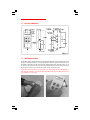
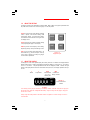
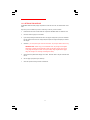
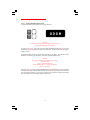
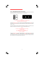
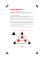
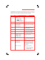
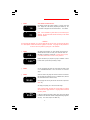
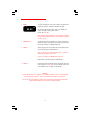
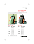
Instruction Manual
CHATILLON® DFIS Series
ACCUFORCE® AF2 Series
Digital Force Gauges
Operating Instructions
CHATILLON DFIS Series Digital Force Gauge
AMETEK AF2 Series Shown with MHTC
Mechanical Test Stand
-1-
NC001562
May 2001
Issue 3
TABLE OF CONTENTS
Page
INSTRUMENT PRECAUTIONS ..............................................................................................
4
1.0 INTRODUCTION AND PRODUCT OVERVIEW .........................................................
5
1.1 PRODUCT FEATURES ..................................................................................................
5
1.2 ELECTRICAL SAFETY ...................................................................................................
5
1.3 RECHARGING BATTERIES ...........................................................................................
5
1.4 PHYSICAL DIMENSIONS ................................................................................................
6
1.5 REVERSIBLE HOUSING .................................................................................................
6
1.6 ABOUT THE KEYPAD .....................................................................................................
7
1.7 ABOUT THE DISPLAY .....................................................................................................
7
1.8 CONNECTION TO EXTERNAL DEVICES ...................................................................
8
1.9 INTERFACE CABLES .....................................................................................................
9
1.10 SETTING UP FOR SAFE USE ......................................................................................
10
2.0 FRONT PANEL OPERATION .......................................................................................
11
2.1 NORMAL MODE ..............................................................................................................
11
2.1.1
Selecting Units of Measure ..............................................................................
11
2.1.2
Selecting Type of Measurement - Capturing Peaks .....................................
11
2.1.3
Zeroing ...............................................................................................................
12
2.1.4
Transmitting Readings .....................................................................................
12
2.2 CONFIGURATION MODE ...............................................................................................
13
2.2.1
Configuring Output Port- Analog Output ..........................................................
13
2.2.2
Configuring Output Port- Digital Outputs ..........................................................
13
2.2.2.1
Enabling the Mitutoyo Output ...................................................................
14
2.2.2.2
Enabling the RS-232 Port- Numerical Data Only ..................................
15
2.2.2.3
Enabling the RS-232 Port- Full Data .......................................................
16
2.2.2.4
Modifying Communication Parameters ..................................................
17
2.3 DATA COLLECT MODE ..................................................................................................
18
2.3.1
About Data Collect Mode .................................................................................
-2-
18
TABLE OF CONTENTS
Page
3.0 CALIBRATING THE DFIS/AF2 SERIES ....................................................................
20
3.1 CALIBRATION PROCEDURE ........................................................................................
20
4.0 DIAGNOSTICS ................................................................................................................
23
4.1 SOFTWARE PART NUMBER ........................................................................................
23
4.2 SOFTWARE REVISION LEVEL .....................................................................................
23
4.3 CAPACITY AND UNITS ..................................................................................................
24
4.4 NO LOAD ZERO VALUE .................................................................................................
24
4.5 RS232 LOOPBACK TEST ..............................................................................................
25
4.6 KEYPAD TEST .................................................................................................................
25
5.0 TECHNICAL REFERENCE AND SPECIFICATIONS ...............................................
26
6.0 MODEL NUMBERS ........................................................................................................
27
PRODUCT WARRANTY
This instrument is warranted against defects in workmanship, material and design for one (1) year from the
date of delivery to the extent that AMETEK will, at its sole option, repair or replace the instrument or any part
thereof which is defective provided, however, that the warranty shall not apply to instruments subjected to
tampering or abuse, or exposed to highly corrosive conditions.
THIS WARRANTY IS IN LIEU OF ALL OTHER WARRANTIES WHETHER EXPRESS OR IMPLIED AND
AMETEK HEREBY DISCLAIMS ALL OTHER WARRANTIES, INCLUDING, WITHOUT LIMITATION, ANY
WARRANTY OF FITNESS FOR A PARTICULAR PURPOSE OR MERCHANTABILITY. AMETEK SHALL
NOT BE LIABLE FOR ANY INCIDENTAL OR CONSEQUENTIAL DAMAGES, INCLUDING, BUT NOT
LIMITED TO, ANY ANTICIPATED OR LOST PROFITS.
This warranty is voidable if the purchaser fails to follow any and all instructions, warnings or cautions in the
instrument’s operation manual.
If a manufacturing defect is found, AMETEK will replace or repair the instrument or replace any defective part
thereof without charge; however, AMETEK’s obligation hereunder does not include the cost of transportation
which must be borne by the customer. AMETEK assumes no responsibility for damage in transit, and any
claims for such damage should be presented to the carrier by the purchaser.
-3-
PRECAUTIONS
q
Read the instruction manual completely before attempting to use the DFIS or ACCUFORCE
2 (AF2) Series. By following the instructions contained in this manual, the optimum accuracy and
performance can be attained.
IMPORTANT NOTE: The DFIS and ACCUFORCE 2 (AF2) gauges are identical in functionality. The procedures, specifications and operations in this manual apply to both products
unless noted.
q
Turn off the DFIS/AF2 Series before connecting or disconnecting any cables to the instrument.
q
Do not overload the DFIS/AF2 Series! The instrument can handle an overload of up to 150% of the
rated full scale. The display will read “- - - -” when the gauge exceeds approximately 120% of full
scale. When the force applied is removed and “- - - -” is no longer displayed, the gauge may not read
above 121% of full scale in the Tension Peak or Compression Peak modes. Therefore, you must
contact your local distributor to ensure the load cell was not damaged, unless you are 100% sure the
force applied did not exceed 150% of full scale.
q
The DFIS/AF2 Series is designed for axial loading only! Applying load on an angle or eccentric
loading may cause an erroneous reading.
q
Do not use tools to attach the shaft adapter and accessories to the gauge. Use “finger-tight”
pressure only to prevent damage to the load cell.
IMPORTANT NOTE: Before using your new DFIS/AF2 Series, fully charge the rechargeable
Nicad battery by plugging the supplied battery charger into the battery charger jack at the top
of the gauge and the proper AC outlet. Use only the battery charger supplied with the gauge.
Using other chargers can overcharge and damage the battery.
-4-
1.0
INTRODUCTION AND PRODUCT OVERVIEW
The DFIS/AF2 Series family of digital force gauges manufactured by AMETEK Test and Calibration
Instruments Division. They have been designed to provide accurate compression and tension force
measurements via an internal load cell. These instruments have been precisely crafted to provide years of
reliable service. Each gauge comes equipped with a rechargeable battery pack, AC battery charger,
Accessory Attachments, and a handy Carrying Case.
1.1
PRODUCT FEATURES
The key features of the DFIS/AF2 Series are:
q
q
q
q
q
q
q
q
q
q
1.2
Load capacity up to 500 lbs (250 kg, 2.5 kN)
Internal sampling rate of 1000 Hz
Displays Tension (T) or Compression (C)
Simple keypad operation
Rugged aluminum housing offers long life. Top (Front) housing is reversible
Mounting arrangements for attaching to Manual and Motorized Test Stands
Readings can be scaled using several engineering units: LB, KG, N
Field calibration
Analog and Digital outputs through common connector
Can be controlled remotely via RS-232 port
ELECTRICAL SAFETY
These instruments have been assessed against the essentail health and safety requirements of the Low
Voltage and the EMC Directives listed below. Based on conformity with the listed directives, the DFIS and
AF2 are compliant with the following:
Directive
EMC Directive (89/336/EEC)
Low Voltage Directive (73/23/EEC)
1.3
Test Standard
EN 50081-1
EN 50082-1
EN 61010-1
EMC Generic Emissions Standard
EMC Generic Immunity Standard
Safety Requirement for Electrical Equip
RECHARGING BATTERIES
A rechargeable NiCad battery powers the DFIS/AF2Series. Since NiCad batteries continue to discharge
when not in use, it may be necessary to recharge the unit before use. When the battery power begins to lose
its charge, the Battery Indicator will appear on the display . To recharge the battery, plug the battery charger
included with the gauge into the correct voltage source and insert the charger jack into the receptacle on the
end of the gauge . Charge the battery for 10-12 hours to yield approximately 8-10 hours of continuous
operation. The gauge can be operated continuously with the charger connected.
_ WARNING Before using the gauge, please fully charge the Nicad battery. Use only the battery charger supplied with
the gauge. Using other chargers can overcharge and damage the battery.
-5-
1.4
PHYSICAL DIMENSIONS
1.5
REVERSIBLE HOUSING
The DFIS/AF2 Series is shipped shaft-down for stand-mounted applications, and the display on the front of
the gauge is configured accordingly. For performing operations in which the gauge will be hand-held, it may
be desirable to rotate the front of the casing so that the display and logo will be shown right side up. To do
so, remove the two screws from the back of the casing, carefully rotate the front of the casing 180 degrees
being careful not to pull, pinch, or twist the wires inside, and then reinstall the screws.
NOTE: When removing the screws to the back casing for any reason, please take the proper ESD (Electro
Static Discharge) precautions. Touching the circuit board without taking the proper ESD precautions may
cause damage to the circuit board.
-6-
1.6
ABOUT THE KEYPAD
The keypad consists of four dedicated keys (PEAK, UNITS, ZERO, XMIT). The keypad is operational when
the power switch, located on the side of the gauge, is in the ON position.
PEAK key cycles through three different operating
modes: capture of the Normal reading; Peak
Compression reading; or Peak Tension reading.
The selected mode is indicated in the upper left of
the display screen.
UNITS
PEAK
XMIT
ZERO
UNITS key allows you to select the display reading
in lbs (LB), kilograms (KG) or newtons (N).
ZERO key returns current display to zero reading.
Depressing this key clears peak readings as well.
XMIT is used to initiate data transmission to an
external device, e.g. personal computer. This key
is also used to display and modify the gauge’s
communications parameters.
1.7
Figure 1.2
Keypad Layout
ABOUT THE DISPLAY
The display is an LCD seven segment display that is easily read even at a distance. The display illustrates
different symbols such as: battery symbol (BATT) indicating the battery is running low; a “C” for compression or a “T” for tension. The peak operational modes are also displayed (T PEAK, C PEAK). The right
portion of the display indicates the force measurement units (LB, KG, N). The display updates 4 times per
second.
T
Tension
C
Compression
T
C
PEAK
Combined with
“T” or “C” to
indicate peak
PEAK
1.0.0.0.0
BATT
Indicates low
battery condition
BATT
LB
KG
N
LB, KG, N
Force measurement
indicator
-WARNING Force reading accuracy may be affected by a low battery condition. BEFORE using the force gauge for
the first time, fully charge the rechargeable NiCd battery. Plug the charger into the gauge’s charge jack
and into an AC outlet.
Always charge the battery whenever the BATT indicator is highlited. A minimum charge of 8 hours is
recommended.
-7-
1.8
CONNECTION TO EXTERNAL DEVICES
The DFIS/AF2 Series can be configured to accept input from an external source, and/or to send output to an
external data-recording device, such as a strip chart recorder, an RS-232 or MITUTOYO printer, or a
personal computer. It can be used in combination with CHATILLON Test Stands and application software
such as NEXYGEN to meet a wide variety of application requirements. To connect the gauge to a device,
attach the appropriate interface cable to the port located at the top of the gauge, and the other end to the
external device.
9
Power Adapter
1
2
8
I/O Connector
10
7 12
11
3
4
6
5
I/O Connector
(View from Solder End)
The DFIS/AF2 Series is supplied with a 12-pin female connector to provide both digital and analog outputs.
AMETEK offers a variety of cables to handle most applications (Refer to Section 1.9). Select the cable type
required to connect the gauge to the peripheral device using the mating connector. The pinout of the
connector is shown above. Pin assignments are defined in the table below.
PIN
Symbol
I/O
Purpose
Description
1
TXD
O
RS-232
Transmitted Data
2
RXD
I
RS-232
Received Data
3
GND
Digital Ground
-
Ground
4
-
Clock
Mitutoyo Clock
5
I
Ready
Mitutoyo Ready
6
I
Request
Mitutoyo Request
7
O
Data
Mitutoyo Data
8
(Reserved)
9
(Reserved)
10
-
Ground
Digital Ground
11
-
Analog GND
Analog Ground
12
O
Analog SIG
Analog Output
Table 1.8 I/O Connector Pinout
-8-
1.9
INTERFACE CABLES
Cable
Description
NC000652
6 ft (182 cm), Connects to a personal
computer with a 25-pin RS-232 connection.
NC000652-1
10 ft (305 cm), Connects gauge to a personal
computer with a 25-pin RS-232 connection.
NC000652-2
15 ft (450 cm), Connectsto a personal
computer with a 25-pin RS-232 connection.
NC000652-3
20 ft (610 cm), Connects to a personal
computer with a 25-pin RS-232 connection.
NC000653
6 ft (182 cm) Connects gauge to X-Y recorder (double banana)
NC000654
5 ft ( 152 cm) Connects gauge to a Mitutoyo device, 10-pin
NC000697
10 ft (305 cm) Connects gauge to a Mitutoyo device,RS232
NC000698
10 ft (305 cm) Connects gauge to a Datamyte
NC000647
6 ft (182 cm) Connects to CHATILLON Model TCD
ENC0125
8 ft (243 cm) Connects to CHATILLON Model TCM
-9-
1.10 SETTING UP FOR SAFE USE
The DFIS/AF2 Series should be properly setup before accurate and most of all, safe measurements can be
made.
Only when you have verified that you will be conducting a safe test, proceed as follows:
1.
Determine what and how it will be tested and verify that the DFIS/AF2 Series can handle the test.
2.
If desired, mount the gauge in the test fixture.
3.
If you will be powering the instrument from the AC line, plug the charger into its jack on the instrument.
Plug the charger into the correct AC voltage outlet (the required AC voltage and frequency are listed on
the charger).
4.
Otherwise, if you will be powering the instrument from batteries, fully charge the batteries before using.
IMPORTANT NOTE: Before using your new DFIS/AF2 Series, fully charge the rechargeable
Nicad battery by plugging the supplied battery charger into the battery charger jack at the top
of the gauge and the proper AC outlet. Use only the battery charger supplied with the gauge.
Using other chargers can overcharge and damage the battery.
5.
Attach all necessary attachments and plug in the cables. Route the cables so they do not interfere with
the test.
6.
Zero the gauge by depressing the ZERO key.
7.
Attach the specimen and begin to take measurements.
- 10 -
2.0
FRONT PANEL OPERATION
The DFIS/AF2 Series can operate in one of the three modes: Normal, Data Collect and Configuration.
2.1
NORMAL MODE
The principal function of the Normal mode is to provide indications of load applied to the load cell.
Instantaneous force, peak-tension and peak-compression readings can be displayed and scaled in a
variety of units of measure.
2.1.1 Selecting Units of Measure
Force indications can be displayed in LB, KG, or N. The gauge displays the active units of measure on the
LCD display. Pressing the UNITS key will cycle between the three available measuring units.
UNITS
LB
KG
N
With gauge power ON, depress the UNITS key to cycle through available force measurement units (LB,
KG, N). Release the key when the desired unit is displayed.
2.1.2 Selecting Type of Measurement – Capturing Peaks
The gauge continuously measures instantaneous tension or compression forces (normal readings). It also
captures peak-tension and peak-compression forces. The gauge displays which measurement is being
indicated. Pressing the PEAK key will cycle between the available force measurement modes.
C
LB
PEAK
T
PEAK
C
PEAK
LB
LB
With gauge power ON, depress the PEAK key to cycle through available force modes (C, T, T PEAK, C
PEAK). Release the key when the desired unit is displayed. The display will indicate C until tension is
applied to the loadcell. This will cause the display to indicate tension (T).
- 11 -
2.1.3 Zeroing
Zeroing allows you to exclude the weight of accessories and attachments from the indicated force readings.
It also clears captured peak tension and compression readings. To zero the gauge, momentarily press the
ZERO key. Only the current measurement type (i.e., NORM, T-PK, C-PK) will be zeroed. To zero and clear
all measurement types press and hold the PEAK key and then press the ZERO key. Zeroing the gauge
takes approximately 0.5 seconds.
C
PEAK
0 0.0 0
ZERO
LB
To TARE, affix the required adapter or fixture to the gauge. Orient the gauge so that it is positioned as it
will be during testing. Depress the ZERO key to tare the gauge.
To ZERO, after a test, depress the ZERO key to zero the force readings. Removing power to the gauge
will also zero the force readings.
2.1.4 Transmitting Readings
Pressing the XMIT key will cause the gauge to transmit a single reading (current measurement type and
current units) through the output port (MITUTOYO or RS-232). If the gauge is in the NORM mode, the data
value (NORM, T-PK or C-PK) displayed on the screen will be transmitted. If the gauge is in the DATA
COLLECT mode, where a series of measurements are taken, the gauge will transmit an averaged value of
the outputs at the loadcell.
C
PEAK
4 1.2 7
XMIT
LB
To TRANSMIT, depress the XMIT key to transmit the instantaneous force reading from the gauge to a
personal computer or external device. The proper interface cable must be connected to the gauge and the
device.
- 12 -
2.2
CONFIGURATION MODE
The Configuration Mode facilitates the communications setup for the gauge.
2.2.1 Configuring Output Port- Analog Output
The analog output is always available at the output port without configuration. The analog output is
0 to -1.50Vdc (min) in tension mode and 0 to 1.50Vdc (min) in compression mode.
2.2.2 Configuring Output Port- Digital Output
The DFIS/AF2 gauge supports three types of digital output: Modified BCD (Mitutoyo), RS232 Numerical Data
Only and RS232 Full Data.
When the digital output is configured for RS232 Numerical Data Only, the format of the data being transmitted
to the external device is:
- XXXXX^^^<CR><LF>
<LF> = Line Feed
<CR> = Carriage Return
^^^ = 3 spaces (Note: ^^^ are NOT shown)
X X X X X = 5-character Force Value with decimal point
SPACE = Compression Reading (C)
- = Tension Reading (T)
When the digital output is configured for RS232 Full Data, the format of the data being transmitted to the
external device is:
- XXXXX^YY <CR><LF>
<LF> = Line Feed
<CR> = Carriage Return
YY = Units of Measure (2 characters)
^ = 1 space (Note: ^ is NOT shown)
X X X X X = 5-character Force Value with decimal point
SPACE = Compression Reading (C)
- = Tension Reading (T)
- 13 -
2.2.2.1
Enabling MITUTOYO Digital Output
To enable the MITUTOYO digital output, turn the gauge power OFF.
UNITS
000H
XMIT
- NOTICE You must power down the gauge to configure the digital output and
communication specifications for the gauge.
To enable the MITUTOYO output, with gauge power OFF, DEPRESS and HOLD the XMIT key while
simultaneously turning the gauge power switch to the ON position. Release the XMIT key after approximately 2 seconds.
The gauge will display the current communication parameters for the gauge. The parameters will be
displayed in the following order: Baud Rate, Units, Word Length/Stop Bits and Parity.
- NOTICE Your gauge is shipped with the following factory settings:
Baud Rate = 9600
Units = 0 1 (Transmit with Units)
Word Length/Stop Bits = 7 - 2 (7 bit word/2 stop bits
Parity = -P (No Parity)
To select the MITUTOYO output, change the BAUD RATE to 000H by depressing the UNITS key until 000H
is displayed. Once 000H is displayed (000H will flash), depress the XMIT key to accept and proceed to the
next communication parameter. If you do not need to select a new parameter, the display will first flash
0000, then display the normal operating display to begin testing.
- 14 -
2.2.2.2
Enabling RS232 Digital Output- Numerical Data Only
To enable the RS232 digital output with numerical data only, turn the gauge power OFF.
UNITS
0
XMIT
2
- NOTICE You must power down the gauge to configure the digital output and
communication specifications for the gauge.
To enable the RS232 NUMERICAL DATA ONLY output, with gauge power OFF, DEPRESS and HOLD the
XMIT key while simultaneously turning the gauge power switch to the ON position. Release the XMIT key
after approximately 2 seconds.
The gauge will display the current communication parameters for the gauge. The parameters will be
displayed in the following order: Baud Rate, Units, Word Length/Stop Bits and Parity.
- NOTICE Your gauge is shipped with the following factory settings:
Baud Rate = 9600
Units = 0 1 (Transmit with Units)
Word Length/Stop Bits = 7 - 2 (7 bit word/2 stop bits
Parity = -P (No Parity)
To select the RS232 NUMERICAL DATA ONLY output, change the UNITS to 0 2 by depressing the UNITS
key until 0 2 is displayed. Once 0 2 is displayed (0 2 will flash), depress the XMIT key to accept and
proceed to the next communication parameter. If you do not need to select a new parameter, the display
will first flash 0000, then display the normal operating display to begin testing.
- 15 -
2.2.2.3
Enabling RS232 Digital Output- Full Data (Default)
To enable the RS232 digital output with full data, turn the gauge power OFF. Full data means that UNITS will
be included with your force value during transmission to an external device.
UNITS
0
XMIT
1
- NOTICE You must power down the gauge to configure the digital output and
communication specifications for the gauge.
To enable the RS232 FULL DATA output, with gauge power OFF, DEPRESS and HOLD the XMIT key while
simultaneously turning the gauge power switch to the ON position. Release the XMIT key after approximately 2 seconds.
The gauge will display the current communication parameters for the gauge. The parameters will be
displayed in the following order: Baud Rate, Units, Word Length/Stop Bits and Parity.
- NOTICE Your gauge is shipped with the following factory settings:
Baud Rate = 9600
Units = 0 1 (Transmit with Units)
Word Length/Stop Bits = 7 - 2 (7 bit word/2 stop bits
Parity = -P (No Parity)
To select the RS232 FULL DATA output, change the UNITS to 0 1 by depressing the UNITS key until 0
1 is displayed. Once 0 1 is displayed (0 1 will flash), depress the XMIT key to accept and proceed to the
next communication parameter. If you do not need to select a new parameter, the display will first flash
0000, then display the normal operating display to begin testing.
- 16 -
2.2.2.4
Modifying Communication Parameters
You may change the communication parameters for the force gauge by sequencing through the communication setup display.
UNITS
9600
XMIT
- NOTICE You must power down the gauge to configure the digital output and
communication specifications for the gauge.
To modify any communication parameter, with gauge power OFF, DEPRESS and HOLD the XMIT key
while simultaneously turning the gauge power switch to the ON position. Release the XMIT key after
approximately 2 seconds.
The gauge will display the current communication parameters for the gauge. The parameters will be
displayed in the following order: Baud Rate, Units, Word Length/Stop Bits and Parity.
- NOTICE Your gauge is shipped with the following factory settings:
Baud Rate = 9600
Units = 0 1 (Transmit with Units)
Word Length/Stop Bits = 7 - 2 (7 bit word/2 stop bits
Parity = -P (No Parity)
To change any communication parameter, gain access to a parameter by depressing the XMIT key. BAUD
RATE will be the first parameter displayed, followed by UNITS, WORD LENGTH, STOP BITS and PARITY
in this order respectively.
To change a parameter, once you have sequenced to the parameter, depress the UNITS key until you
display the option desired for that specific parameter. To enable the parameter, depress the XMIT key.
The selected parameter will flash. You must then depress the XMIT key to go to the next parameter. You
must sequence through each parameter regardless of whether or not you will be making a change. After
the PARITY parameter, the display will flash 0000 and then display the normal operating display.
- 17 -
2.3
DATA COLLECT MODE
The DFIS/AF2Series can accept and execute commands through the RS-232 serial port. The command set
is tailored to make it easy to configure and operate the instrument under computer control.
2.3.1
About Data Collect Mode
Data transmitted by the gauge in Data Collect mode is a filtered average of 45 instantaneous force readings.
Digital filtering is employed to eliminate false readings resulting from noise and vibration.
The external device, which the gauge is communicating to, e.g. personal computer, must be configured to
transmit and ASCII character “F” to the gauge. This signals the gauge to go into, or out of DATA COLLECT
mode.
When the external device sends an ASCII character “?” or “X” to the gauge, the gauge will always respond
even if the instantaneous reading is a zero value. This permits real time data collection to begin at a force
reading or zero value. The ASCII character “?” or “X” is a request to the gauge to transmit data.
The gauge will return to Normal mode when it receives and ASCII character “F”. The table on the next page
shows the available ASCII characters and their functions.
The diagram below will illustrate how the gauge operates based on these ASCII characters.
- NOTICE Each ASCII character transmission will advances the gauge one step, similar to a keypad entry.
Data Collect Mode
PC
D
ASCII
“?” or “X”
ASCII
“F”
ASCII
“P”
ASCII
“P”
ASCII
“F”
D
Data Collect Mode
ASCII
“P”
N
C
Normal
Mode
ASCII
“P”
Compression
Peak Mode
ASCII
“P”
T
Tension
Peak Mode
ASCII
“P”
Figure 2.3
Data Collect Mode and ASCII Command
Relationship
- 18 -
ASCII
“F”
D
Data Collect Mode
The DFIS/AF2Series can accept and execute commands through the RS-232 serial port. The command set
is tailored to make it easy to configure and operate the instrument under computer control. The string
commands are sent as ASCII characters. The following string commands are recognized:
Command
Response
Description
Legend:
^ is space (20 hex);
9 is a number 0 through 9;
± is a space or a minus;
<CR> is Carriage Return (0D hex);
<LF> is Line Feed (0A hex).
A
^^^^^^^^^^<CR><LF>
On power-up, this line is sent.
Unit^=^lb^<CR><LF>
Unit^=^kg^<CR><LF>
Unit^=^N^^<CR><LF>
Sends currently selected units to external
device.
F
Toggles between Data Collect and the
Normal and Peak Modes
P
Steps through Normal and Peak Modes:
Normal, Tension Peak, Compression Peak
R
Resets the gauge: zeroes all modes.
S
Sends currently selected mode: Normal,
Tension Peak, or Data Collect
^N-MODE^^^<CR><LF>
TP-MODE^^^<CR><LF>
CP-MODE^^^<CR><LF>
DC-MODE^^^<CR><LF>
U
X or ?
Steps through Units in the following order:
lb, kg, N
Sends data on display with the position of
the decimal place the same as on display.
If in Data Collect Mode, sends the Data
Collect filter instead. If “Transmit Units” is
set to transmit without units, lb, kg, and N
are replaced by ^^.
±99.99^lb<CR><LF>
±99.99^kg<CR><LF>
±999.9^N^<CR><LF>
Response during force overload.
ERROR^^^^^<CR><LF>
Z
Zeroes the currently selected
mode: Normal, Tension Peak
or Compression Peak.
- 19 -
3.0
CALIBRATING THE DFIS/AF2 SERIES
The DFIS/AF2 Series may be field calibrated, however, for optimum performance, it is recommended that
your gauge be factory calibrated at least every other year or more frequently depending on your frequency
of use. Field calibration is recommended every 6 to 12 months. A 5-point calibration is required where five
different calibrated weights are applied to the load shaft at increments of 20%, 40%, 60%, 80% and 100% of
capacity.
- WARNING The DFIS/AF2 Series should always be calibrated to full capacity. A 500 lb capacity gauge should be
calibrated at a full scale reading of 500 lbs. If you have a 500 lb capacity gauge, yet you use the
gauge between 0 and 100 lbs, YOU CANNOT calibrate the gauge as thought the full load is 100 lbs.
q
You must have a way to mount the load cell vertically oriented before applying tension and compression force.
q
The DFIS/AF2 Series should be calibrated using deadweights representing 100% of the rated full scale
with 20% increments. For example, calibrating a 10 lb. gauge, the deadweights must be in 20%
increments for a total of 10 lbs. at correct gravity.
q
You must have a safe method of axially applying the deadweights to the load cell in both the tension
and compression directions.
- WARNING You must depress ZERO at the completion of the calibration procedure to record the calibration data
into the instrument’s electronics. Data is NOT SAVED until the ZERO key is depressed.
If, at any time during the calibration procedure that incorrect data is being displayed, simultaneously
depress PEAK and ZERO keys to restart the calibration procedure.
3.1
CALIBRATION PROCEDURE
This section leads you step-by-step through the calibration process for a DFIS/AF2Series:
q
STEP 1
LB
q
STEP 2
50
LB
Gauge Pre-Set
With gauge power OFF, PRESS and HOLD the UNITS and PEAK key.
Switch gauge power to ON. Select the units to be used during the
calibration. Depress the UNITS key to scroll through the available
units (LB, KG, N). Press ZERO to select the desired unit.
Select the desired capacity that will be calibrated (2, 10, 50, 100, 200
or 500). Depress the UNITS key to scroll through the available
capacities. Press ZERO to select the desired capacity.
- 20 -
q
STEP 3
Test Loadcell and A/D Converter
The display indicates the loadcell reading as a percent of the A/D
span. Display the % A/D Mode by depressing the UNITS key. The
% A/D Mode is displayed and should be below 6.0. Press ZERO.
C
1.6
C
Note: If the % A/D Mode is greater than 6.0, the loadcell may be
damaged. The gauge should be returned to the factory or the loadcell
should be replaced.
7.1
- WARNING Once the gauge has displayed “-00-” place the gauge flat onto its back side. DO NOT place the gauge
in a vertical position and DO NOT mount the gauge to a test fixture. The gauge must be positioned on
its back to remove any effects of gravity prior to the calibration.
q
STEP 4
The display should indicate -00-, which indicates zero offset of the
loadcell and that the loadcell is ready to be measured. Make sure
the gauge is laying flat on its back side. DO NOT place the gauge
in a vertical position while zero offset is being measured.
-00C
LB
0.00
Depress the ZERO key to prepare the gauge for calibration. Allow a
5 minute warm up time before proceeding to Step 5.
q
STEP 5
You may now position the gauge onto a test fixture (test stand) so that
it is in COMPRESSION mode. You do not need to zero or tare the
gauge.
q
STEP 6
Add FULL LOAD to the gauge and exercise the loadcell. Remove the
full load weight and repeat this process 2 additional times (Exercise
the loadcell with full load a total of 3 times).
C
LB
100.00
After applying and removing full load for the third time, depress the
ZERO key.
The display will prompt you to add the full load weight.
Note: A blinking number represents an incorrect weight or a problem
with the load cell or gauge electronics. The gauge should be returned
for factory service.
C
PEAK
80.00
LB
If “PEAK” is displayed, the weight is NOT steady. Wait for the weight
to stabilize and for the “PEAK” indicator to disappear before going to the
next step. Once stable, depress the ZERO key.
- 21 -
q
STEP 7
C
The gauge will display the next value of weight to be applied to the
loadcell (80% capacity). Add 80% of full load to the gauge.
LB
80.00
The display should indicate the same value of the calibrate load
weight. The display reading should not blink.
Depress the ZERO key.
Note: A blinking number represents an incorrect weight or a problem
with the load cell or gauge electronics. The gauge should be returned
for factory service.
q
STEPS 8, 9, 10
The gauge will continue to display the next value of weight to be
applied to the loadcell. Repeat the process until all 5-points have been
successfully calibrated in COMPRESSION mode.
q
STEP 11
Remove the gauge from the test fixture and from Compression mode
and re-orient the gauge into TENSION mode.
Note: The display will indicate TENSION mode by a blinking “T”,
blinking Units or blinking decimal point.
A blinking “C” indicates a COMPRESSION verify mode.
Repeat STEPS 6-10 with the gauge in TENSION mode.
q
STEP 12
After the gauge has been calibrated in both Compression and Tension
modes, depress the ZERO key to exit the calibration process and
record calibration data. The gauge is now calibrated.
- WARNING You must depress ZERO at the completion of the calibration procedure to record the calibration data
into the instrument’s electronics. Data is NOT SAVED until the ZERO key is depressed.
If, at any time during the calibration procedure that incorrect data is being displayed, simultaneously
depress PEAK and ZERO keys to restart the calibration procedure.
- 22 -
4.0
DIAGNOSTICS
In the Self Test operation, the DFIS/AF2 Series performs a series of self-diagnostic tests.
diagnostics, the gauge will display “ . . .” and then the following information:
During self
...
ZERO
- NOTICE You must power down the gauge to perform self diagnostic tests.
To enable the SELF DIAGNOSTIC, with gauge power OFF, DEPRESS and HOLD the ZERO key while
simultaneously turning the gauge power switch to the ON position.
4.1
SOFTWARE PART NUMBER
0877
ZERO
To display the SOFTWARE PART NUMBER used with the gauge, depress the ZERO key. A four digit
number will appear representing the software part number.
4.2
SOFTWARE REVISION LEVEL
-2.08
ZERO
To display the SOFTWARE REVISION NUMBER used with the gauge, depress the ZERO key. The gauge
will display the revision number, e.g. Revision 2.08.
- 23 -
4.3
CAPACITY AND UNITS
10
ZERO
LB
To display the CAPACITY and UNITS used with the gauge, depress the ZERO key. The gauge will display
the capacity and units used in the previous and most current calibration.
- WARNING If no capacity or calibration data is found in the gauge’s EPROM, the display with blink “-EL”. This
indicates that the gauge must be recalibrated.
-EL
4.4
NO LOAD ZERO VALUE
C
0.0
ZERO
To display the NO LOAD ZERO, depress the ZERO key. The gauge will display the no load zero measured
during the previous and most current calibration. The display will indicate the no load zero reading in % of
A/D range).
- WARNING You must place the gauge on its back side in a horizontal position.
- 00 -
ZERO
Place the gauge on its back side in a horizontal position, depress the ZERO key. The gauge will display
a blinking “-00-” then display the applied force in % of A/D range until ZERO is depressed again.
Press ZERO to display the current no load value.
- 24 -
-0-
ZERO
Depress the ZERO key and the gauge will compare the current and stored no load offsets (zeros). If the
gauge displays “-0-”, the gauge is within specification. If another value is displayed, the current offset has
shifted too far from the stored offset and recalibration is required. The difference between the current
offset and tolerance is displayed as a % of A/D range.
4.5
RS232 LOOPBACK TEST
L00P
ZERO
Depress the ZERO key and the gauge will transmit an ASCII character “U” (See Section X.X Data Collect
Mode) back to itself via an RS232 loopback connector (Not included). Depress ZERO again to exit the
loopback test.
With a loopback connector (Txc jumpered to Rxd); depress XMIT to send a continuous “U”. The gauge will
display a count of the number of transmission errors. The display will blink. Depress XMIT and the
loopback test will toggle ON (Blinking) and OFF (steady).
4.6
KEYPAD TEST
1
ZERO
Depress the ZERO key and the gauge will perform a KEYPAD test. The gauge will display the number of
each key that was depressed: UNITS = 1, PEAK = 2, XMIT = 3, and ZERO = 4.
Turn power OFF to exit diagnostics mode.
- 25 -
5.0
TECHNICAL REFERENCE & SPECIFICATIONS
Accuracy
DFIS Series:
AF2 Series:
Display Update
8 updates per second in Normal or Peak Mode
+0.15% of Full Scale +1 LSC
+0.2% of Full Scale +1 LSC
Sampling Rate
1,000 samples per second
Tare Capacity
10% in order to utilize Full Scale (in lb Mode); can
tare more than 10%, however user may not have
use of gauge’s Full Scale capacity during testing
Battery Life
8-10 hours of continuous operation between
charges
Deflection
0.007 +0.003 for loadcell
Temperature Range
40 to 110oF (5 to 45oC)
Safe Overload
Gauge will display “- - - -” when the force applied
exceeds approximately 120% of the gauge’s capacity
Temperature Stability
0.06% per oF
Warranty
1 year
Overload
Maximum overload is 150%. Load Cell deformation may occur when overload exceeds 150%.
Contact your local AMETEK Representative if you
experienced an overload beyond 150%.
Analog Output
-1.50 (Min) to 1.50Vdc (Min) at Full Scale
Digital Output
RS-232 and MITUTOYO
- 26 -
6.0
MODEL NUMBERS
CHATILLON® Brand
AMETEK® Brand
Model
Capacity
Model
Capacity
DFIS2
2 lb x 0.002 lb
1 kg x 0.001 kg
10 N x 0.01 N
AF2-002
2 lb x 0.002 lb
1 kg x 0.001 kg
10 N x 0.01 N
DFIS10
10 lb x 0.01 lb
5 kg x 0.005 kg
50 N x 0.05 N
AF2-010
10 lb x 0.01 lb
5 kg x 0.005 kg
50 N x 0.05 N
DFIS50
50 lb x 0.05 lb
25 kg x 0.02 kg
250 N x 0.2 N
AF2-050
50 lb x 0.05 lb
25 kg x 0.02 kg
250 N x 0.2 N
DFIS100
100 lb x 0.1 lb
50 kg x 0.05 kg
500 N x 0.5 N
AF2-100
100 lb x 0.1 lb
50 kg x 0.05 kg
500 N x 0.5 N
DFIS200
200 lb x 0.2 lb
100 kg x 0.1 kg
1000 N x 1 N
AF2-200
200 lb x 0.2 lb
100 kg x 0.1 kg
1000 N x 1 N
DFIS500
500 lb x 0.5 lb
250 kg x 0.2 kg
2500 N x 2 N
AF2-500
500 lb x 0.5 lb
250 kg x 0.2 kg
2500 N x 2 N
- 27 -
Internet Addresses:
www.ametek.com
www.chatillon.com
TEST AND CALIBRATION INSTRUMENTS
www.lloyd-instruments.co.uk
Americas
Europe
Asia Pacific
AMETEK Test and Calibration
Instruments Division
8600 Somerset Drive
Largo, Florida 33773
USA
Tel
+1-727-536-7831
Tel
+1-800-527-9999 (USA only)
Email: [email protected]
Fax
+1-727-539-6882
AMETEK Lloyd Instruments
Forum House
12 Barnes Wallis Road
Segensworth East
Fareham
Hampshire PO 15 5TT
Tel
+44 (0) 1489-486399
Fax
+44 (0) 1489-8851118
AMETEK Lloyd Instruments
No. 7 Sherwood Place
Alexander Heights
6064 Perth
Australia
Tel
+61-8-9343-5725
Fax
+61-8-9343-5723
AMETEK Lloyd Instruments SA
3 Avenue des Coudriers
Zone d’Activite de l’Observatoire
7810 Montigny-Le-Bretonneux
France
Tel
+33-1-3057-4774
Fax
+33-1-3057-5033
AMETEK and CHATILLON are registered
trademarks of AMETEK, Inc.
LLOYD INSTRUMENTS is an AMETEK Inc.
trademark
Information within this document is
subject to change without notice.
Pub No. NC001562
Issued 05/01
AMETEK Precision
Instruments Europe GmbH
Rudolf-Diesel-Strasse 16
D-40670, Meerbusch
Germany
Tel
+49-2-159-9136 0
Fax
+49-2-159-9136 39
Copyright 2001, by AMETEK, Inc.
- 28 -
AMETEK Singapore Pvt. Ltd.
10 Ang Mo Kio Street 65
#05-12 TECHPOINT
Singapore
569059
Tel
+65 484 2388
Fax
+65 481 6588
ISO 9001
Manufacturer
Printed in U.S.A.