1
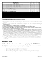
Operating instructions for PWE4 devices
- panel meter for weighing application
- panel meter for standard signals
- free scalable display with setpoints from –999 up to 9999
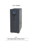
Housing size 96x48
5
1
6
7
0
3
2
P
1
2
3
4
5
6
7
8
4
8
Program key
Minus key
Plus key
Zero key
7-segment display
Setpoint indication 1
Setpoint indication 2
Insertable dimension strip
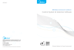
Terminal connection
signal
inputs(DC)
10 11 12 13 14 15
-
+
24V DC
or
115V AC
or
analog
output
(option)
setpoints
230V AC
1
2
S1
3
4
5
6
7
0V
9
0/4-20mA
sensor
supply
(option)
8
COM
-
NC
7
+
NO
6
+
COM
5
-
PWE 4.301....BT
S1
NC
4
NO
3
0V
2
0/4-20mA
10V
1
S2
10V
PWE4.001....B
-
+
+
-
signal
inputs(DC)
sensor
supply
analog
output
(option)
8
9
10 11 12 13 14 15
-
+
24V DC
or
external
tara key
115V AC
or
Schaltpunkt
230V AC
Ordering code
TYP ORDER NUMBER
PWE 4.001.1522B
PWE 4.001.1422B
PWE 4.001.1722B
Power supply 230 VAC
Power supply 115 VAC
Power supply 24 VDC
(galvanic insulated)
terminal connection 15=L
terminal connection 15=L
terminal connection 15=L+
14=N
14=N
14=L–
PWE 4.301.1522BT Power supply 230 VAC
PWE 4.301.1422BT Power supply 115 VAC
PWE 4.301.1722BT Power supply 24 VDC
(galvanic insulated)
terminal connection 15=L
terminal connection 15=L
terminal connection 15=L+
14=N
14=N
14=L–
Options
Green LED
Protection IP54
Protection IP65
Plug in terminal with protection IP40
Plug in terminal with protection IP54
Plug in terminal with protection IP65
PWE411GB.doc
PWE
PWE
4.001....B 4.301....BT
x
x
x
x
x
x
x
x
x
x
x
x
page 1 of 11
Options
Sensor supply 24 VDC/50 mA (for UB 230/115 VAC)
Sensor supply 10 VDC/20 mA (for UB 230/115 VAC)
Sensor supply 24 VDC/50 mA (for UB 24 VDC)
Sensor supply 10 VDC/20 mA (for UB 24 VDC)
The sensor supply is galvanic insulated from the measuring input.
Analog output 0-10 VDC (12 bit)
Analog output 0-20 mA/load 500 Ω
Analog output 4-20 mA/load 500 Ω
Analog output 0-10 VDC – 12 bit (for UB 24 VDC)
Analog output 0-20 mA/load 500 Ω (for UB 24 VDC)
Analog output 4-20 mA/load 500 Ω (for UB 24 VDC)
Dimenion strips on request.
Other power supplies on request.
PWE
4.001....B
Standard
x
Standard
x
PWE
4.301....BT
x
x
x
x
x
x
x
x
x
x
x
x
x
x
x
x
x
x
x
x
Programming (see also programming example)
1. Connect device in line with connection diagram. Connect screen of the sensor line with suitable
potential.
2. Switch on supply voltage. This is followed by a segment test with subsequent switching to
operating mode.
3. Press program key [P]. Program number 0 is displayed.
4. Change program number by simultaneously pressing program key [P] and V key.
5. By pressing the V or W key, the display changes to the value stored under this program number.
6. Change displayed value by pressing the W or V key.
7. With program numbers 1 and 2, the applied voltage (sensor calibration under program number 0
active) can be saved by simultaneously pressing the [P] and W keys. This is confirmed by the
appearance of a horizontal bar in the display. If a different calibration mode (1, 2, 3) is selected, it
is not necessary to apply a voltage to the measuring input. In these modes, all that is needed is to
assign certain display data to the stored restart points (offset and full-scale). The programming is
also carried out under the program numbers 1 and 2 and must be saved with the [P] and W keys.
The appearance of horizontal bars in the display confirms that the save was successful.
8. If no further keys are pressed, the device changes back to operating mode after approx. 7
seconds. This definitively saves all the data, which do not have to be explicitly saved with the P
and W keys.
MIN/MAX data
Additional functions in normal mode for memory inquiry of the MIN/MAX data
The MIN/MAX memory is a volatile memory in which, after switching on the device or since the last
erasure, the relevant minimum and/or maximum values are stored.
•
•
•
By pressing the V key, the MAX memory is displayed.
By pressing the W key, the MIN memory is displayed.
Simultaneously pressing the W and V keys erases the memory stored in the display.
PWE411GB.doc
page 2 of 11
Taring procedure
Operator
Device
Press tare button [0] or external
switch (option)
During the taring procedure, a succession of zeros
appears in the display. The measurement is then
taken over in the display as a "0".
Switching on
Notes, factory settings and error elimination
After the supply voltage is switched on, the device performs a reset including a segment test (all the
LED light up). This is followed by a self-test. Depending on the parameterizing, this may be followed
by an auto-taring process. Should any fault occur during this procedure, the word HELP appears in
the display. This also applies to normal operation. This function serves to protect the surrounding
components and units. If the word HELP appears in the display, a reset must be made to the factory
settings. A reset is performed by switching on the supply voltage with the P key pressed. The display
remains until the P key is released in the segment test, after which the default data are stored. The
unit must now be reprogrammed to the user-specific data.
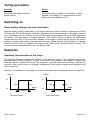
Setpoints
Operating characteristics of the relays
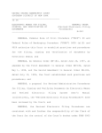
The following diagrams illustrate the behavior of the setpoints (relays). The hysteresis can be programmed freely for each setpoint. In open circuit mode, the respective relay rises on reaching the
threshold, while in closed circuit mode, the respective relay falls when the threshold is reached. By
using the closed circuit mode, for example, a breakdown of the supply voltage can be signaled in the
form of an alarm.
Definition: The hysteresis is the width of the window between the two threshold values of a setpoint!
setpoint
setpoint
on
on
fallen
raised
display
off
hysteresis
Open curcuit mode
PWE411GB.doc
raised
off
fallen
display
hysteresis
Closed curcuit mode
page 3 of 11
Programming lock
Keyboard lock
Possible jumper setting on the back
jumper
1
2
3
terminal
1 2 3
1 2 3
1 2 3
Variation 1
Un-restricted programming. The user has access to all program
numbers.
Variation 2
Programming locked, programming is not possible. The
programming mode is blocked.
Variation 3
Restricted programming. The program numbers 1...6 are blocked
for the user. The program number 61...68 (setpoints) can be
freely configured.
Program table
Function
Program
number
Measuring input
0
Calibration mode
Remark
0 = sensor calibration
1 = 0...10 V
2 = 0...20 mA
3 = 4...20 mA
(Save with P and W)
1
Input of desired indication
Dependent on selected
value for full scale
calibration mode
e.g. 10 V measuring input =
end value 300.0
(Save with P and W)
2
Input of offset for indication Dependent on selected
value
calibration mode
e.g. 4 mA measuring input =
initial value 0.0
(Save with P and W)
3
Setting of decimal point
With V to the desired decimal
point
4
Input of display time
Display time = measuring time
Integrated measuring process
Analog output optional
5
Input of final value for
e.g. 300.0 as in programming
analogue output
example
6
Input of offset for analogue e.g. 0.0 as in programming
output
example
Counter balance
7
Automatic tare while
0 = without automatic tare
switch-on
1 = automatic tare
PWE411GB.doc
Display
Factory
setting
0/1/2/3
0
-999...9999
2000
-999...9999
0
0.1...10.0
seconds
no decimal
point
1,0
-999...9999
2000
-999...9999
0
0/1
0
page 4 of 11
Program
Function
number
Setpoint S1
61
Threshold
62
Hysteresis
63
Closed circuit / open circuit
Setpoint S2
66
Threshold
67
Hysteresis
68
Closed circuit / open circuit
Remark
Display
Factory
setting
Threshold
Width of window between the
two threshold values of a
setpoint.
Working principle
-999...9999
0...9999
500
1
0/1
1
Threshold
Width of window between the
two threshold values of a
setpoint.
Working principle
-999...9999
0...9999
1500
1
0/1
1
Notes on programming
The following programming examples describe the two different tuning methods for setting the
device. A brief explanation will first be given on documenting the display procedure after pressing the
[P] key.
If the keyboard lock is not set (see programming lock), pressing the [P] key will always switch to
programming mode with the program number 0. For approx. 3 seconds, a 0 will appear in the display,
preceded by a P – see programming examples. After 3 seconds, the calibration mode 0 will flash
alternately with the program number 0 for a further 4 seconds By pressing the W or V keys, the
value stored for the calibration mode is displayed for approx. 3 seconds, during which it can be
changed with the W or V keys. After 3 seconds have elapsed, program number 0 flashes alternately
with the currently set calibration mode for a further 4 seconds. The changed value can be saved by
simultaneously pressing the [P] and W keys simultaneously. The device acknowledges this by
displaying 4 horizontal bars. Changing to program number 1 is done by pressing the [P] and V keys.
All further settings can be made by following the above procedure. If you are in programming mode
and do not press any key within 7 seconds, the device automatically reverts from the programming
mode to the operating mode. You can change back again to programming mode at any time by
pressing the [P] key.
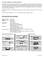
Programming example
1. Sensor calibration / Tuning the measuring section to a real measuring value
When using the sensor calibration, a voltage or current signal must be applied to the display unit for
the scaling. Furthermore, it must be ensured that the device is supplied with the correct auxiliary
voltage. During sensor calibration, the device is tuned to a real measuring value.
The basis for this programming example is the basic values after resetting to the factory settings.
For the sensor calibration, a zero must always be stored under program number 0!
PWE411GB.doc
page 5 of 11
Measuring input:
Measuring signal:
Display:
Display time:
Automatic tare:
Setpoint S1:
Setpoint S2:
Analog output:
0/4...20 mA
4...20 mA
4 mA = 0.0
20 mA = 300.0
2.0 seconds
Automatic tare while switch-on
60.0 and closed circuit
falling at 60.0 and rising at 58.0
(corresponding hysteresis = 2.0)
150.0 and open circuit
Rising at 150.0 and falling at 80.0
(corresponding hysteresis = 70.0)
Measuring signal 4 mA corresponds to a display of 0.0 and 0 V at the analog
output.
Measuring signal 20 mA corresponds to a display of 300.0 and 10 V at the
analog output.
Programming examples
Start of programming
Switch on supply voltage!
Decimal point
Set free scalable value.
To program number 3 with P and
V.
Segment test
Operating mode
Memorize value with P and W.
Take over by display of transversal
bars.
Calibration mode
Enter program mode
Offset
To memorized value with W or V.
Set decimal point.
To program number 2 with P and
V.
Display time
To memorized value with W.
Connect measuring value 4 mA.
To memorized value with W or V.
To program number 4 with P and
V.
Full scale
Connect 20 mA to the measuring
input. To program number 1 with P
and V.
To memorized value with W or V.
Memorize value with P and W.
Take over by display of transversal
bars.
Set display time
To memorized value with W or V.
PWE411GB.doc
page 6 of 11
Analogue output
(optionally)
Final value
Setpoint S1
Setpoint S2
To program number 61 with P and
V.
To program number 66 with P and
V.
To memorized value with W or V.
To memorized value with W or V.
Set free scalable value for setpoint
S1.
Hysterese S2
To program number 5 with P and
V.
To memorized value with W or V.
To program number 67 with P and
V.
Set free scalable final indication
value for analog output.
Hysteresis S1
To program number 62 with P and
V.
To memorized value with W or V.
Offset
To program number 3 with P and
V.
To memorized value with W or V.
To memorized value with W or V.
Set hysteresis for S1.
Set hysteresis for S2.
Working principle S2
To program number 68 with P and
V.
Counterbalance
To program number 7 with P and
V.
Working pinciple S1
To program number 63 with P and
V.
To memorized value with W or V.
To memorized value with W or V.
To memorized value with W or V.
Programming terminated
Set counterbalance (on)
Set open circuit.
PWE411GB.doc
page 7 of 11
2. Factory calibration (standard signals)
When using the factory calibration, there is no need to apply a measuring voltage to the display unit
for scaling. It must be ensured that the device is supplied with the correct auxiliary voltage and that
the correct measuring input is selected. The settings refer to calibration values preset in the factory.
These calibration values are an integral part of the device programming and cannot be erased by
resetting to the factory settings.
The starting basis for this programming example is the basic values following a reset to the factory
settings.
With the factory calibration, a 1, 2 or 3 must be stored under program number 0.
Programming example
Measuring input:
Measuring signal:
Display:
Display time:
Setpoint S1:
Setpoint S2:
Analogue output:
0/4...20 mA
4...20 mA
4 mA = 0.0
20 mA = 300.0
2.0 seconds
60.0 and closed circuit
falling at 60.0 and rising at 58.0
(corresponding hysteresis = 2.0)
150.0 and open circuit
rising at 150.0 and falling at 80.0
(corresponding hysteresis = 70.0)
Measuring signal 0 V corresponds to a display of 0.0 and
0 V at the analogue output
Measuring signal 10 V corresponds to a display of 300.0 and
10 V at the analogue output
Start of programming
Switch on supply voltage
Full scale
To memorized value with W or V.
Select program number 1: Full
scale
Segment test
Operating mode
Calibration mode
Enter program mode
PWE411GB.doc
Select parameter 1 for input
0...10 V.
Memorize value with P and W.
Take over by display of transversal
bars.
To memorized value with W or
V.
Set free scalable value.
page 8 of 11
Memorize value with P and W.
Take over by display of
transversal bars.
Memorize value with P and W.
Take over by display of
transversal bars.
Set decimal point.
The further settings are the same
as in programming example 1.
Offset
Decimal point
Select program number 2: Offset
Select program number 3:
Decimal point.
To memorized value with W or
V.
Proceed to the section on display
time.
To memorized value withW or V.
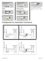
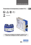
L+
LSensor supply
+
+
L+
Transmitter
Sensor supply
L+
Transmitter
Supply voltage
24VDC
+
+
Transmitter
L
Supply voltage
24VDC
+
Transmitter
L-
PWE411GB.doc
N
Input 0/4...20mA
L
Input 0...10V
Com 0V
Input 0/4...20mA
N
-
Supply voltage
230VAC
115VAC
Com 0V
-
Com 0V
Input 0/4...20mA
Supply voltage
230VAC
115VAC
Input 0...10V
Com 0V
Input 0/4...20mA
Configuration for transmitter connections
L+
L-
L+
page 9 of 11
-
+
+
Transmitter
Sensor supply plus
Sensor supply minus
Com 0V
Input 0/4...20mA
Supply vopltage
230VAC
115VAC
24VDC
Input 0...10V
Sensor supply plus
Sensor supply minus
Com 0V
Input 0/4...20mA
Configuration for transmitter connections
Supply voltage
230VAC
115VAC
24VDC
+
Transmitter
Technical data
Dimensions
Housing
Assembly cut out
Fixing
Housing material
Protective system
Weight
Connection
Input
Measuring range
Input resistance
96x48
Output
Sensor supply
Relay output
Analogue output
96 x 48 x 134 mm, incl. screw terminal
92.0+0.8 x 45.0+0.6 mm
snap-in, quick-fix system with plastic clips for wall
thicknesses up to 50 mm
PC/ABS blend, colour black, UL94V-0
front IP40, connection IP00
approx. 450 g
on the back with terminals up to 2.5 mm2
0-10 V, 0-20 mA, 4-20 mA
The maximum permitted value on the input clips is
is 120% of the nominal value.
All ranges can be selected via connecting clip.
Ri with
10 V = 55 kΩ, 20 mA = 100 Ω
Sensor supplies are galvanic insulated!
24 VDC/50 mA, 10 VDC/20 mA
(other power supplies on request)
load 230 VAC/5 A – 30 VDC/2 A
0-10 VDC (12 bit)
galvanic insulated!
0-20 mA (12 bit) - load 500 Ohm
galvanic insulated!
4-20 mA (12 bit) - load 500 Ohm
galvanic insulated!
Accuracy
Resolution
Measuring fault
Temp. coeff.
Measuring principle
-999 up to 9999
+/-0.2% of measuring range, +/- 1 digit
100 ppm/K
voltage/frequency converter
Mains unit
Power supply
230/115 VAC +/- 10% (50-60 Hz)
24 VDC +/-10% galvanic insulated
approx. 5 VA
Power consumption
PWE411GB.doc
page 10 of 11
Indication
Ambient
conditions
Display
Overflow
Display time
7-segments-LED, 14 mm, red
4-digit = indication 9999 digit
indication of 4 transversal bars
adjustable from 0.1....10.0 seconds
Working temperature
Storing temperature
0... + 60 {C
-20... + 80 {C
CE symbol
For unrestricted use of the device in accordance with the guideline on electromagnetic
compatibility 89/336/EWG, analogue input lines must be screened off. The screen must be
places on one side as close to the device as possible.
Housing:
90
48
43
111
96
5
PWE411GB.doc
th
(wi
8)
l 14
1 ina
13 term
g in
plu
page 11 of 11