1
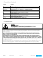
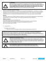
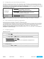
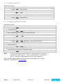
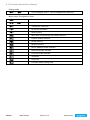
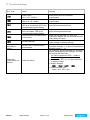
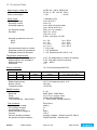
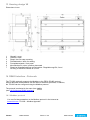
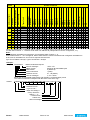
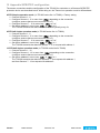
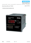
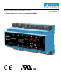
Temperature Relays and MINIKA®, Mains Monitoring, Digital Panelmeters MINIPAN®, Switching Relays and Controls Operating Instructions TR1200 ZIEHL industrie – elektronik GmbH + Co KG Daimlerstraße 13, D – 74523 Schwäbisch Hall + 49 791 504-0, [email protected], www.ziehl.de updated: 130215 Ba/Fz from Firmware: -02 - Pt 100 thermostat with 12 sensor ports and Interface RS485 TR1200 12320-0702-03 Page 1 / 20 www.ziehl.de Table of contents 1 Application and brief description .......................................................................................................... 3 2 Overview of functions ............................................................................................................................ 3 3 Display and controls .............................................................................................................................. 4 4 Description of terminals ......................................................................................................................... 5 5 Important Notes ...................................................................................................................................... 5 6 Installation .............................................................................................................................................. 6 7 Connection diagram ............................................................................................................................... 7 8 Commissioning....................................................................................................................................... 7 9 8.1 Control chart .................................................................................................................................. 7 8.2 Description of the parameters ........................................................................................................ 8 8.3 Display mode (last decimal point off) ............................................................................................. 8 8.4 Menu mode (last decimal point on) ................................................................................................ 8 8.5 Configuration mode (last decimal point flashes) ............................................................................. 9 8.6 2-wire technique line resistance compensation .............................................................................. 9 8.7 Configuring sensors ....................................................................................................................... 9 8.8 Configuring the relay.................................................................................................................... 10 8.9 Configuring the RS485 interface .................................................................................................. 10 8.10 Simulation .................................................................................................................................... 11 8.11 Code lock .................................................................................................................................... 11 8.12 Possible indications in display...................................................................................................... 12 Factory settings and software version ............................................................................................... 13 10 Maintenance and repair........................................................................................................................ 13 11 Trouble shooting .................................................................................................................................. 14 12 Technical Data ...................................................................................................................................... 15 13 Housing design V8 ............................................................................................................................... 17 14 RS485 interface - Protocols ................................................................................................................. 17 14.1 Modbus protocol .......................................................................................................................... 17 14.2 RS485 Protocol ........................................................................................................................... 18 15 Appendix SIPROTEC configuration .................................................................................................... 20 TR1200 12320-0702-03 Seite 2 / 20 www.ziehl.de 1 Application and brief description The Pt 100 thermostat TR1200 is especially suitable for temperature monitoring wherever up to 12 different measuring points must be monitored simultaneously: Motors and generators, Simultaneous monitoring of bearings and coolant Transformers with additional monitoring of the core temperature power machines and plants The Pt 100 thermostat TR1200 measure the temperature of up to 12 Pt 100 thermometers. With the RS485 Interface measured temperature values can be issued i.e. for remote control or further evaluation. One error relay monitors sensor failures und signals general malfunctions. 2 Overview of functions TR1200 3-digit temperature display 12 inputs for temperature sensors, 1…12 sensors can be connected Pt 100 thermostats with 2- or 3- wire connection 1 Error relay (potential-free change-over contact) RS485 Interface (ZIEHL standard protocol and Modbus RTU protocol) LED signal the measuring channel, Error state, relay function and RS485 activity Code lock prevents parameter manipulation TR600 compatible (to replace one TR600 with 6 sensors connected) Universal power-supply AC/DC 24-240 V Snap mounting on 35 mm standard rail EN 60715 12320-0702-03 Seite 3 / 20 www.ziehl.de 3 Display and controls 1 LED relay state (yellow) OFF The relay is released Illuminated The relay is picked up 2 LED sensors (yellow) Illuminated Displays the sensor value belonging to the LED in the digital display flashes, 8Er18or8Er28 Sensor error in the corresponding sensor circuit All illuminated Displays the value of the warmest sensor in the digital display 3 Digital display 3 digits (red) Display of sensor value Display of error codes e.g. 8Er98 4 Hindmost decimal point (red) OFF Display mode Illuminated Menu mode flashes Parameter mode 5 LED error (red) OFF Illuminated with 8Er18 , 8Er28 , 8Er88 or 8Er98 normal operation Sensor error, malfunction, invalid parameter 6 Button Up / Down (display mode, normal operation) Press briefly Change into the menu mode (see Operating instructions Point 8.4) Displays the stored MAX value (Up) / MIN value(Down) – press also Press for > 2s button Set for ≥ 2s to erase the stored value 7 Button Set / Reset (display mode, normal operation) Press briefly Displays the value of next sensor (sensor LED illuminates) Press for > 2s Reset, back to display mode Displays the software version (e.g. 000) Press for > 10s 8 TR1200 LED RS485 Interface (yellow) Rx flashes briefly Unit is receiving data via the RS485 interface Tx flashes briefly Unit is transmitting data via the RS485 interface 12320-0702-03 Seite 4 / 20 www.ziehl.de 4 Description of terminals Terminal Function A1 and A2 Supply Voltage Us, see Operating Instructions Point 12 11, 12, 14 Error relay change-over contacts 1T1…12T3 Sensor connection (xT2 = Sense line of three wire technique) A RS485 receiving wire A´ RS485 load resistor, jumper to terminal A required B RS485 transmitting wire B´ RS485 load resistor, jumper to terminal B required (Gnd) Ground wire of RS485 interface, potential equalisation between multiple units 5 Important Notes DANGER! Hazardous voltage! Will cause death or serious injury. Turn off and lock out all power supplying this device before working on this device. To use the equipment flawless and safe, transport and store properly, install and start professionally and operate as directed. Only let persons work with the equipment who are familiar with installation, start and use and who have appropriate qualification corresponding to their function. They must observe the contents of the instructions manual, the information which are written on the equipment and the relevant security instructions for the setting up and the use of electrical units. The equipments are built according to DIN / EN and checked and leave the plant according to security in perfect condition. To keep this condition, observe the security instructions with the headline „Attention“ written in the instructions manual. Ignoring of the security instructions may lead to death, physical injury or damage of the equipment itself and of other apparatus and equipment. If, in any case the information in the instructions manual is not sufficient, please contact our company or the responsible representative. Instead of the industrial norms and regulations written in this instructions manual valid for Europe, you must observe out of their geographical scope the valid and relevant regulations of the corresponding country. TR1200 12320-0702-03 Seite 5 / 20 www.ziehl.de ! ATTENTION! When all relays are programmed in operation current mode (= pick up at alarm), a loss of the supply voltage or an instrument failure can remain unidentified. When the relay is applied as control instrument, the operator must ensure, that this error is recognized by regular examinations. We recommend to program and accordingly evaluate at least one relay in the closed-circuit current mode. Caution! Temperature sensor terminals The pin connections of Sensors 1…6 (below) are not compatible with Sensors 7…12 (above). If a 3-wiretechnique sensor connected below is to be connected above, both external connections must be swapped. Temperature sensors must be connected to the plug-in terminals T11, T12, T13 etc. To ensure proper operation this plug-in terminals have gold-plated contacts. Do not use these plugs for other terminals. Caution! The sensor inputs and the RS485 interface are applied to the same electrical potential but are galvanically isolated (2kV) for the auxiliary voltage. Take this into consideration during configuration. RS485 connection: Use RS485 Interface only with shielded wires. Large cable lengths may shift the potential ground and the transmission can be disturbed. Corrective measures can be galvanic separation or an additional ground wire. Max. allowed cable length is 1000m. 6 Installation The device can be mounted: Distribution board or switchgear cabinet on 35 mm rails according to EN 60715 Observe the maximum temperature permissible when installing in switching cabinet. Make sure sufficient space to other equipment or heat sources. If the cooling becomes more difficult e.g. through close proximity of apparatus with elevated surface temperature or hindrance of the cooling air, the tolerable environmental temperature is diminishing. ! Attention! Universal power supply The unit is equipped with a universal power supply that is suitable for DC- and ACvoltages. Before connecting the unit to the current, make sure that the allowed scope of voltage of the control voltage Us, written on the lateral type plate, corresponds to the supply voltage of the unit. ! A circuit-breaker or switch must be situated within easy reach of the unit and fused. Installation excess current protection should be ≤ 10 A. TR1200 12320-0702-03 Seite 6 / 20 www.ziehl.de 7 Connection diagram 8 Commissioning 8.1 Control chart Display mode >2s = max = Up = Set = Reset >2s ... Sensor 1 Sensor 1-12 Max Sensor 12 ... ... >2s = Down = min Parameter mode S 1 Menu mode Sen. rel rel. 0...99.9 3-L nc Prt Si Si . 0...99.9 3-L nc bdr [baud] 48/ 96/ 192 ... r …A Adr bus. S12 Mod -------485 Adr Sensor S 1 … S12 0 ...96 1 ...247 pin TR1200 000 ...999 12320-0702-03 On/ off [ ] = unit Code-Reset = press 2 s Set when switching on supply voltage. (Pin = 504) 3X on/off Cod Eve/ Odd/ no Up/Down together resets values to Zero. [°C] -199 ...850 3X err Cod. par alternating Display pin Seite 7 / 20 000 ...999 Error Code: -EE = under range EEE = over range Er1 = short circuit sensor Er2 = interruption sensor Er8 = Internal device error Er9 = invalide parameter www.ziehl.de 8.2 Description of the parameters Parameters 8.3 Display Explanation Adjustment range Sensors 8Sen.8 Menu item for sensor configuration 8S 18 … 8S128 Sensor 8S 18 8S 28 ... Sensor configuration (line compensation) S1…S12 80.008 , 83-L8 , 8 nc8 Relay function 8rel8 Zero signal current / operating current 8 Bus 8bus.8 Protocol 8Prt8 Set ZIEHL / Modbus protocol 8 8 08 … 8 968 18 … 82478 Address 8Adr8 Set the device address 8 8 08 … 8 968 18 … 82478 Baud rate 8bdr8 Set the baud rate Parity 8par8 Set the parity bit Menu item for configuring the RS485 interface r8 , 8 A8 84858 , 8Mod8 8 488 8 968 81928 8eve8 8odd8 8 no8 = 4800 = 9600 = 19200 = even = odd = none Display mode (last decimal point off) In the display mode, the TR1200 is in its normal state; here the temperature of the selected sensor is displayed. In addition, the error codes (e.g. 8er18) are also displayed. Function key Set / Reset Press briefly: Switches the sensor over Press for > 10 s: Displays the software version (e.g. 80008 Press briefly: Changes into the menu mode Function key Up / Down 8.4 Press for ≥2 s: Displays MAX and MIN measurements, additionally pressing the Set key for ≥ 2s deletes the saved values Menu mode (last decimal point on) The menu mode is used to select the menu items. If no key is pressed for 30s, one automatically returns to the display mode. Function key Set / Reset Function key Up / Down TR1200 Press briefly: Changes into the configuration mode Press for ≥2 s: Returns to the display mode (the most recently set values are then taken over) Press briefly: Select menu item; switches to the display mode 12320-0702-03 Seite 8 / 20 www.ziehl.de 8.5 Configuration mode (last decimal point flashes) The value of a parameter can be set in the configuration mode. The display continually alternates between the parameter name and the currently set value until the Up/Down key is pressed, which changes the value of the parameter. If no key is pressed for 2s, the display starts alternating. If no key is pressed for 30s (simulation mode 15min), one automatically returns to the display mode (the most recently set value is taken over) Press briefly: The settings are taken over; continue to next parameter. After the last parameter, change into menu mode Function key Press for ≥2 s: Returns to display mode (except Set / Reset simulation mode), the most recently set values are taken over during this Function key Press short/long: Changes the parameter value Up / Down (fast/slow) Hint: Pressing the Up and Down keys simultaneously sets the adjustable value to zero. If you keep the Up or Down key pressed while setting a value, the speed of the change in the display is accelerated. 8.6 2-wire technique line resistance compensation Connect the sensor at terminals xT1 and xT3, xT2 has to be open. To compensate the line resistance short-circuit the wires nearby the sensor and measure the line resistance. We recommend using 2 or bettering 3 wires for each sensor. With 2-wire connection and a common line for all signals, all sensor measuring currents will be added on the common line. Thus the value of the compensation line resistance RK must be calculated as follows: RK = (n+1) x RL/2 (RL = line resistance of two wires, n = number of sensors) 8.7 Configuring sensors Adjustment process: Select the menu item with the Up/Down key until … Display 8SEN.8 Press the Set key Display 8S 1 8 / 83-L8 (Sensor 1 / Connection type) flash alternately Use the Up and Down keys to set the connection type or line resistance. Sensor not connected: Select 8 nc8 3-conductor connection: Select 83-L8 2-conductor connection: 80.008 Perform a line compensation and adjust the line resistance Press the Set key Display 8S 2 8 / 83-L8 (Sensor 2 / Connection type) flash alternately Configure all 12 sensors in this manner. TR1200 12320-0702-03 Seite 9 / 20 www.ziehl.de 8.8 Configuring the relay Adjustment process: Select the menu item with the Up/Down key until … Display 8rel.8 (Relay function) Press the Set key Display 8rel8 / 8 r8 (Relay function / Zero signal current) flash alternately Use the Up and Down keys to select the relay function Press the Set key (exits the configuration mode) Display 8rel.8 (Relay function) 8.9 Configuring the RS485 interface Adjustment process: Select the menu item with the Up/Down key until … Display 8bus.8 (Bus) Press the Set key Display 8prt8 / 84858 (Protocol / 485) flash alternately Set the desired protocol using the Up and Down keys Press the Set key Display 8adr8 / 8 08 (Device address / Value) flash alternately Set the desired device address using the Up and Down keys Press the Set key Display 8bdr8 / 8 968 (Baud rate / Value) flash alternately Set the desired baud rate using the Up and Down keys Press the Set key Display 8par8 / 8eve8 (Parity / Value) flash alternately Set the desired parity bit using the Up and Down keys Press the Set key (exits the configuration mode) Display 8bus.8 (Bus) Note: The set device address always applies for the transmission of Sensors 1…6. If at least one of the sensors 7…12 as is configured as 2- or 3-conductor (not „nc“), they will be transmitted with the set device address+1. More information about Modbus configuration and programming can be found in Appendix 1 (Download from www.ziehl.com) TR1200 12320-0702-03 Seite 10 / 20 www.ziehl.de 8.10 Simulation A sensor can be selected and a temperature simulated here. All device functions operate as if this value is actually being measured. Error messages are only indicated by LED and not in the display. The set values are simulated until the menu item 8si .8 is left with the Up or Down button. If no key has been pressed for 15 minutes, the device automatically switches back to the display mode. Adjustment process: Select the menu item with the Up/Down key until … Display 8si .8 (Simulation) Press the Set key Display 8si 8 / 8S 18 (Simulation / Sensor) flash alternately Use the Up and Down keys to select the sensor function Press the Set key Display 8 08 (Temperature) Simulate the desired temperature using the Up and Down keys Press the Set key Display 8si .8 (Simulation) By pressing the Set button repeatedly all sensors can be selected in succession. The simulated values are retained until the menu item 8si .8 is left by pressing Up or Down. 8.11 Code lock Here, the set parameters can be protected by activating a code lock. The device acknowledges an incorrect entry with 8err8 (flashes three times). Adjustment process: Select the menu item with the Up/Down key until … Display 8Cod.8 (Code lock) Press the Set key Display 8Pin8 / 8 08 (Pin / Pin code) flash alternately Use the Up and Down keys to set the saved pin code (factory setting is 85048 ) Press the Set key Set the desired code block using the Up and Down keys: o 8off.8 off, all parameters can be changed o 8 On8 on, no parameters can be changed Press the Set key Display 8Pin8 / 8 5048 (Pin / Pin code) flash alternately Set the desired new pin code with the Up and Down keys (caution: write down the pin code) Press the Set key (exits code locking) Code lock on, display 8 on8 flashes three times Code lock off, display 8off 8 flashes three times Display 8Cod.8 (Code lock) TR1200 12320-0702-03 Seite 11 / 20 www.ziehl.de 8.12 Possible indications in display Display mode 8Er18 … 8er98 Error messages (see 11. Error messages and measures) Menu mode / Configuration mode 8Sen.8 Menu item sensor configuration 8S 18 … 8S128 Sensors 1…12 83-L8 3-conductor connection 8 nc8 No sensor connected 8rel8 Relay function 8bus.8 Menu item for configuring the RS485 interface 8Prt.8 Protocol RS485 interface 84858 RS485 protocol 8Mod8 Modbus protocol 8adr8 Device address RS485 interface 8bdr8 Baud rate RS485 interface 8par8 Parity bit RS485 interface 8Si 8 Simulation 8Cod8 Code lock 8Pin8 Pin code (factory setting 504) TR1200 12320-0702-03 Seite 12 / 20 www.ziehl.de 9 Factory settings and software version Press button "SET" for 10 s when switching on supply voltage for factory settings. Menu mode Sen. rel. Bus. Si Code Parameter Factory settings 8S 18 (Sensor 1) 83-L8 8S 28 (Sensor 2) 83-L8 8S 38 (Sensor 3) 83-L8 8S 48 (Sensor 4) 83-L8 8S 58 (Sensor 5) 83-L8 8S 68 (Sensor 6) 83-L8 8S 78 (Sensor 7) 8 nc8 8S 88 (Sensor 8) 8 nc8 8S 98 (Sensor 9) 8 nc8 8S108 (Sensor 10) 8 nc8 8S118 (Sensor 11) 8 nc8 8S128 (Sensor 12) 8 nc8 8rel8 (Relay function) 8 8prt8 (Protocol) 84858 8adr8 (Unit address) 8 8bdr8 (Baud rate) 8 968 8par8 (Parity bit) 8eve8 8S 18 (Sensor 1) 88508 My configurations r8 08 … 8S128 (Sensor 12) 88508 8 On8 / 8off8 8off8 8pin8 (PIN code) 85048 Display of Software-Version: Press "SET" for 10 s in display mode. 10 Maintenance and repair The devices are maintenance-free. Only the manufacturer may accomplish repairs. We recommend an examination within the regular maintenance periods of the plant, in which the equipment is installed. TR1200 12320-0702-03 Seite 13 / 20 www.ziehl.de 11 Trouble shooting Error code Cause Remedy 8-EE8 Under range 15 Ω < R < 18,39 Ω check sensor and line resistance compensation Over range 390,26 Ω < R < 400 Ω Sensor or line short circuit LED error illuminates, LED of the corresponding sensor flashes Sensor or line interruption LED error illuminates, LED of the corresponding sensor flashes check sensor and line resistance compensation 8EEE8 8Er18 8Er28 8Er88 Internal device error Malfunction of the device 8Er98 Invalid parameter Wrong temperature values Sensors with 3-wire technique interchanged Parameter configuration not allowed Code lock active TR1200 12320-0702-03 check sensors/wires/terminals check sensors/wires/terminals Switch unit off and back on. If the error continues to appear, the unit must be returned to the factory for repair. Press button "SET" for 10 s when switching on supply voltage for factory settings. Check sensors with 3-wire technique. Terminals of sensor 1…6 are not compatible to terminals sensor 7…12 The Code-lock can be activated as a protection against manipulation of the settings. The user can change the PIN-Code. You have forgotten the PIN? -> Make a code-reset: press button "SET" for 2 s when switching on supply voltage display changes 88888 – 8Cod8 – 8off8 – 88888 Release button „SET“ Code = OFF, PIN = 504 Seite 14 / 20 www.ziehl.de 12 Technical Data Rated supply voltage Us: Tolerance Power consumption AC/DC 24 – 240 V, 0/50/60 Hz DC 20, 4 - 297 V AC 20 - 264 V <3W < 10 VA Relay output: Switching voltage Switching current Switching capacity 1 Wechsler (CO) max. AC 415 V max. 5 A max. 1250 VA (ohmic load) max. 120 W at DC 24 V 250 V ac, 5 A, resistive 240 V ac, 1/2 hp 120 V ac, ¼ hp B 300 – pilot duty, UL 508 UL electrical ratings: E214025 Nominal operational current Ie: AC15 DC13 Recommended fuses for contact Expected contact life mechanical Expected contact life electrical Ie = 3 A Ue = 250 V Ie = 2 A Ue = 24 V Ie = 0,2 A Ue = 125 V Ie = 0,1 A Ue = 250 V T 3,15 A (gL) 1 x 10⁷ operations 1 x 10⁵ operations at AC 250 V / 6 A Temperature measurement: Measuring time sensor resistance Measuring time line resistance Measuring range Resolution 0,25…3s (depending on number of sensors) 0,25…30s (each cycle of a sensor) -199°…850°C 1°C Sensor connection: 12 x Pt 100 according EN 60751 Sensor Pt 100 temperature range °C min max -199 860 Short circuit (Ohm) < 15 Measuring accuracy Sensor current Temperature drift RS485 interface Address of unit Baud rate Parity Cable length Time end request – start answer Test conditions Rated impulse voltage Overvoltage category Contamination level Rated insulation voltage Ui On-time Galvanic isolation between No galvanic isolation between TR1200 12320-0702-03 Interruption (Ohm) > 400 Pt 100 + RL (Ohm) max 500 ±0,5 % of measuring value ±1 K ≤0,8 mA <0,04°C/K 0…96 4800, 9600, 19200 Baud N, O, E (no, uneven, even) 1000m with 19200 Baud 6…10ms (ZIEHL RS485 protocol) EN 61010-1 4000 V III 2 300 V 100 % auxiliary voltages – Sensor ports DC 3820 V RS485 interface – Sensor ports Seite 15 / 20 www.ziehl.de EMC-tests Emitted interference Burst SURGE Discharge of static electricity Environmental conditions Ambient temperature range Storage temperature range Altitude Climatic conditions External wiring temperature range Vibration resistance EN 60068-2-6 Housing Dimensions (W x H x D) Mounting height/width Wire connection, single wire Stranded wire with insulated ferrules Torque of screw Protection class housing / terminals Fitting position Installation Weight EN 61326-1 EN 61000-6-3 EN 61000-4-4 +/-4 kV Pulse 5/50 ns, f = 5 kHz, t = 15 ms, T = 300 ms IEC 61000-4-5 +/-4 kV Impulse 1,2/50 µs (8/20 µs) IEC 61000-4-2 +/-4 kV contact, +/- 8kV air -20 °C ... +65 °C -20 °C … +70 °C Up to 2000 m 5 – 85 % rel. humidity, no condensation -5 °C … +70 °C 2…25 Hz ±1,6 mm 25 ... 150 Hz 5 g Design V8, distribution cabinet mounting 140 x 90 x 58 mm 55 mm / 8 TE each 1 x 1.5 mm2 each 1 x 1,0 mm2 0,5 Nm (3,6 lb.in) IP 30 / IP 20 any Snap mounting on mounting rail 35 mm according to EN 60715 or with screws M 4 (additional bar in scope of delivery) app. 350 g Subject to technical changes TR1200 12320-0702-03 Seite 16 / 20 www.ziehl.de 13 Housing design V8 Dimensions in mm 1 2 3 4 5 6 7 Oberteil / cover Unterteil / base Riegel / bar for snap mounting Plombenlasche / latch for sealing Frontplatteneinsatz / front panel Kennzeichen für unten / position downward Riegel bei Wandbefestigung mit Schrauben. Riegelbohrung Ø 4,2 mm / for fixing to wall with screws, Ø 4,2 mm. 14 RS485 interface - Protocols The TR1200 optionally supports the Modbus or the ZIEHL RS485 protocol. Device data and measurements can be read out with both protocols; in addition, the TR1200 can be configured using the Modbus protocol. The protocol is selected in the menu item 8bus.8. (see 8.9 Configuring RS485 interface) 14.1 Modbus protocol You can find documentation on the Modbus protocol in the Internet at www.ziehl.com TR1200 – Modbus Appendix TR1200 12320-0702-03 Seite 17 / 20 www.ziehl.de 14.2 RS485 Protocol Depending on the configured data mode the TR1200 transmits data with ZIEHL TR600 protocol in data mode 0 or with TR1200 protocol in data mode 4. Transmission format: Compatibility: Baud rate: Data bits: Stop bit: Parity: Separated by: ASCII TR600 RS485 (Modus 0) 9600 (default), 4800, 19200 8 1 even (default), odd, no ";" (ASCII) Master requests data from TR1200: Master sends <start><address of unit><read-command><data mode><BCC><CR><LF Start of message: Address of unit Read command: Data mode: Block check (BCC): Carriage Return (CR): Line Feed (LF): s (ASCII) or S (ASCII) or STX (0x02) 0…99 (ASCII) r (ASCII) or R (ASCII) 0…9 (ASCII) EXOR of all transmitted bytes 0x0D 0x0A 1 2 1 1 3 1 1 10 Byte Byte Byte Byte Byte Byte Byte Byte TR1200 sends the requested data: TR sends: <start><type of unit><address of unit><mode><data> <BCC><CR><LF> Start of message: Type of unit: Address of unit:: Data mode: Value sensor 1 (7): Value sensor 2 (8): Value sensor 3 (9): Value sensor 4 (10): Value sensor 5 (11): Value sensor 6 (12): Alarm 1: Alarm 2: Alarm 3: Alarm 4: Alarm 5: Alarm 6: Alarm 7: Internal error: Block check (BCC): Carriage Return (CR): Line Feed (LF): s (ASCII) or S (ASCII) or STX (0x02) (same as request) TR600 (ASCII) or TR120 (ASCII) 0…99 (ASCII) 0…9 (ASCII) * -199…+850 (ASCII) * -199…+850 (ASCII) * -199…+850 (ASCII) * -199…+850 (ASCII) * -199…+850 (ASCII) * -199…+850 (ASCII) 0 (ASCII) 0 (ASCII) 0 (ASCII) 0 (ASCII) 0 (ASCII) 0 (ASCII) 0..1 (ASCII) *² 0…99 (ASCII) EXOR of all transmitted bytes 0x0D 0x0A 1 Byte 5 2 1 4 4 4 4 4 4 1 1 1 1 1 1 1 2 3 1 1 64 Byte Byte Byte Byte Byte Byte Byte Byte Byte Byte Byte Byte Byte Byte Byte Byte Byte Byte Byte Byte Byte * Sensor not connected, data "+980" Sensor short circuit, data "-999" Sensor interruption, data "+999" *² 01=EEprom error, 02=parameter error, 03=ADC error TR1200 12320-0702-03 Seite 18 / 20 www.ziehl.de + + + + + + + + + + + + + + + + + ";" ";" ";" ";" ";" ";" ";" ";" ";" ";" ";" ";" ";" ";" ";" ";" ";" x x LF x CR x Block check x Internal error x Alarm 7 x x x x x x Alarm 6 x x x x x x Alarm 5 x x x x x x Alarm 4 x x x x x x Alarm 3 x x x x x x Alarm 2 x x x x x x Alarm 1 x x x Sensor 12 x x x Sensor 11 x x x Sensor 10 x x x Sensor 9 x x x Sensor 8 Sensor 6 x x x Sensor 7 Sensor 5 x x x x x x x Sensor 4 x x x x x x x Sensor 3 TR600 TR600 TR120 TR600 TR120 TR600 TR120 Sensor 2 x x x x x x x Sensor 1 Data mode 3 Unit number 2 Type of unit 1 0 3s 0 x 4 x 0 x 4 x 0 x 4 x Start of message 0 Answer of TR unit Request/Transmission Data mode Address of unit Para meter 0 0 0 0 0 0 0 0 0 0 0 0 0 0 0 0 0 0 0 0 0 0 0 0 x x x x x x x x x x x x x x x x x x x x x x x x x x x x x x x x x x x . . . 94 x 3s x TR600 x x x x x x x x 0 0 0 0 0 0 x x x x 95* x 3s x TR600 x x x x x x x x 0 0 0 0 0 0 x x x x 96 x 3s x TR120 x x x x x x x x x x x x x x x x x x *when unit address 94 is configured, data of sensor 1…6 will be send in 3s under unit address 94 and 3s later data of sensor 7…12 will be send under unit address 95 (independent of sensor configuration „nc“). Hints: The configured unit address is permanent for transmitting data of sensor 1...6. If one of the sensors 7…12 is configured, data of these sensors will be transmitted with configured unit address+1. In the case of unit address 0, 94 und 96 no request must be send. Type of unit TR600 = 64 Byte, Type of unitTR120 = 82 Byte Example: Request: s01r0048\r\n Master sends data request <End of message> <CR> <LF> <Block check> EXOR of all transmitted bytes <data mode> 0 (Modus 0) <Read command> r (read) <Address of unit> 01…99 (ASCII) <start of message> s, S or <STX> Block sum: s(115) EXOR 0(48) EXOR 1(49) EXOR r(114) EXOR 0(48) = 048 The values in brackets correspond with the ASCII-code of the sign. Answer: sTR600;01;0;+154;-055;+268;+999;+980;-999;1;0;0;1;0;0;1;02;119\r\n <Data mode> <Address of unit> < Type of unit > < Start of message > <Temp. Sensors> <Alarm 1…7> < Internal error > < Block sum > <End of message> TR1200 12320-0702-03 Seite 19 / 20 www.ziehl.de x x x 15 Appendix SIPROTEC configuration The sensor connections and the configuration of the TR1200 for evaluation on a Siemens SIPROTEC protection device are described below. While doing so, the Thermo box operation mode is differentiated. 6 RTD Simplex operation mode (1x TR1200 works like 1x TR600) = Factory setting Connect Sensors 1…6 Configure Sensors 1...6 in menu item 8SEN.8 depending on the connection (configure sensors that are not connected as "nc") Configure Sensors 7…12 in menu item 8SEN.8 as "nc" Set device address in menu item 8bus.8 8adr8 to 0 The TR1200 transmits the data from Sensors 1...6 cyclically every 3s. 6 RTD half duplex operation mode(1x TR1200 works like 1x TR600) Connect Sensors 1…6 Configure Sensors 1...6 in menu item 8SEN.8 depending on the connection (configure sensors that are not connected as "nc") Configure Sensors 7…12 in menu item 8SEN.8 as "nc" Set device address in menu item 8bus.8 8adr8 to 1 The TR1200 transmits the data from Sensor 1…6 on request with address 1. 12 RTD half duplex operation mode (1x TR1200 works like 2x TR600) Connect Sensors 1…12 Configure Sensors 1...12 in menu item 8SEN.8 depending on the connection (configure sensors that are not connected as "nc") Set device address in menu item 8bus.8 8adr8 to 1 The TR1200 transmits the data from Sensors 1...6 on request with address 1, and from Sensors 7...12 on request with address 2. TR1200 12320-0702-03 Seite 20 / 20 www.ziehl.de