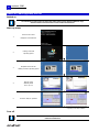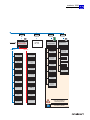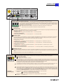
1
V1.4
2
andronic 2060
Operating Instructions
Version V 1.4
Date 07.04.2011
Author Pa/Scho
Editing/Illustrations Pa
Filename operating_instructions_andronic_2060 _v1_4.doc
Trademark All product names or trademarks are properties of their respective owners.
Copyright © andron GmbH 2011. All Rights Reserved.
Copying this document, giving it to others and the use or communication of the contents thereof
without express authority, are forbidden. Offenders are liable for the payment of damages. All rights
are reserved in the event of the grant of a patent or the registration of a utility model or design.
Validity There could be additional functions running in the control who are not mentioned in this
documentation. It insists no claim for this functions, in case of a new delivery or a service case.
All rights are reserved with respect to the content of this documentation and the availability to the
product.
Published by andron GmbH, Schlätterstraße 2, 88142 Wasserburg, Germany
Telephone +49 (0) 8382/9855-0, Fax +49 (0) 8382/9855-50
e-Mail: [email protected]
www.andron.de
andronic 2060
Operating Instructions
3
Table of contents
Table of contents .................................................................. 3
Revisions .............................................................................. 3
Notice .................................................................................. 4
Safety notes ......................................................................... 4
Warning notes and symbols............................................ 4
Use as directed .............................................................. 5
Introduction ........................................................... 5
Field of applications ................................................ 5
Not used as directed ...................................................... 5
Switch on, start-up phase, turn off......................................... 6
Switch on ...................................................................... 6
Start-up phase............................................................... 6
Turn off......................................................................... 6
Switch off / Shut down................................................... 7
Operating system setting, system additionals, user profiles...... 8
Coordinate systems, zero points, reference points................... 9
Machine zero point unequal control zero point ................. 9
Machine zero point equal control zero point..................... 9
Menu overview ................................................................... 10
Operating panel keys .......................................................... 12
The Info system.................................................................. 15
Change database ......................................................... 15
Error list ...................................................................... 15
System information ...................................................... 15
Start application program ............................................. 15
System messages ........................................................ 15
Configuration............................................................... 15
NC Mode ............................................................................ 16
Create/modify NC program (EDIT) ................................ 16
G&M editor........................................................... 16
Position display (POSIT) ............................................... 16
RESTART.............................................................. 16
INPUT .................................................................. 17
TOOL ................................................................... 17
POS-CHG.............................................................. 17
G&M-DIS.............................................................. 17
MDI ..................................................................... 17
PRESET ................................................................ 17
Program specific configuration (PRCON) ........................ 17
Program directory (DIR) ............................................... 17
Delete program (DELETE)............................................. 17
Zero point offset (0-OFFS)............................................ 18
PASSW ................................................................. 18
Teach .......................................................................... 18
Load automatic program (AUTOM) ................................ 18
DNC function (DNC) ..................................................... 18
G&M-CNV ............................................................. 18
Tool management ............................................................... 19
Overview of functions ................................................... 19
Activation of the tool management (TOOL) .................... 19
Select magazine assignment table (TL-SEL) ................... 19
Edit magazine assignment table (TT-EDIT) .................... 20
DEFPAGE F2 ......................................................... 20
Edit tool data (TL-EDIT)................................................ 21
Optional parameter ............................................... 21
Tool dimensions .................................................... 21
Tool life acquisition................................................ 22
Additional correction values ................................... 22
Special functions ................................................... 22
Delete magazine assignment table (TT-DEL) .................. 22
Delete tool file (TL-DEL) ............................................... 22
Search tool (TL-SEAR) .................................................. 22
Options (OPTION) ........................................................ 23
RESET .................................................................. 23
Expert Mode........................................................................ 24
Parameter entry (PARIN) .............................................. 24
DEFPAGE .............................................................. 24
Position display (POSIT) ............................................... 24
INPUT .................................................................. 24
MM/INCH.............................................................. 24
POS-CHG .............................................................. 24
AXES .................................................................... 24
PRESET ................................................................ 24
Directories (DIR) .......................................................... 24
Delete ident file (DELETE)............................................. 25
Load automatic program (AUTOM) ................................ 25
Create/modify default ident file (DEFIDN) ...................... 25
NEWNAME ............................................................. 25
System Applications............................................................. 26
Configuration - mainmenue........................................... 26
Diagnosis - mainmenue ................................................ 26
Technial Data ...................................................................... 27
Revisions
Version
V 1.0
V 1.1
V 1.2
V 1.3
V 1.4
Date
19.11.2004
28.04.2005
12.06.2006
25.07.2006
07.04.2011
Additions and changes
Initials
First edition
Operating panel pictures in the new XPanel style
Addition: Shut down Windows XP correctly
Changed menu structure to call the system applications
New menu overview of the XPanel version (PANELX.EXE)
Operating system settings (virus scanner, firewall, updates, internet options)
Technical data hardware additions: New Pentium M (optional)
Further notes
Changed: Operating system settings (virus scanner, firewall, updates, internet options)
Pa/Scho
Pa
Pa
Pa
Pa
4
andronic 2060
Operating Instructions
Notice
In the creation of this manual, we have made the greatest effort and have taken the greatest care. We reserve the right
to make changes to this handbook and to the controller or the programs, which are made necessary by technical
progress, without previous notice. In later versions, additional pages may be inserted. We would appreciate your
information as to errors in the handbook or how the handbook may be improved.
We accept no responsibility for damage resulting from neglect of the instructions contained in this handbook.
We are neither liable for nor responsible for actual or alleged loss or damage, whether direct or indirect, which is caused
by the operated or delivered equipment or the software programs, and which are claimed by a customer or another
natural person or a legal entity. This clause includes faulty service, lost business transactions, loss of expected profit or
consequential damages which occur due to the use of the equipment sold by us or software generated by us.
We accept absolutely no responsibility for damage due to faulty installation !
This instruction manual, the program descriptions belonging to it as well as other objects sold or supplied with the
controller, are protected by copyright. All rights are reserved. This handbook, the programs, and all other copyrighted
objects may be neither completely nor partially copied or in any other manner duplicated, without the previous written
consent of andron GmbH. Legally created copies, made with the permission of andron GmbH, of a part of or the
complete handbook, the computer programs or other copyrighted objects, must have the same copyright notice as the
original material.
Before the connection and the start-up of the control, it is imperative that
the documentation is carefully read!
Safety notes
Warning notes and symbols
Meaning of the symbols used in this document:
Symbol
Meaning
Symbol
Meaning
This notice contains general and additional
information as well as rules and prohibitions
pertaining to damage prevention.
Important information or crossreferences to further descriptions.
Danger notices for personnel and machine
damage, i.e. information as well as rules
and prohibitions pertaining to personal
injury and material damage prevention.
Danger to life !!!
andronic 2060
Operating Instructions
5
Use as directed
Introduction
andron products are developed and produced according to the latest technologies. They are not delivered unless they
have been tested for service reliability.
The products may only be used as directed. If they are not used as directed, material damage and personnel injury may
result.
andron assumes no liability for damages due to inappropriate use. andron is not liable for payment of
damages. The user is liable at his own risk if the products are not used as directed.
The following requirements must be met before using andron products to ensure proper use:
The corresponding safety instructions for use as directed must be read and understood by all who operate one of
our products.
If the products include hardware, the original condition must not be changed. Software products must not be decompiled and the source codes must not be changed.
Damaged or faulty products must not be integrated or put into operation.
It must be guaranteed that the products have been installed according to the instructions specified in this manual.
Field of
applications
The control is used for control panel integration, integration into housing or the door of the switch cabinet or for
machine tool housing integration.
It must be ensured that required mounting, installation and environment conditions are fulfilled.
The control can only be used with the configurations described in this manual. Furthermore, the use of a andron
software or firmware is necessary.
Each control system must be parameterized an programmed by competent service personnel before operation.
Not used as directed
The control is „not used as directed“ if it is used in a field of application not specified or if it is used under operating
conditions or with technical data not specified in this manual.
The control must not be used if it is exposed to operating conditions which do not fulfill the determined environmental
conditions, e.g. use with water or with extreme temperature differences or extreme maximum temperatures is not
allowed.
6
andronic 2060
Operating Instructions
Switch on, start-up phase, turn off
Switch on
The switching on of the control as well as the entire system can be realized in different ways,
therefore observe the informations of the machine manufacturer!
Start-up phase
Switch on the control
1.
Bootphase of the HMI CPU
2.
Loading of the HMI
operating system
Bootphase of the NC CPU
3.
4.
Loading of the NC operating system
Start-up of the
SERCOS phases
from 0 up to 4
or*
5.
Control is ready for operation
or*
* Depending of the basic installation
Turn off
To turn off the control as well as the entire system observe also the informations of the
machine manufacturer!
andronic 2060
Operating Instructions
7
Switch off / Shut down
For switching off of the control as well as the whole machine pay attention to the following notes:
To avoid a data lost or a hard disk damage the control must be shut down always in the correct way. That means the
operating system must be completely finished before switching of the control resp. the whole machine.
There are different possibilities to shut down the operating
system:
1.
Click for example in the Windows start menu on Shut
Down and then in the drop down list on Shut Down.
2.
Or Click for example in the Windows start menu on CNC
Shut Down
3.
Directly from the andronic panel it is possible to shut down
the control with function key SH-DOWN (F2).
The operating system is shut down by one of this possibilities, so
that you can surely switch off the power supply of the control.
Observe also the informations of the machine manufacturer!
8
andronic 2060
Operating Instructions
Operating system setting, system additionals, user profiles, etc.
Microsoft® Windows® XP Professional (SP2) is the installed operating system on the HMI computer of the
andronic. Furthermore are essential patches form Service Pack 3 (SP3) installed.
In order to guarantee a highest possible system performance, all unnecessary animation, superfluous software
additions and other optical gadgets are deactivated. Changes in these settings can slow down the system
considerably.
User-Profiles
Three users with corresponding user profile were arranged on the control:
administrator (Full access with administrative rights)
cnc-admin (Reduced administrative rights)
cnc-user (Considerably reduced user rights for the machine user on operating system level)
Please use only one of the three predefined users.
Virus scanner
We recommend the use of an actual virus scanner.
A complete virus scan is executed before the control is leaving our factory. The installation of additional software
or the use of USB memory sticks can cause a virus infection of the system. A final virus check must be done
before the entire machine is delivered to the end user.
Firewall
In the default setting the Windows® XP firewall is activated. The use of other firewalls is dissuaded urgently.
Microsoft Security Patches
The installed image contains most of the available Microsoft® security patches. It is not possible to install every
security patches in the current version, because after every installation extensive software-tests must occur in
order to guarantee the perfect function of the entire system
It is forbidden to install any Microsoft® security patch or another update without permission of
ANDRON. It is also not allowed to activate the automatically update function in the Windows®
security center.
When using the control with not verified software, the guarantee of the control will lost.
Internet access
In the standard configuration the machine user has no internet access. Only with full access and administrative
rights you can connect the control to the Internet
The andronic software offers the possibility of remote diagnosis via internet with the program NetViewer. To use
this function it is necessary to make a restriction on administrator level so that the machine user has no general
internet access.
andronic 2060
Operating Instructions
Coordinate systems, zero points, reference points
Machine zero point unequal control zero point
1
2
3
4/5/6/7
Machine zero point
Control zero point
Zero point workpiece pallet
Workpiece zero point
8
Workpiece zero point
9
Tool changer reference point
10
Charger position
(Setpos)
(There can be even further relative zero points [G92] from this point on the
workpiece.)
(The respective tool length always calculates from this point.)
Attention: Observe difference between full radius and shank cutter!
Machine zero point equal control zero point
1
2
3
4/5/6/7
Machine zero point
Control zero point
Zero point workpiece pallet
Workpiece zero point
8
Workpiece zero point
9
10
Tool changer reference point
Charger position
(Setpos) here Setpos = 0
(There can be even further relative zero points [G92] from this point on the
workpiece.)
(The respective tool length always calculates from this point.)
Attention: Observe difference between full radius and shank cutter!
9
10
andronic 2060
Operating Instructions
Menu overview
F1
F2
F3
F5
INFO
SH-DOWN
EXP
NC
Informations
and messages
Shut down
control
Expert
Mode
NC-Satz Mode
Change current
database
F1
Error
directory
F2
System
informations
F3
Application
programs
F5
System
messages
F6
Configuration
F8
INFO
Informations
and messages
PARIN
Panel-Version
F1
F2
Parameter input
POSIT
F3
F4
Directory selection
F9
DELETE
Delete identfile
AUTOM
Start
automatic program
DEFIDN
Create/modify
default identfile
EDIT
Create/modify
program
POSIT
PRCON
Program data
F5
F6
DIR
NC program
directory
DELETE
Delete NC program
F7
0-OFFS
Zero point offset
F8
EXPERT-MODE
only optional
available
INFO
Informations
and messages
Position display
Position display
DIR
either
Panel version
or
XPanel version
F9
AUTOM
Start automatic
program
DNC
DNC function
menu_overview1_e.eps
andronic 2060
Operating Instructions
F5
F7
F8
F10
NC
REM ON
MACON
SYSTEM
NC Mode
Position display
Remote
Control
XPanel version
ON / OFF
Machine
configuration
System
applications
F2
F3
G&M SET
G&M PRG
F1
F1
INFO
Informations
and messages
F1
EDIT
Create/modify
program
F3
PRCON
F4
G&M-CNV
Diagnosis
DIR
NC program
directory
F5
F8
F9
DELETE
Delete NC program
AUTOM
Start automatic
program
DNC
DNC function
F3
F6
LookAhd
Look Ahead
G&M code configuration
EXIT
F10
Exit panel
TOOL
Tool management
TL-CONF
Tool magazine
configuration
RESTART
Simulation record
F9
F6
PM-Conf
Pallet management
configuration
0-OFFS
F8
F5
Position protocol
configuration
F2
INPUT
Hand parameter input
+ setting
F7
G&M code converter
PosConf
Zero point offset
Program data
F4
Back to user
environment
Configuration
F6
F3
F1
INFO
Informations
and messages
F5
F2
PANEL
INFO
Informations
and messages
F7
CONFIG
G&M code
configuration
MDI
Manual data input
F8
F9
AUTOM
Start automatic
program
PRESET
Control position set
Configuration and start-up
area, only accessible for
authorized personnel!
Descriptions to this you can find
in the start-up manual.
menu_overview2_e.eps
11
andronic 2060
12
Operating Instructions
Operating panel keys
andron supports the control with a basic PLC program for the operating and control functions described
below. It is possible that the machine manufacturer delivers a own PLC program with different functions
and extensions. If there are no further informations the following description is valid.
Feed step switch
20
10
With this step switch you can modify the feed rate in manual and automatic mode between 0% and 125%. A switchover between the speed
keys "0", "Feed step switch" and "100" is always possible within the operating modes.
40 60 80
90
0
100
6
110
2
120
0
Feed step switch: The rapid traverse or the creep feed rate can be set from 0% to 125%, according to the feed step switch position, for
all operating modes (manual, automatic or MDI mode). The step switch has a multiple function. In position "0%" the axes stop; in position
"100%" the axes move at the defined rapid traverse or creep feed rate. From position 100% to 125% you can raise the defined speed in
percent up to a maximum of 125%.
%
0
Rapid traverse/Creep feed 0%: The rapid traverse or the creep feed rate is set to 0% for all operating modes (manual, automatic or
MDI mode), which leads to an immediate stop of the selected axes (depending on the brake reaction of the drives). No more positioning
command is carried out. For example, the execution of started NC block programs with traversing instructions is stopped until the key "100"
or the key "Feed step switch" (observe switch position) is pressed.
100
100
Rapid traverse/Creep feed 100%: The rapid traverse or the creep feed rate is set to 100% for all operating modes (manual, automatic
or MDI mode).
85
80
70
Spindle speed step switch
90 95 100
105
110
With this step switch you can modify the spindle speed between 50% and 125%.
Spindle stop: The selected spindle is stopped. A restart of the corresponding spindle is
only possible by the key "NC START” (e.g. MDI mode: S10000 M3).
115
60
120
50
I
%
I
Spindle I: The key “Spindle 1” is free programmable. It can be used for the activation of
the spindle control 1, for example.
II Spindle II: The key “Spindle 2” is free programmable. It can be used for the activation of
II
the spindle control 1, for example.
20
10
40 60 80
90
100
6
110
2
120
0
85
80
70
90 95 100
105
110
115
60
120
50
%
%
0
100
I
II
ALL
SET
!
+
MOVE
A
B
C
X
Y
Z
01
001 0001
ANM013
Zustands-LEDs
Supply voltage 24 V DC is applied at the operating panel.
Feed release is missing or or was removed.
Keyboard lock is shown.
!
!
A PLC error message is active.
Keylock switch
The keylock switch has 3 positions which are provided for the following functions:
Hand-, automatic-, MDI and set up mode: In the set up mode it is possible to work with reduced speed
at opened machine cabinet.
Keyboard lock: All keys are locked, with exception of the key NC Stop and NC Reset.
Hand-, automatic-, MDI mode:
panel_keys_1_e.eps
andronic 2060
Operating Instructions
20
10
40 60 80
85
90
100
6
110
2
120
0
80
70
90 95 100
105
110
115
60
120
50
%
%
0
13
100
I
II
ALL
SET
!
+
MOVE
A
B
C
X
Y
Z
01
001 0001
ANM013
Absolute, relative and reference point keys
The control takes three different types of position for each axis into account.
The reference points of the axes are already defined from the machine manufacturer. The absolute and relative positions can be
set by the machine operator (SET) according to requirements. They can be moved (MOVE) or set (SET) at another position for
each single axis, i.e. each preselected axis, or for several axes (ALL), i.e. the axes defined in the EEPROM in the defined succession.
The reference points can only be moved.
MOVE
ALL
SET
MOVE
SET
With this key you can move single or several axes to the relative zero, absolute zero or reference point .
With this key you can set the relative or absolute zero for single or several axes.
Reference point
All axes have a machine-related reference point or zero. These can be automatically moved in succession in the operating mode HAND either for each
single axis or for several axes (axes and succession definable in the EEPROM).
Procedure for one axis:
>> Preselect the axis >> Push the botton REFERENCE POINT >> Push the botton MOVE
Procedure for all defined axes:
>> Push the botton REFERENCE POINT >> Push the botton ALL >> Push the botton MOVE
Relative position
The relative position can be automatically set or moved in the operating mode HAND either for each single axis or for several axes. For the setting or
the motion of several axes, the axes and the succession are defined in the EEPROM. You can move a relative position only after it has been set.
With NC STOP, the relative position is set by the control. Previous relative positions were deleted.
Procedure "Set" for one axis:
>> Preselect the axis >> Push the botton RELATIVE ZERO POINT >> Push the botton SET -> the relative zero point is set
Procedure "Set" for all defined axes:
>> Push the botton RELATIVE ZERO POINT >> Push the botton ALL >> Push the botton SET -> the relative zero points are set
Procedure "Move" for one axis:
>> Preselect the axis >> Push the botton RELATIVE ZERO POINT >> Push the botton MOVE -> the relative zero point is moved
Procedure "Move" for all defined axes:
>> Push the botton RELATIVE ZERO POINT >> Push the botton ALL >> Push the botton MOVE -> the relative zero points are moved
Absolute zero point
The absolute zero can be automatically set or moved in the operating mode HAND either for each single axis or for several axes. For the setting or
the motion of several axes, the axes and the succession are defined in the EEPROM. The setting of the absolute zero point works like SETPOS = 0 (all
axes).
Procedure "Set or Move" for one axis or for all defined axes: (see RELATIVE POSITION)
Machine keys
With the NC-Start key a program is started in automatic mode. For this purpose, the following conditions must be fulfilled:
The axes must be referenced
A program has been loaded
The operating mode "AUTOMATIC" is selected
With the NC-Stop key you stop the automatic execution of a program and simultaneously the relative position of all axes were stored. The
stop becomes active at the end of the current program line. This state is signaled by the LED which is constantly on. At the same time the
LED of the NC-START key flashes, which allows to continue the program from the stopped point. If you move one or more axes after actuating
the key NC STOP in manual mode, the position on NC STOP can be reached again with the key REPOS.
With change of the automatic operating mode, the program can be continued with NC Start.
+
The NC-RESET key terminates the automatic processing of a program. It is no more possible to continue the processing of the program from
the stopped point. For the control unit, the program has been definitely terminated. You can restart the program by NC-START.
This key switches between rapid traverse and creep feed rate in the set-up and standard mode. The appertaining speed values for set-up or
standard mode are filed in the EEPROM of the control unit: after the control unit has run up, the set-up mode (parameter set 2) is active
with its EEPROM parameters Set up feed rate (creep feed) and Set up rapid traverse. After a search for reference, the set-up mode is
left and the standard mode becomes active. In the standard mode, the following EEPROM parameters are available: Manual feed rate
(creep feed) and Manual rapid traverse. The rapid traverse is indicated by the LED which comes on.
Travel and
positioning keys
+
With the trevel key "+" you can move a preselected axis in the positive direction in the manual mode.
Procedure:
Step mode due to the preselected feed or fixed path key.
Constant traveling, if no feed or fixed path key is activated.
With the travel key "-" you can move a preselected axis in the negative direction in the manual mode.
Procedure:
(see travel key "+")
panel_keys_2_e.eps
14
andronic 2060
Operating Instructions
Machine keys
The operating mode MANUAL MODE is automatically active
after the run-up of the control unit and is signaled by the
LED which comes on. In the manual mode it is possible to:
to start the reference move
traverse or set the absolute or relative zero point
move the axes manually
The operating mode AUTOMATIC MODE can be activated only after a reference move has been carried out. In the automatic
mode it is possible to process a loaded program. The automatic mode is started by operating the NC-START key.
The key SINGLE BLOCK processes an automatic program block by block. After having operated the key, a stop is carried out at the following points:
In the expert mode after each positioning and I/O command of the program
In the NC mode at block end of each NC program line. If the residual path display is activated in the EEPROM, the residual path is displayed to the block end.
The automatic program can be further processed in single block by the NC-START key. If the single block is deactivated, the processing is continued to the end of the
automatic program.
The key OPTIONAL STOP stops the processing of a G&M code program. The G&M code automatic program can be processed to the next M01 function by the NC-START
key. If the function OPTIONAL STOP is deactivated, the processing is continued to the end of the automatic program.
With this key (REPOS) the interruption position of an automatic program can be approached again. In this case all individual movements which can be executed in
manual mode are summed up to a one travel distance. This travel distances are moved back to the interruption position in inverse order.
Proceeding:
>> Program abort in the operating mode automatic by actuating the key NC stop. >> Change of operating mode to manual mode.
>> Travel in manual mode by pre-selection of the desired axis and acknowledging the traverse keys "+" or "-" (RePos LED is blinking).
>> Actuating the key REPOS: Re-approaching of the interruption position in inverse order of the individual travel distances.
>> Change of operating modes to the automatic mode. >> Actuating the NC start key: the automatic program is continued from the interruption position on.
In the operating mode MDI (manual data input) it is possible to carry out a up to three G&M codes via an overlaid edit window.
The key cannot be selected, because it is activated over the operating interface.
..
Proceeding:
>> Press the function key F7 (MDI function in the andronic operating interface) >> Enter a G&M code line. The input must be closed with ENTER.
>> After having operated the NC-START key, the entered program line is executed.
20
10
40 60 80
90
100
6
110
2
120
0
85
80
70
90 95 100
105
110
115
60
120
50
%
%
0
100
I
II
ALL
SET
!
+
MOVE
A
B
C
X
Y
Z
01
001 0001
ANM013
Travel keys
01
With this key you can carry out a defined linear or rotational feed. The feed value is stored in the file
"Parametersettings.ini" and can be changed in the program SYSCONFIG. In order to carry out a feed, activate the
fixed path key and an axis. Now you can cover the entered feed value via a jog direction key (+/-)
By selecting the handwheel key, you can carry out a motion of the axis via handwheel in the desired resolution
(handwheel increment), having first preselected the axis and operated the feed key. This is only possible in the
operating mode HAND.
001 0001
01
001
0001
These keys allow a movement in the dimensions 0.1, 0.01 and 0.001 mm or inch. The activation of a feed key is
confirmed by a light emitting diode. By selecting another feed key, the feed selected before becomes inactive. This
is only possible in the operating mode HAND.
Vorgehensweise:
>> Select the desired feed >> Preselect the desired axis >> Press the corresponding travel direction key (+/-)
>> Every time you press a travel key, a jogging is carried out at the feed value
To use this function it is necessary to activate the incremental width in the EEPROM.
Manual travel keys The manual travel keys consist of the axis keys A, B, C, X, Y and Z. The preselection of the required axis takes place by operating the corresponding
A
B
C
X
Y
Z
key and is indicated by a light emitting diode (diode comes on). You can deactivate an axis by operating the key once again (light emitting diode
goes off). You can move an axis by preselecting it and operating a travel key. The axis moves as long as the jogging key is pressed.
If a limit switch is approached when moving an axis, the corresponding axis drive stops immediately. The LED of the axis selection key and the
LED of the jog direction key, by which the limit switch has been approached last, flash. This indicates that you can depart the limit switch by the
jog direction key which is not flashing. Once the limit switch is free again, both light emitting diodes go off.
If an axis is preselected, which is not defined in the EEPROM of the control unit, the LED of the selected axis flashes and an error message is
displayed, which disappears after correct axis preselection.
panel_keys_3_e.eps
andronic 2060
Operating Instructions
15
The Info system
The Info system (INFO) can be called up in all operating
modes with the function key F1.
With the info selection box, following informations, news
and programs are accessible:
(Select and start with F1 [SELECT] or ENTER)
Change database
With ACCPT (Accept) or ENTER it is possible to select a database path from the preselected paths.
With the SYSTEM CONFIGURATOR it is possible to generate an new database. Further configurations can
be done with the DATABASE MANAGER.
Error list
Possible error messages of the control will be displayed in plain text with the error group, error number, date and time.
With ERR-NR error group and error numbers can be entered and displayed in plain text
VERS (Version) displays the version number of the error list.
System information
The software versions of all software modules and the control number will be displayed.
Start application program
Out of this menu the following programs can be executed:
DATABASE MANAGER: Program for managing the database.
SYSTEM CONFIGURATOR: Program to configure system specific parameters like language or database path.
POSITION ANALYSER: The traversing path analysis gives a rough overview of a programmed contour. After the
automatic start of a program, with the call up of the traversing path analysis parallel to the running of the machine,
up to four selected axes can be displayed.
G+M EDITOR: Start of the G+M editor
System messages
System messages will be displayed. ACT.MES (actual message) jumps to the message with the highest priority (only
with multiple screen pages).
Configuration
Fixed path key MM/INCH: Switch linear fixed path key and position menu between MM and INCH.
16
andronic 2060
Operating Instructions
NC Mode
The G&M code program conforming to DIN 66025/ISO 6983 is a widely-used standard, and the most frequently used
type of tool machine programming. The G&M code converter is used to produce the control code required for processing
in automatic mode from the existing NC-SET.
The andronic 2060 software „FlexProg“ is an addition to the conventional G&M code programming.
(see G&M code programming instructions).
Create/modify NC program (EDIT)
Enter program names (maximum 20 alphanumeric
characters) or open selection window with the cursor keys
(↑/↓), select desired program name, and accept it with the
ENTER key. In case a program had been previously
generated or processed, its program name appears on the
input line.
G&M editor
With the acceptance of the program name, G&M editor will
be called up. The program will be generated here.
A detailed description of the editor you can find in
the online help of the editor (function key F1)
Position display (POSIT)
RESTART
(Simulation record) This function makes it
possible to set main programs into an G&M
program. The requirement is that an G&M
program has been loaded into the controller,
the controller is in the automatic operating
mode, and the transferred G&M program
matches the G&M source.
1. Actuate the function key RESTART. The
simulation record window will open.
2. The cursor is positioned by the operator
to the desired line on which the
simulation record is to be set, or with F2
DEFZEIL it is jumped to the wished line
number.
3. Actuate the function key AUTO. The
program line to be set in place is
communicated to the NC computer.
4. Start the automatic program with the key “Automatic start”. The NC computer simulates the processing
(without axes movements) up to the program line to be set.
andronic 2060
Operating Instructions
17
5. Only now may the (environment) function simulation record be exited with END.
6. With another „NC START“ the currently valid functions as toll or pallet change, clamping (M10/M11)
spindle start or spindle positioning, coolant (M7/M8/M9/M13/M14/M50/M51) and the start of the
position recording are executed. Then the axes will be traversed to the setting point (tool axis last).
7. The automatic program can be processed from the setting point with a renewed actuation of
“Automatic start”.
DEFLINE
AUTO
END
Positions to any desired line
The line on which simulation record setting is to be made is transferred to the NC computer
Concludes the record simulation with reference to the environment; an already executed
record simulation, via automatic start, will not be stopped in the main computer.
INPUT
(Hand parameter input) to define the fixed path for linear and rotational axes. When restarting the control
the default fixed path from the file Parametersettings.ini is used (use SysConfig for data entry). Use this key
to reach the quick preparing cycles.
TOOL
(Tool management) see the following chapter „Tool management“
POS-CHG
(Position display change) Switches the position display between smaller and larger display.
G&M-DIS
(G&M code display) Opens a window on the monitor and displays the current G&M code program line of the
process.
MDI
(Manual data input) A record can be manually entered (via the cursor, function and number keys), and
transferred with ENTER. With automatic start, the record will be worked off. The record can be executed
several times. By call up of the MDI function, the input line can be empty or can contain the last-entered
record. The input of up to three records are allowed.
If the manual data entry was achieved before the start of after the end of an automatic program, then
M, F, S, T, D and E words as well as a limited number of G functions are allowed.
If the manual data entry was achieved in the automatic operating mode, then interrupts are only
allowed with M, F, S, T, D and E words.
PRESET
(Control position set) Sets the absolute position in the control coordinate system. With SETPOS it is possible
to delete the control coordinate system
Machine coordinate system = Control coordinate system.
Program specific configuration (PRCON)
To start the program specific configuration you have to
select a program and confirm with ENTER.
Here, look ahead, contour and dynamic parameters can be
adjusted.
A detailed description of the parameters you can
find in the Look Ahead manual.
Program directory (DIR)
Shows all programs available in the database.
Delete program (DELETE)
Deletes selected programs from the database.
18
andronic 2060
Operating Instructions
Zero point offset (0-OFFS)
The table contains the absolute displacement parameters
for the G functions G54-G59. They can be manually
entered or transferred as a position.
There are four zero point offset tables. The first is for the
programmable zero points of the machine user. The pages
P1 ... P3 are used from the measuring cycles as a tray for
the measuring values. Only page P3 can be used for
angles values.
DEFPAGE
TEACH
PASSW
PRTSCR
Teach
Jump to a defined page
(see below)
With entry of a password defined in the
menu, it is possible to process writeprotected parameters
Prints the current screen page
With this function, positions will be read into a menu. The manual teaching procedure allows for the individual teaching
of each position parameter in the menu. For this, the axis and the position parameter to be taught must be manually
selected. With auto-teach, the position parameters to be taught are already in the menu along with teaching information.
The teaching information contains the axis (or axes), the algebraic sign and the representation of the position (mm or
inches, absolute or relative). With a teach call up, all position values of the axes corresponding to the teaching
information in the position parameters will be entered into the menu.
ABS/REL
+/AXIS
ACCPT
AXES
MASCHPO
FILE
Switches, in the controller coordinate system, between absolute and relative position
Switches the algebraic sign
Definition such as MM/INCH, ABS/REL, +/- or individual axes can be selected
Accepts the taught values in the corresponding position parameters
Switches between the defined axis records
Switches to the machine position
File selection at job management
Load automatic program (AUTOM)
Select a program name with the cursor keys and confirm
with ENTER. Then the following menu appears on the
display.
In order to achieve as high a processing speed as possible,
the NC program is converted to a controller-internal
format. The operator decides whether a new conversion
run is necessary, whereby a conversion run will be
automatically suggested when a program …
has been newly generated
has been worked into the control
an available program has been modified
After a possible conversion and loading of the program, the
small position display appears on the screen; the program
can now be started.
DNC function (DNC)
With this function, G&M code source programs are
transferred to the control.
G&M-CNV
(G&M converter) Converts an G&M code
source program to a internal format
G&M-CPY
InsNCSource: Tool to read and send G&M
code files.
andronic 2060
Operating Instructions
19
Tool management
Overview of functions
100 tool magazine locations,
any number of tools in the data base,
free configuration of tool types,
several tool magazines,
fixed coding of locations,
duplo tools,
tool life control,
3 different types of status indication,
limitation of maximum speed,
speed control,
9 pairs of correction values,
wear control (option)
Numerous adaptation possibilities at the machine:
chain or disk magazine, pick-up, manual change in any combination up to a total of 100 locations,
correction of position for every single magazine location,
programming of the tool change procedures in NC block format
Different options:
tool can be changed, despite tool life has expired ,
interruption of the NC program during speed reduction of the tool management,
in case of tool magazine problems, all tools can be changed manually without intervening within the tool
management,
Activation of the tool management (TOOL)
The tool management is activated in the position menu and
is displayed with the following basic menu.
Select magazine assignment table (TL-SEL)
The active magazine assignment table is displayed and a
new one can be selected, if no tool is in the spindle.
20
andronic 2060
Operating Instructions
Edit magazine assignment table (TT-EDIT)
The magazine assignment table contains the assignation of
the T-number and of the tool (tool designation) to a
magazine location and the reference to a duplo tool.
The magazine assignment tool can be accessed via the
position menu, F4 „TL EDIT“, F3 „TT-EDIT“. Here, an
already present magazine assignment table can be edited
or a new one can be created.
The T-number is the tool number used in the G&M
code program. A tool can have different T-numbers in
different magazine assignments.
The number of the duplo tool only refers to a duplo
tool with the same radius, which is used if the status
of the selected tool does not permit that the tool is
used (Tool disabled). The duplo tool must be entered in the same magazine assignment table and have the same
type of tool.
Tool size: the value of the size means the number of the covered half places. (That means that one tool of the size
1 covers 2 half places, exactly one place, tool of the size 2 towers above each side a half place.)
You can select and activate the magazine assignment in the tool management main menu with F2 „SELECT“.
The menu is operated via a line cursor. When activating the magazine management, the menu of the first 10 tools is
displayed and the cursor is positioned in the first line. All further menus tool of the tools 11-20, 21-30 etc. up to 91-99
can be displayed with page-up / page-down.
Line cursor: The cursor marks the whole line, it can be moved up and down with the cursor keys. Only by selecting the
corresponding line with F3 T-EDIT or Enter the input fields for T-number, WZ designation and duplo tool number can be
reached with the cursor keys up/down. If a line is selected, this selection can be cancelled adopting changes by pressing
Escape, or accepting the changes by pressing Enter. Strg-X deletes a field resp. an entire line.
DEFPAGE F2
(Defined page) A defined page in the magazine management is selected.
T-EDIT F3
(Line edit) The entries of the selected line can be edited. If the line is selected, the input field can be
moved to the right / to the left via Cursor Up / Down. To insert tool names and data call F4 resp. F6.
Quit the line which is edited now with Enter / Escape.
TL-EDIT F4
(Tool edit) With this function key a tool data entry is selected from the magazine management, and
the program returns to the magazine management, after entering the data and a enquiry „F9-Cancel“
without accepting the changes or with „F10-Save“.
PASSW F5
(Password) With entry of a password defined in the menu, it is possible to process write-protected
parameters
SEL-TL F6
(Tool select) A tool which already exists in the data base is transferred to the magazine assignment
table.
CUT F7
(Cut tool input) A tool entry is removed and inserted into a different position.
PASTE F8
(Insert tool input) A tool input is inserted from the clipboard to a magazine location. Already existing
entries are overwritten and before storing, the T-number and the tool designation must be changed,
as these parameter must only appear once in the magazine assignment table. To shift an entry, the
old entry must be deleted before inserting the new one.
PRTSCR F9
(Print screen) Prints the current screen page
andronic 2060
Operating Instructions
21
Edit tool data (TL-EDIT)
The tool data blocks (data for a tool) are stored in
individual files. Thanks to this, individual tools can be used
on various tool lists (combination of different tools for one
application), without producing double definitions. The
menu for the tool data entry is selected via the basic menu
of the tool management or via the tool magazine
management, it is created and operated just like a
conventional menu.
For every tool type an individual menu is available.
Therefore a representation of the type can be visualised
graphically. In the message line the tool number and the
WZ designation are displayed to facilitated a better
orientation.
When selecting the tool data input, a pop-up menu appears with the choice of the tool types. After selecting the tool
type, the individual tool is selected from all tools via a further pop-up menu.
Optional parameter
Length
Radius
Allowance for length and radius
Correction for length and radius
Positive and negative tolerance of the radius
Tool size
Status for tool life and tool breakage
tool life data
nominal speed
maximum speed
data for further pairs of correction values
Tool dimensions
Length, allowance and wear are added up by the control and set as active length of the tool when changing this
tool.
Radius, allowance and wear are added up by the control and considered correspondingly during the conversion of
the program.
In case of tools of the type milling cutter the total radius in the tool management and the total radius valid at the
moment of the conversion are compared after changing the tool. If the changed tool is not within the tolerance
range given for the radius, the machining process is aborted with an error message. This happens in the following
cases: the radius of the duplo tool diverges inadmissibly from the radius of the original tool; the degree of tool wear
is inadmissibly high.
22
andronic 2060
Operating Instructions
Tool life acquisition
To use the tool life acquisition, a value for the total tool life must be entered in the corresponding tool file. After the
first application of the tool by the machine the status and the remaining tool life is entered automatically in the tool
data.
If a medium warning limit is entered, a message is issued in the position indication when the medium warning limit
is reached.
The remaining tool life can be changed at any time.
After the tool life has expired, the status of the tool life is set to „0“-blocked- in the next tool change and the tool is
not changed again. If a duplo tool is available, this will be used automatically.
In the magazine configuration the option „Usage of the tool beyond tool life limit“ can be switched on. Then the
continuation of machining process is offered, if no duplo tool exists which is released.
To reactivate the blocked tool, the status of the tool life must be set to „1“-released- and the remaining tool life is
deleted, or set to a value greater zero. If the remaining tool life is deleted, the total tool life is valid again.
Additional correction values
Apart from length and radius of the tool, the data of length and radius of eight other pairs of correction values can be
activated from the NC program. For this purpose the NC address „D“ or „D0=“ with the number of the desired pair of
correction values is used. The first pair of correction values is automatically activated, if no other pair has been activated
via D2 (or D0=2) up to D9 (or D0=9).
The correction table it must be filled from the top.
Call in the G&M code: e.g. T3 M6 D3
Special functions
Speed indication: If a nominal speed is entered in the tool data, this value is set as spindle speed during the tool
change if no speed was programmed in the NC block. The speed given in the tool data is only valid for the
corresponding tool. The value displayed is always for spindle 0.
Maximum speed limitation: If a maximum speed is entered in the tool data, this value is set as spindle speed
during the tool change, if the speed programmed in the NC block is higher than the maximum speed. In the tool
management options it is possible to determine in case of a speed reduction, whether the NC program shall be
interrupted with a message or the speed is to be reduce automatically.
Delete magazine assignment table (TT-DEL)
Magazine assignment tables can be deleted individually. When the active magazine assignment is deleted, no tool must
be in the spindle and the control must not be in automatic mode.
Delete tool file (TL-DEL)
Deletes individual tools from the data base. After an inquiry the tool is deleted from all magazine assignment tables.
Search tool (TL-SEAR)
This function shows all magazine assignment tables which contain the corresponding tool.
andronic 2060
Operating Instructions
23
Options (OPTION)
„Tool with expired tool life is inserted after inquiry,
if no other tool is available“
This option is intended to facilitate that a tool is used
longer than the entered tool life.
0 = no:
If the tool management does not find a tool with remaining
tool life, the execution of the G&M code program is
cancelled.
1= yes :
If the tool management does not find a tool with remaining
tool life, the G&M code program is only interrupted. value
is set as spindle speed during the tool change. This fact is
indicated by a message. The execution of the G&M code
program can be continued with the first released tool
without remaining tool life. The NC program can be
cancelled with NC-Reset.
„ G&M code program is interrupted by the tool management in case of speed reduction“
If a value for the maximum speed of the current tool is entered and the speed programmed in the G&M code program is
higher than the maximum speed the speed of the spindle is reduced automatically.
0 = no
1 = yes
The spindle speed is reduced to the maximum speed of the tool without interruption of the G&M code
program.
In case of a speed reduction the G&M code program is interrupted with a message to provide the
possibility to decide whether to cancel the program or to continue at reduced speed. A new NC start
continues the G&M code program at reduced speed.
„Suppress tool change sequences. All tools are changed manually.“
To guarantee the operative ness of the machine in case of damages of the mechanics for the tool change, all tool
change sequences can be forced to manual change without need to change the magazine configuration and the
magazine assignment table.
0 = no
1 = yes
Standard operation
All tool changes are executed as „Manual change“.
RESET
„RESET of the error state of the tool change has not
been cancelled in the defined state !! Attention ! It
is absolutely necessary to check the tool in the
spindle and the tool in the position menu“
The tool change is monitored internally by the control. If,
due to a power cut or similar events, an undefined state
should occur during the tool change, the following tool
change is blocked. In this case, a tool change leads to a
program abort and the error message „Tool change
has not been cancelled in defined state !!
Check tool management and reset error in
F4-TOOL/F9-OPTION.“. The person operating the
machine must check the tool management and compare it
with the actual state of the tool magazine and the spindle
and enter a „1“ in this option. The next tool change can be
carried out again.
24
andronic 2060
Operating Instructions
Expert Mode
In the EXPERT MODE, programming on the machine is restricted to the dialogue-led and graphically-supported entry of
geometrical and technological parameters in a menu. The machine operator does not have to worry about axis
movements. He enters the work piece related data. The calculation of the required axis movements is performed by the
machine builder developed anlog-C program.
The tool and work piece specific data is managed in a database under ident numbers. These menu-driven programs are
developed using the anlog-C programming system.
Parameter entry (PARIN)
Enter ident file names (maximum 24 alphanumeric
characters) or open the selection window with the cursor
keys (↑/↓), select desired ident file names, and enter them
with the key ENTER. In case an ident file had been
generated or processed previously, this name will be
displayed on the entry line. Select desired menu and
acknowledge with ENTER. Now the parameters can be
entered.
DEFPAGE
(Defined page) Jump to a defined page
PASSW
(Password) With entry of a password defined
in the menu, it is possible to process writeprotected parameters
PRTSCR
(Print screen) Prints the current screen page
NEWNAME
Appears after the key F10 (END) has been actuated, and allows the granting of a new name to an ident
file.
Position display (POSIT)
INPUT
MM/INCH
POS-CHG
AXES
PRESET
(Hand parameter input) Hand parameters are
made available to the NC computer per
command and not by means of a file. They are
consequently only valid as long as the controller
is switched on. As a rule, these parameters are
used in the Jog operating (fixed path); they can
be made available to the NC computer during
the processing of a automatic program,
however.
Switches the position display between mm and
inches.
(Change position display) Switches between
smaller and larger position display.
(Axis record) Switches between the defined axis
records, if severals are available
(Set control coordinate system) Sets the
absolute position in the control coordinate
system.
Directories (DIR)
PRDIR
IDIR
MDIR
DIDNDIR
(Program files) Shows all programs available in
the database
(Ident files) Shows all ident files available in the
database
(Menu files) Shows all menus available in the
database
(Default ident files) Shows all default ident files
available in the database
andronic 2060
Operating Instructions
25
Delete ident file (DELETE)
Deletes selected ident file from the database.
Load automatic program (AUTOM)
Select ident file names and program names with the cursor
(↑/↓) and acknowledge with ENTER. On the screen, the small
position display appears.
The program can now be started if the absolute zero point
has been previously set.
Create/modify default ident file (DEFIDN)
When generating a new ident file, parameters will be transferred from the default ident file (preset file), in case they
have been defined in the menu. In the default ident file, corresponding parameters will be pre-assigned and need not be
entered again when generating a new ident file.
Enter default ident file names (maximum 24 alphanumeric characters) or select an available default ident file, and
acknowledge with the ENTER key. In case a default ident file had been previously generated or processed, its name
appears on the input line. Select a menu and acknowledge with ENTER. The parameters are to be entered here.
DEFPAGE
PASSW
PRTSCR
NEWNAME
TEACH
(Defined page) Jump to a defined page
(Password) With entry of a password defined in the menu, it is possible to process write-protected
parameters
(Print screen) Prints the current screen page
Appears after the key F10 (END) has been actuated, and allows the granting of a new name to a default
ident file
see „Teach“ at side 18
26
andronic 2060
Operating Instructions
System Applications
Über den Menüpunkt der System-Anwendungen (F10 SYSTEM) sind eine Reihe von System-Programmen zugänglich. Die
Programme sind unterteilt in Konfigurations- (F2) und Diagnose-Tools (F3).
Configuration – main menu
F1
andronic history
F2
Database manager
F3
System configuration
F4
EEPROM
F5
Drive data configuration
F6
Help for G&M code configuration
F7
Displaying protocol information
F8
TabEdit – Cross-/Pitchcompensation
F9
Autologon
F10
End
Diagnosis – main menu
F1
andronic history
F2
NCClientIO
F3
NetviewerK
F4
SaveData
F5
NCClient
F6
Position analyser
F7
Measurm. protocol
F8
DisplayVars
F9
RUClient
F10
End
andronic 2060
Operating Instructions
27
Technial Data
Control
andronic 2060L
andronic 2060s
Full-Size Slot CPU (alternatively)
Pentium 4 / Pentium M / Celeron M
Half-Size Slot CPU (alternatively)
Celeron / Pentium M / Celeron M
Graphic, Ethernet, IDE controller onboard
USB 2.0
Graphic, Ethernet, IDE controller onboard
USB 1.1/2.0
Harddisk
80 GB / 2,5 inch
80 GB / 2,5 inch
PLC
integrated Soft-PLC (CoDeSys)
integrated Soft-PLC (CoDeSys)
I/O interfaces
InterBus-S, Profibus-DB
InterBus-S, Profibus-DB
CPU card
HMI
NC
Operating system
Microsoft Windows XP Pro
Microsoft Windows® XP® Pro
Free PCI slot
1
-
CPU card
Half-Size Slot CPU Celeron / Celeron M
Half-Size Slot CPU Celeron / Celeron M
NCM card
NC multifunction card
NC multifunction card
Interfaces
®
®
Handwheel
Fast inputs for:
Emergency Stop, releases, measuring
signals, …
Contact for “CNC fault“
SERCOS interface (fibre optic) up to 4
rings
Handwheel
Fast inputs for:
Emergency Stop, releases, measuring
signals, …
Contact for “CNC fault“
SERCOS interface (fibre optic) up to
4 rings
Operating system
andron real-time kernel
andron real-time kernel
Protection category
IP 20
IP 20
Input voltage
100-240 V AC, 50/60 Hz
100-240 V AC, 50/60 Hz
Power consumption
max. 300 VA
max. 300 VA
Temperature range
+5°C … +45°C
+5°C … +45°C
Dimensions
293 x 394,5 x 171,5 (WxHxD)
214 x 329 x 171,5 (WxHxD)
General
Operating panels
ANV03 / ANV04
ANM013 / ANM02
TFT color display 15“ (1024x768)
Machine operating panel
Protection category
IP 64 (front), IP 20
IP 64 (front), IP 20
Input voltage
24 V DC
24 V DC
Power consumption
max. 75 VA
max. 225 VA
Temperature range
+5°C … +45°C
+5°C … +45°C
Dimensions
482,6 x 310,5 x 80,0 (WxHxD)
482,6 x 177,0 x 90,0 (WxHxD)
28
andronic 2060
Operating Instructions
andron GmbH
Tel.: +49 (0) 8382/9855-0
Schlätterstraße 2
Fax: +49 (0) 8382/9855-50
D-88142 Wasserburg/B.
[email protected]
Germany
www.andron.de