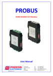
1
Web module conexio 600 Installation and operating instructions English version of original German installation and operating instructions Version: 1.0 October 2012 Table of contents 1 Description ............................................................................................................... 3 1.1 Overview................................................................................................................................................. 4 2 Fastening the web module ...................................................................................... 5 3 Connecting the device ............................................................................................. 6 4 Operating the web module...................................................................................... 7 4.1 Using the operating buttons ............................................................................................................ 7 Navigating in the menus.............................................................................................................. 7 Executing function......................................................................................................................... 7 5 Initial setup............................................................................................................... 8 Automatic configuration - dynamic IP address .................................................................... 8 Log in as user................................................................................................................................... 8 Log in as admin............................................................................................................................... 9 Manual configuration – static IP address................................................................................ 9 6 Internet access configuration................................................................................11 7 Restore settings .....................................................................................................11 8 microSD card slot ...................................................................................................12 9 Status reports and malfunctions ...........................................................................13 Displaying status reports ...........................................................................................................13 10 Technical data ........................................................ Fehler! Textmarke nicht definiert. 11 Accessories ............................................................. Fehler! Textmarke nicht definiert. 12 Declaration of conformity ..................................... Fehler! Textmarke nicht definiert. Description 1 Description The web module is used to monitor and manage networked control devices. It is operated using any Internet browser (regardless of operating system) on a PC, tablet or smart phone connected to a LAN/WLAN network. WLAN ProBus Controller LAN Web module LAN Router Internet LAN PC 3 Description 1.1 Overview microSD card interface Display Operating buttons Terminal cover Locking screw For data exchange purposes the controller is equipped with a microSD card interface (1). 4 Fastening the web module 2 Fastening the web module Use only suitable screws and dowels for fastening the controller. Hang the controller on the top screw by the keyhole (1). Fasten the controller with the screws from the inside through the bottom screw holes (2). 5 Connecting the device 3 Connecting the device LAN The web module is connected to the local network via an Ethernet connection using a switch or router. ProBus The web module is connected to system controllers via a ProBus connection. As a result, the correct polarity of the A and B terminals should be observed. M A B A B Web module Controller If you intend to use cables longer than 30m, make sure to use a terminating resistor on the terminals of the controller (see the picture). Electricity supply Connect the supplied power supply unit to the corresponding socket labelled “Power”. The web module will boot up and will be ready to use when the brand logo appears on the screen. 6 Operating the web module 4 Operating the web module Please note: Your web module needs time to boot. After switching it on always wait until the initial welcome screen appears on the Display. The main menu is located in the top part of the display. It is comprised of the following menus: Main menu Symbol Description "Info" menu The info menu shows the current status of the web module components ProBus, LAN and system. ‘OK’ means that the component is OK; ‘Error’ means than an error has occurred. "Setup" menu Reset admin password Setup Network: DHCP on or off, change the IP address Perform update Perform downgrade 4.1 Using the operating buttons Navigating in the menus To switch to the main menu, select Use or . to select the required menu. To display the various different menu items, select To exit the menu, select . Executing function To activate the displayed menu item, select To confirm the entry, select To cancel the entry, select . . To re-confirm the entry, select . 7 . or . Initial setup 5 Initial setup After the initial setup, you should immediately check for updates and update the web module firmware. To do this, login as admin, click on the menu item “Update” and follow the instructions on the screen. Automatic configuration - dynamic IP address Once connected to the router, the web module will retrieve a dynamic IP address. To be able to connect to the web module with your internet browser you need to identify this IP address in your network. You can find the retrieved IP address under the "Setup Network" menu item in the "Setup" menu of your web module. Another convenient method is to connect to your router if you have web access to it. The router displays Static and Dynamic client lists with IP address and hostname of the connected devices. For further assistance and configuration tools please visit www.helpingpoint.de/webmodule Once you found the IP address of your web module, simply type it in the URL address bar of your browser and press [Enter]. For example: If the connection has been made, the following log-in page will appear: Log in as user For the normal usage of the web module - monitor and manage your solar plant – please log in as user using the following username and password: 8 - Login: user1 - Password: 1$Resu Initial setup Log in as admin To be able to manage your device – update the firmware, configure a static IP adress, manage the user accounts etc., you should log in as Admin using the following username and password - Login: Admin - Password: nimda After your configuration is completed you should change the administrator password in order to prevent unauthorised access to the web module. Manual configuration – static IP address If you want to use a static (permanent) IP address or it was not possible to successfully complete an automatic configuration, you can perform the following manual configuration. - On your Web Module select the "Setup Network" menu item in the "Setup" menu and change the IP address and mask as desired. In the example below, to IP address 192.168.0.99, and mask: 255.255.255.000. ³ - Enter 192.168.0.99 into your browser’s URL/address bar If the connection has been made, the following log-in page will appear: 9 Initial setup Enter the following details: - Username: Admin - Password: nimda - Click in the “Log in” button The administrator menu will appear. Change and save the IP address: 10 - Click on “IP address” in the menu - Click on “Edit IP” in the menu - Enter the desired IP address and net mask Internet access configuration - If you want to create Internet connections with the web module, e.g. in order to perform online updates, enter the gateway address for your network - Enter the desired port for the web module web server. The default setting is Port 80 - Click in the “Store” button Every change of the hydraulic diagram will trigger a new initialisation of the web module. Depending on the actual configuration this process might take up to several minutes to complete. 6 Internet access configuration A location-independent connection to the web module can be created from any local or mobile Internet connection. Requirements: - The router must either have a permanent IP address or be available using a service such as no-ip.com or two-dns.de/de/. - The router must be set up in such a way that it forwards external requests to the port (factory setting 80) and IP address set up for the web module (port forwarding). 7 Restore settings In order to restore the IP address to the factory settings, select the value "DHCP" in the "Setup Network" menu item in the "Setup" menu to “on”. The factory settings will be restored and you can perform the initial network configuration again. 11 microSD card slot 8 microSD card slot Updates can be installed for the web module by inserting a microSD card. To do this, the necessary data must be available on the microSD card. Performing the relevant updates takes place using the web interface or the buttons on the device. 12 Status reports and malfunctions 9 Status reports and malfunctions Displaying status reports In order to display the status reports, go to the “Info” menu. Error message Possible cause Action ‘ProBus error’ The cable is broken or not connected correctly. Verify that the cable is correctly connected to the ProBus. If necessary, replace the cable. ‘LAN error’ Cable is connected the wrong way round. Verify the correct polarity of the A and B terminals. No connection to the switch/router/PC Verify the connection to the switch/router/PC If necessary, replace the cable. ‘System error’ Contact support 13 Technical data 10 Technical data Housing material 100 % recyclable ABS housing Dimensions L x W x D in mm 176 × 162 × 44 Protection class IP21 according to 40050, EN 60529 Operating voltage Wall power supply unit: AC 90 ... 260 V~ / 50-60 Hz Input voltage: 5 V / 1.2 A Power consumption <2W Interfaces RS 485 for ProBus, USB for WLAN and UMTS Display Back-lit LCD display Humidity max. 60 % Ambient temperature 0 to +40 °C Storage temperature –10 to +60 °C 14 Accessories 11 Accessories The following accessories are available for this device: • microSD Card Use only microSD cards from the manufacturer. The manufacturer cannot provide a guarantee that any other microSD cards will work. 12 Declaration of conformity This control unit has been manufactured and inspected according to CE regulations and thus bears the CE mark. 15 1333BED001-10B-E