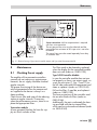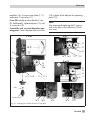
1
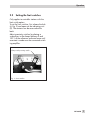
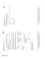
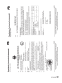
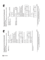
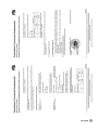
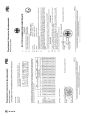
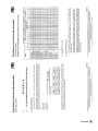
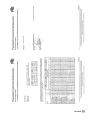
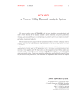
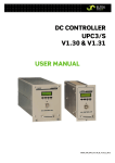
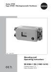
Series 430 Pneumatic Indicating Controllers Type 3430 Type 3432 Controller Station – with Type 3435 Transmitter Module for Pressure – with Type 3436 Transmitter Module for Temperature – with Type 3438 Transmitter Module for Temperature (Pt 100) – for standardized signals Version shown with lockable door and integrated Type 3436 Transmitter Module for Temperature Type 3431 Controller Station – for standardized signals Fig. 1 · Controller stations Mounting and Operating Instructions EB 7030 EN Edition October 2010 Contents Contents Page 1 Application . . . . . . . . . . . . . . . . . . . . . . . . . . . . . . . 4 2 2.1 2.1.1 2.1.2 2.1.3 2.1.4 2.1.5 2.1.6 2.2 Operation . . . . . . . . . . . Settings at the controller modules Operating action . . . . . . . . Air supply . . . . . . . . . . . Proportional-action coefficient Kp Reset time Tn . . . . . . . . . . Rate time Tv. . . . . . . . . . . Operating point. . . . . . . . . Setting the limit switches. . . . . 3 3.1 3.1.1 3.2 3.3 3.4 Commissioning . . . . . . . . . . . . . . . . . . . . . . . . . . . . . 8 Tuning the controller . . . . . . . . . . . . . . . . . . . . . . . . . . 8 Setting the operating point in P and PD controllers . . . . . . . . . . . . 9 Smooth automatic/manual mode changeover . . . . . . . . . . . . . 10 Smooth changeover between the internal and external reference variable 10 Readjusting the controller’s zero point . . . . . . . . . . . . . . . . . 10 4 Construction. . . . . . . . . . . . . . . . . . . . . . . . . . . . . . 11 5 5.1 5.2 5.3 5.3.1 5.3.2 5.4 5.4.1 5.4.2 5.4.3 5.4.4 Principle of operation . . . . . Transmitter modules . . . . . . Controller station . . . . . . . Controller modules. . . . . . . Type 3433 Controller Modules . Type 3434 Controller Modules . Additional modules . . . . . . Type 6112 i/p Converter . . . wint/wext selector switch . . . . Supply pressure regulators . . . Inductive limit switches . . . . . . . . . . . . . . . . . . . . . . . . . . . . . . . . . . . . . . . . . . . . . . . . . . . . . . . . . . . . . . . . . . . . . . . . . . . . . . . . . . . . . . . . . . . . . . . . . . . . . . . . . . . . . . . . . . . . . . . . . . . . . . . . . . . . . . . . . . . . . . . . . . . . . . . . . . . . . . . . . . . . . . . . . . . . . . . . . . . . . . . . . . . . . . . . . . . . . . . . . . . . . . . . . . . . . . . . . . . . . . . . . 11 11 12 14 14 17 18 18 18 18 19 6 6.1 6.1.1 6.2 Installation . . . . . . . . . . Mounting . . . . . . . . . . . Changing scales . . . . . . . . Installing the temperature sensor . . . . . . . . . . . . . . . . . . . . . . . . . . . . . . . . . . . . . . . . . . . . . . . . . . . . . . . . . . . . . . . . . . . . . . . . . . . . . . . . 20 20 22 22 7 7.1 7.1.1 7.1.2 7.2 Connections . . . . . . . . . . . . . . . . . . . . . . . . . . . Pneumatic connections . . . . . . . . . . . . . . . . . . . . . . Typical applications . . . . . . . . . . . . . . . . . . . . . . . Adjusting the supply air for version with supply pressure regulator. Electrical connection . . . . . . . . . . . . . . . . . . . . . . . . . . . . . . . . . . . . . . 24 24 24 25 26 2 EB 7030 EN . . . . . . . . . . . . . . . . . . . . . . . . . . . . . . . . . . . . . . . . . . . . . . . . . . . . . . . . . . . . . . . . . . . . . . . . . . . . . . . . . . . . . . . . . . . . . . . . . . . . . . . . . . . . . . . . . . . . . . . . . . . . . . . . . . . . . . . . . . . . . . . . . . . . . . . . . . . . . . . . . . . . . . . . . . . . . . . . . . . . 4 4 4 5 6 6 6 6 7 Contents 8 8.1 Maintenance . . . . . . . . . . . . . . . . . . . . . . . . . . . . . 27 Checking the air supply . . . . . . . . . . . . . . . . . . . . . . . . 27 9 9.1 9.2 9.3 Conversion . . . . . . . . . . . . Changing the controller function . . Exchanging the transmitter module . Checking the controller function . . 10 10.1 Use in hazardous areas . . . . . . . . . . . . . . . . . . . . . . . . 31 Servicing explosion-protected devices . . . . . . . . . . . . . . . . . 31 11 Technical data . . . . . . . . . . . . . . . . . . . . . . . . . . . . 32 . . . . . . . . . . . . . . . . . . . . . . . . . . . . . . . . . . . . . . . . . . . . . . . . . . . . . . . . . . . . . . . . . . . . . . . . 28 28 30 30 Certificates . . . . . . . . . . . . . . . . . . . . . . . . . . . . . . 35 General safety instructions 4 The device may only be assembled, started up or operated by trained and 4 4 4 experienced personnel familiar with the product. According to these mounting and operating instructions, trained personnel is referred to as individuals who are able to judge the work they are assigned to and recognize possible dangers due to their specialized training, their knowledge and experience as well as their knowledge of the relevant standards. Explosion-protected versions may only be operated by personnel who have undergone special training or instructions or who are authorized to work on explosion-protected devices in hazardous areas. Any hazards that could be caused by the signal pressure are to be prevented by means of the appropriate measures. Proper shipping and appropriate storage of the device are assumed. EB 7030 EN 3 Application 1 Application The Series 430 Pneumatic Indicating Controllers are used for applications in process automation and industrial plants. The controllers directly measure the controlled variables (pressure, temperature, electric or pneumatic standardized signal) and display the value. They compare the measured variable with the set point and issue a corresponding pneumatic control signal from 0.2 to 1 bar (3 to 15 psi). A supply pressure of 1.4 bar ± 0.1 bar (20 psi ± 1.5 psi) is required or an operating pressure of 2 to 12 bar (30 to 180 psi) when a supply pressure regulator is installed. 2 Operation 2.1 Settings at the controller modules The controller module in the station can be accessed after the lock (Fig. 2) has been released and the indicating unit (5) has been opened out. The settings for operating action (turnboard A) and air supply (turnboard B) must be performed prior to commissioning. 4 Unscrew the mounting screw (6) on the controller module. Pull it off its self-sealing hose fittings and lift out of the controller station. 2.1.1 Operating action The operating action for the control loop is set at the turnboard A (Fig. 2), where the position of its arrow symbol according to the arrow symbol on the controller module determines the operation action of the controller. 4 EB 7030 EN 34 Arrow tips facing opposite directions: Operating direction: Increasing/decreasing = As the controlled variable x increases, the output signal pressure y decreases. 44 Arrow tips facing the same direction: Operating direction: Increasing/increasing As the controlled variable x increases, the output signal pressure y increases. Operation Setting or modifying the operating direction: 2.1.2 Air supply Unfasten the screw in turnboard A (Fig. 2) and lift it off together with the turnboard. If necessary, lever the board at the side. Do not lose the rubber seal. (only with Type 3433 Controller Module) The position of the turnboard B (Fig. 2) with its arrow symbol determines the air supply to the feedback bellows. It can be accessed after the comparator (3.1) has been removed. 4 Turn the board by 90° so that the re4 4 quired arrow is aligned with the arrow on the base plate. Insert board and tighten screw. Reassemble the controller module in the controller station. 1 1.3 1.1 4 1.4 1 1.1 1.3 1.4 2 5 3 3.1 3.2 3.3 3.4 2 Air supply Oper. action B A 3.2 4yA Normal air supply, approx. 1 mn³/h per % of the system deviation 4R Large air supply, approx. 3 mn³/h per % of the system deviation (not with P or PD controller modules) Controller station (Type 3432) Scale Actual value pointer (red) Set point adjuster Transmitter module or connecting base Controller module Comparator Connecting plate Hex screws Screws (inside) 3.4 8 9 3.1 6 4 5 6 7 8 9 10 11 Lock Indicating unit Mounting screw Restriction Zero adjuster Kp adjuster Tn adjuster Tv adjuster (only in PD or PID controller) 12 Operating point adjuster (only in P or PD controller) 3 10 9 3.3 3 6 7 Type 3432 Contr. Module Side view without comparator 10 12 11 Oper. action A 8 Type 3433-2 (PI) Controller Module Type 3434-2 (PI) Controller Module Fig. 2 · Turnboards and adjusters EB 7030 EN 5 Operation 4 Unfasten screws (3.3) and pull off the connecting plate (3.2) together with nuts and bolts from the controller module. Unscrew the hexagonal socket-head screws (3.4) at the side and lift the comparator (3.1) out of the controller module. Setting or modifying the air supply: 4 4 Unfasten screw in turnboard B and lift it 4 4 off together with the turnboard. If necessary, lever the board at the side. Do not lose the rubber seal. Turn the board so that the arrow is aligned with the mark yA or R on the controller module. Insert board and tighten screw. Reassemble the controller module in the controller station. 2.1.3 Proportional-action coefficient Kp The setting of the KP (adjuster 9) determines the controller gain and is related to the controlled system that is being tuned (section 3.1). 2.1.4 Reset time Tn Controller versions with integral-action component require the reset time to be set at the restriction (10). The setting depends on the controlled system that is being tuned (section 3.1). 6 EB 7030 EN 2.1.5 Rate time Tv For Type 3433 Controller versions with derivative-action component, the rate time Tv needs to be set at the restriction (11). The setting depends on the controlled system that is being tuned (section 3.1). 2.1.6 Operating point Controller modules without integral-action component such as P or PD controllers have an operating point. In Type 3433 Controller Module, it can be adjusted between 0 and 100 % which corresponds to 0.2 to 1 bar by an operating point adjuster (12). The setting depends on the manipulated variable y (section 3.1.1). In Type 3434 P Controller Module, the operating point is fixed at 0.6 bar. Operation 2.2 Setting the limit switches Only applies to controller stations with the limit switch option: To set the limit switches, first release the lock (4, Fig. 2) and open out the indicating unit (5). The contacts can be accessed at the back. Adjust proximity switches by placing a screwdriver in the clamps between 0 and 100 % of the reference scale and move until a contact is made over the connected switching amplifier. Clamps with proximity switch Fig. 3 · Limit switches EB 7030 EN 7 Commissioning 3 Commissioning Prior to commissioning the control loop, check all devices to make sure they are connected correctly, do not leak and function properly. Release lock (4) and open out the indicating unit (5) to enable easy access to the operating controls at the controller. Check the turnboard to make sure the correct operating action is set at the controller (see section 2.1.1). 3.1 Tuning the controller The controller needs to be tuned to the characteristics of the controlled system using the KP and Tn and/or Tv adjusters at the controller module to ensure that the controller can keep any system deviations for all set points caused by the disturbance variables to zero or at least to minimize them. In case of controller stations which have a manual/ automatic switch (1.6), the plant must be started up manually. We recommend to determine the settings by using a tuning test (following the Ziegler and Nichols method) which produces sufficient results in most cases: 1. Apply supply air (1.4 ±0.1 bar). 2. Set the proportional-action coefficient KP to a low value at the comparator. 3. Set Tn restrictor to its maximum value and Tv to its lowest value (applies only to PI and PID controllers). 8 EB 7030 EN 1.8 1.3 1.6 1.4 1.5 4 1.7 5 1.3 Actual value pointer (red) 1.4 1.5 Set point adjuster with green pointer Signal pressure display 1.6 Manual/automatic switch 1.7 1.8 Adjuster for signal pressure (manual) Differential pressure indicator 4 5 Lock Indicating unit Fig. 4 · Front view Setting in manual mode: 4. Set manual/automatic switch to Manual. 5. Operate manual adjuster (1.7) for the control signal so that the controlled variable (actual value pointer 1.3) slowly settles on the adjusted set point (set point pointer 1.4). Should the differential pressure indicator (1.8) move to zero, set the manual/automatic switch (1.6) to Automatic. Proceed as described in points 6 and 7. Setting in automatic mode: 4. Set the set point to the required value at the rotary knob (1.4) on the indicating unit. 5. Set the Tn restriction briefly to its lowest value (completely open) to move the red Commissioning actual value pointer to the green set point pointer. Close the Tn restriction again. 6. Starting from a low value, increase the proportional-action coefficient KP until the actual value pointer displays an harmonic oscillation pattern (uniform oscillation amplitudes as shown in Fig. 5) of the controlled variable. If oscillations do not arise with a large KP setting, turn the rotary knob to change the set point slightly and then return it to its former setting. It may be necessary to increase the gain (KP) slightly until an harmonic oscillation pattern arises. 7. Write down the adjusted value of the KP scale you have just adjusted as the critical proportional-action coefficient KPkrit. Use a stopwatch to time the oscillation time for one entire oscillation as Tkrit (PI and PID controller only). Controlled variable (actual value) Tkrit Multiply both values with the values in the table (Fig. 5) and set as the favorable settings for KP, Tn, and Tv at the controller. Should oscillations still occur despite these settings, slightly reduce KP and increase Tn. Repeat these steps, if necessary, until the control loop shows a satisfactory performance. Leave enough time in between setting to allow the controller to stabilize. 3.1.1 Setting the operating point in P and PD controllers (Type 3433 Controller Module only) After setting the proportion-action coefficient KP as described previously, set the operating point for P and PD controllers instead of the reset time Tn. 4 Read off the controlled variable yA of the 4 controller at the display (1.5) when the plant is in a steady-state condition and set this value directly at the operating point adjuster (12, Fig. 2). (Setting 0.2 to 1 bar = 0 to 100 %). Recorrect slightly until the system deviation is zero. In case the signal pressure display deviates, average the value. + – Tkrit Cntr. KP P 0.50 · KP,krit Tn PI 0.45 · KP,krit 0.85 · Tkrit PID 0.59 · KP,krit 0.50 · Tkrit Tv Note! On changing set point or reference variable, the operating point must be set again as described above. If the reference variable is changed more often, set the operating point to 0.6 bar = 50 % (average value). 0.12 · Tkrit Fig. 5 · Harmonic oscillation, settings EB 7030 EN 9 Commissioning Note! The Tn restriction must be completely opened with a P/PI controller is switched over to P action to allow the operating point adjuster to work without delay. Version with w-dependent operating point This version does not need to be adjusted since the operating point automatically follows the set point w. 3.2 Smooth automatic/manual mode changeover (only for controller station with manual/automatic changeover, Fig. 4) The smooth switchover ensures that no pressure surges can reach the valve when the manual/automatic switch is activated as follows: Changeover from automatic to manual Use the manual adjuster (1.7) to adjust signal pressure manual yH until the differential pressure indicator (1.8) is zero. Switch over to manual at the switch. Differential pressure indicator With Without deviation Changeover from manual to automatic If the plant is to be controlled manually to the required value, the automatic signal pressure yA must be matched to the manual signal pressure yH by adjusting the set point 10 EB 7030 EN adjuster (1.4). The switch (1.6) can only be set to automatic after the differential pressure indicator (1.8) is at zero. Set the set point again to the required value. 3.3 Smooth changeover between the internal and external reference variable When combining the fixed set point control and follower control, the Type 3432 Controller Station is equipped with a wint/wext switch, a pressure adjuster and a differential pressure indicator (Fig. 10). The differential pressure indicator must first be brought to zero by activating the pressure adjuster in order to switch between the reference variables. 3.4 Readjusting the controller’s zero point Should deviations arise between the actual value and set point during operation, the zero point adjustment can be readjusted by turning the zero screw at the back of the display unit (5) until the actual value and set point on the front display are the same again. Deviations between the actual value and set point can also be corrected at the zero point adjuster (8, Fig. 2) of the controller module. Construction 4 Construction The controllers designed according to the modular principle form an entire automation unit consisting of a controller station, a controller module tuned to the local conditions, and, where applicable, a transmitter as well as other additional modules. Controllers with Type 3432 Controller Station are mainly designed for installation of a Type 3435 Transmitter Module for Pressure or a Type 3436 Transmitter Module for Temperature with direct process fluid connection. The Type 3431 Controller Station receives the controlled variable as a standardized signal from 0.2 to 1 bar or 3 to 15 psi. The controlled variable can also be supplied as a current signal from 4 or 0 to 20 mA or 1 to 5 mA over an integrated i/p converter. The controller station can be equipped with the Type 3433 or Type 3434 Controller Module. For special control applications, the Type 3433 Controller Module can be combined with Type 3437 Additional Modules for pressure limitation, control mode switchover or smooth manual/automatic transfer. The controller station can also be upgraded, if required, with a manual/automatic transfer, consisting of a selector switch, adjuster for manual mode, and differential pressure indicator. The controller station must be equipped with an additional module for wint/wext changeover when used for applications as a combined fixed set point controller and follower controller. An additional pneumatic or electric output for the external reference variable wext (e.g. 0.2 to 1 bar or 4 (0) to 20 mA) is likewise required when used as a follower controller. Additionally, inductive limit switches, that are adjustable at a scale, can be mounted on the indicating units 1 or 2. Note! Refer to the corresponding Data Sheets for details about the controller stations and their controller modules. T 7030 EN · Pneumatic Indicating Controllers - Information Sheet with product overview. T 7032 EN · Pneumatic Indicating Controllers for Pressure T 7034 EN · Pneumatic Indicating Controllers for Temperature with Capillary Sensor T 7036 EN · Pneumatic Indicating Controllers for Temperature with Pt 100 Resistance Thermometer T 7038 EN · Pneumatic Indicating Controllers for Standardized Signals T 7040 EN · Type 3433 Pneumatic Controller Modules and Type 3437Additional Modules T 7041 EN · Type 3434 Pneumatic Controller Modules T 7045 EN · Type 6112 i/p Converter Module 5 Principle of operation 5.1 Transmitter modules Type 3435 for Pressure The process fluid pressure p is transmitted to the transmitter module (2) where it causes a deflection at the Bourdon tube measuring EB 7030 EN 11 Principle of operation system (2.1). The deflection is converted by the pneumatic servo system (2.2) into a pneumatic signal (controlled variable x) which is proportional to the pressure p. The signal is transferred to the bellows measuring system of the actual value display (1.3) as well as to the controller module (3). Type 3436 for Temperature with capillary sensor The temperature of the medium produces a pressure in the gas-filled sensor (2.3) of the transmitter module which is proportional to the temperature. This pressure is offset by a force on the beam (2.4) and converted into the output pressure pA at the feedback bellows (2.6). The supply air flows over the restriction (2.9) and nozzle (2.8) and hits the flapper (2.7). As the temperature rises, the flapper moves closer to the nozzle. This results in an increase in output air pressure pA supplied to the bellows (2.6) until a new state of equilibrium is reached, i.e. until the output signal is proportional to the temperature measured. This signal is transmitted as the actual value signal (controlled variable x) to the bellows measuring system of the actual value display (1.3) and the controller module (3). Type 3438 for Temperature with Pt 100 resistance thermometer The Type 3438 Transmitter Module consists of an electric transmitter and a downstream i/p converter to connect a Pt 100 sensor. The resistance value of the Pt 100 sensor is converted into a 4 to 20 mA current signal in the electric transmitter. Its output signal (4 to 20 mA) is converted into a pneumatic signal between 0.2 and 1 bar by the i/p converter. The output pressure, which is proportional to the temperature, is supplied to the 12 EB 7030 EN bellows measuring system of the controlled variable display and the controller module as a pneumatic controlled variable signal (controlled variable x). 5.2 Controller station The actual value signal x causes a deflection at the bellows measuring system of the actual value display (1.3) which is transmitted to the pointer over a gear mechanism. The set point (reference variable w) can be adjusted at the scale (1.2) on the front. The position of the set point adjuster (1.4) is transmitted to the set point transmitter over a gear mechanism. This pneumatic servo system (1.41) converts the adjusted set point into a pneumatic set point signal (w) which is transmitted to the controller module. The controller module compares the actual value signal (x) with the set point signal (w) and controls using the control signal yA depending on the system deviation and the adjusted control parameters. The control signal is connected to the signal pressure display (1.5) and the output port y. The controller station with manual/automatic switchover (Figs. 2 and 4) additionally features a manual/automatic switch (1.6), an adjuster for manual mode (1.7), and a differential pressure indicator (1.8). Signal pressure display (1.5) and output port y are connected to the automatic output signal yA with a switch position at “Automatic” and to the manual output signal yH set at the adjuster (1.7) with a switch position at “Manual”. A smooth switchover from manual to automatic mode is possible when the differential pressure indicator (1.8) shows that yA and yH are identical. Principle of operation 1.41 1.2 1.4 1.3 1.5 x w 1 y 1.5 3 1.41 1.2 1 R w z PI P yA P/PI S PID x w 1.4 1.3 x w 3 R w z PI P yA P/PI S PID x w 2.4 2.7 2.1 2 Z 2.6 y 2.2 Type 3432 with Type 3435 Transmitter for Pressure 1.5 1.2 1.4 1.3 x w 1 y y Z 2.3 Type 3432 with Type 3436 Transmitter for Temperature 1.41 1.2 1.4 1.3 1.8 3 yH R yA 3 x w R S w z PI yA P P/PI S PID x w 2.9 2.8 w z PI yA P P/PI S PID x 1.6 1.5 1.7 4 w yH x Z 1 Z 1.9 x x y PB Type 3431 and 3432 for pneumatic standardized signals 1 Controller station 1.2 Scale 1.3 Actual value display with pointer, gear mechanism and bellows measuring system 1.4 Set point adjuster with pointer, gear mechanism and set point (1.41), set point display only for follower controllers 1.5 Signal pressure display Type 3432 with manual/automatic switch (1.6), supply pressure regulator (1.9) and i/p converter 1.8 Differential pressure indicator for smooth manual/automatic switchover 1.9 Supply pressure regulator 2 Transmitter module 2.1 Bourdon tube meas. system 2.2 Pneumatic servo system 2.3 Temperature sensor 2.4 Beam 2.6 Feedback bellows 2.7 2.8 2.9 3 4 Flapper Nozzle Restriction Controller module Type 6112 i/p Converter Z = Supply pressure 1.4 bar PA = Output pressure PB = Compressed air network Fig. 6 · Principle of operation of controllers EB 7030 EN 13 Principle of operation 5.3 Controller modules The controller modules are designed as plug-in units. They are inserted into the self-sealing hose fittings of the controller station and fastened in place by mounting screw. 5.3.1 Type 3433 Controller Modules The controller modules consist of the comparator equipped with four metal bellows arranged in a square and the base plate with plug-in connections. The base plate contains the components necessary for the corresponding function such as relays and restrictors. The components can be exchanged or retrofitted to upgrade a device (refer to section 9.1 for more details). Type 3433-2 PI Controller (Fig. 7, top) The controlled variable x (actual value) and the reference variable w (set point) are transmitted as pneumatic signals between 0.2 and 1 bar to metal bellows w und x over the turnboard A. When x is greater than w, the actual value bellows tilts the swashplate at its pivot towards the set point bellows. This causes the pressure to rise downstream of the nozzle which is connected to the swashplate over a pin and, as a result, the comparator increases the output pressure yA. The output pressure is fed back over turnboard B to the bellows R2 on the swashplate. The pressure and the position of the swashplate continue changing until the distance between the nozzle and flapper achieve the initial value and the output pres- 14 EB 7030 EN sure yA reaches the value related to the controlled variable x and the proportional-action coefficient Kp set at the screw. Outside of the controller module, yA is connected to R, meaning that the output pressure yA is also fed back to bellows R1 over port R and the adjustable Tn restriction. As a result, the effect caused by the pressures in bellows R1 and R2 is balanced and system deviation is eliminated. Should a switching pressure exist at port S after switching the controller station to manual mode, the Tn restriction is bypassed by the Tn start-up relay. Turnboard A determines the operating action of the controller which can be changed by turning the board. Refer to section 2.1.1. Turnboard B determines the air supply to the feedback bellows. In delivered state, it is set to yA, i.e., the output pressure is directly fed back to bellows R2, whereas, it is fed to bellows R1 over the manual control unit to port R. This arrangement provides the controller with a normal air supply and a damping of the output pressure. Setting it to R results in the output pressure yA being fed back to bellows R1 and R2 over port R which provides a higher air supply. This type of turnboard setting is suitable for applications where the distance to the final control element is long and the connected volume is large as well as where controlled systems react quickly. Refer to section 2.1.2 to set or change the air supply by turning the turnboard B. Principle of operation 0.2 Kp 20 0.2 Kp Type 3433-2 PI Controller Module The following versions of the controller modules are similar in most aspects to the Type 3433-2 PI Controller Module, however, they are fitted with, for example, an operating point adjuster, derivative element, or a selector switch, depending on the application. Type 3433-1 P Controller Module corresponds to Type 3433-2. An operating point adjuster is used in place of the integral element. 20 0.2 Kp 20 R Feedback R1/R2 Feedback bellows Z = Supply air 1.4 bar Output pressure YA S Switching pressure A B Type 3433-3 PID Controller Module corresponds to Type 3433-2. Additionally, it contains a derivative element which produces the rate action with approximately ten times the gain in the input branch of the controlled variable x. The rate time can be adjusted at the TV restriction. Turnboards Operating action Air supply Fig. 7 · Type 3433 Controller Modules EB 7030 EN 15 Principle of operation Type 3433-4 PD Controller Module corresponds to Type 3433-1. Additionally, it contains a derivative element which produces the rate action with approximately ten times the gain in the input branch of the controlled variable x. The rate time can be adjusted at the TV restriction. 0.2 Kp 20 Type 3433-5 P/PI Controller Module with P/PI selector switch can optionally be used as a P controller with operating point adjustment or as a PI controller. The structure is the same as that of the PI and P controller module. Type 3433-6 PD/PID Controller Module with PD/PID selector switch can optionally be used as a PD or PID controller. 0.2 Kp 20 Type 3433-9 P Controller Module with set point-dependent operating point corresponds to Type 3433-1 P Controller Module, except that the operating point shifts proportional to the set point w. 0.2 Kp 20 Fig. 8 · Type 3433 Controller Modules 16 EB 7030 EN Principle of operation The effect caused by the pressures in the diaphragm chambers R1 and R2 is balanced. The position of the force switch continues to change until the controller output pressure reaches a value which is related to the controlled variable x and the adjusted proportional-action coefficient Kp, i.e. until the system deviation is eliminated. The proportional-action coefficient Kp is adjusted at the restriction (9) and the reset time Tn at the restriction (10). The zero point adjuster (8) is used to tune the device. The turnboard A determines the controller’s operating action which can be changed by turning the board (section 2.1.1). 5.3.2 Type 3434 Controller Modules The controller modules have a round comparator which operates according to the force-balance principle. The proportional-action coefficient Kp can be adjusted in the range between 1 and 25. Type 3434-2 PI Controller Module (Fig. 9) Controlled variable x and reference variable w are transmitted as pneumatic excess pressures between 0.2 and 1 bar or 3 and 15 psi to the diaphragm chambers (R1 and R2) over the turnboard A. When x is greater than w, the force switch (23) lowers and the plug opens. Supply air flows into the diaphragm chamber R2 and the output pressure yA increases. This pressure is transmitted over the Tn restriction (10) to the volume of the 1:1 booster (24). Its output pressure is fed back to the diaphragm chamber R1. 24 10 9 Type 3434-1 P Controller Module The design and principle of operation are the same in most aspects to Type 3434-2 PI Controller Module. However, a spring for an operating point fixed at 0.6 bar is used instead of the feedback with Tn restriction. 8 R w A Z yA Kp R1 21 R2 Tn S 23 8 9 10 21 23 24 Zero point adjuster KP adjuster Tn adjuster Diaphragms Force switch Booster R1 Diaphragm chamber R2 Diaphragm chamber A Turnboard for operating action x Fig. 9 · Type 3434-2 Controller Module EB 7030 EN 17 Principle of operation 5.4 Additional modules 5.4.1 Type 6112 i/p Converter External reference variable wext and/or controlled variable x can be issued as a current signal of 4(0) to 20 mA or 1 to 5 mA and converted by the i/p converter into a pneumatic standardized signal of 0.2 to 1 bar. The i/p additional module with one or two converters is integrated into the controller station and can only be used in conjunction with the Type 3433 Controller Modules. Connecting plate with two i/p converters for controlled variable x and external set point 5.4.2 wint/wext selector switch When used as a combination of fixed set point controller and follower controller, the controller is fitted with a wint/wext selector switch. The associated set point adjuster and differential pressure indicator allow a smooth switchover when the indicator is at zero. Refer to section 3.3. 5.4.3 Supply pressure regulators Adjuster for internal set point When a supply pressure regulator is mounted onto the Type 3432 Controller Station, it is suitable for the connection to an operating pressure of 2.0 to 12 bar. The Type 3708-5003 Supply Pressure Regulator (Var.-ID 1023317) reduces and controls the operating pressure to the required supply pressure of 1.4 bar. wint/wext selector switch Supply pressure regulator Fig. 10 · Additional modules 18 EB 7030 EN Principle of operation 5.4.4 Inductive limit switches The inductive limit switches indicate when the controlled variable x exceeds and/or falls below an adjustable limit value. Two metal tags are mounted to the pointer shaft of the controlled variable x which activate associated proximity switches. When the metal tag moves into the field of the inductive pick-up, it is highly resistive and when the metal tag moves outside of the field, it is low resistive. The proximity switches are located in adjustable brackets. The required switching point can be adjusted by turning the brackets. Refer to section 2.2 for more details. EB 7030 EN 19 Installation Installation 6.1 Mounting The controller station is designed for mounting onto pipes, walls or in panels. Refer to Figs. 11 and 12 for the corresponding dimensions. Pipe mounting Mounting to vertical or horizontal 2" pipes using a mounting part with bracket. Required mounting kit: Order no. 1400-6302. Protective roof (accessories): Order no. 1400-6311 192 Active sensor length Air sensor Protective roof Mounting plate 8 6 Bracket Ø19.5 G¾ 228 300 Pipe 2” 425 400 300 Ø12 31 30 30 30 40 16 45 69 26 27 8/9 38 160 28 13 228 29 36 10 Ports: 26 x Controlled variable 27 wext Ext. set point 8/9 Supply air Z 38 y Manipulated variable 10 241 Type 3432 with Type 3436 Temperature Transmitter 124 Ø7 5 Air connections 160 26 27 8/9 38 Tapped ports ISO 228/1-G 1/8 Process fluid connection Type 3432 with Type 3435 Pressure Transmitter Fig. 11 · Installation dimensions of Type 3432 Controller Station 20 EB 7030 EN 8 Cable gland M 20x1.5 28 13 Installation Panel mounting Mounting using four mounting elements (DIN 43835). Distance between centers to door approx. 235 mm. Close arrangement in rows without door acc. to DIN IEC 61554 (DIN 43700). Type 3432: Panel cut-out 188+1 x 255+1 mm, Required panel mounting kit: Order no. 1400-6300. Type 3431: Panel cut-out 188+1 x 138+1 mm, Required panel mounting kit: Order no. 1400-6303 Protective roof (accessories): Order no. 1400-6311 Protective roof 192 8 Wall mounting Mounting using three straps Required mounting kit: Order no.1400-6301 Mounting plate 144 Bracket Pipe 2” 45 69 26 27 8/9 38 Pipe 2” 124 Ø7 160 28 13 10 10 Ports: 26 x Controlled variable 27 wext Ext. set point 8/9 Supply air Z 38 y Manipulated variable 241 144 Cable glands M20x1.5 16 8 30 30 30 5 28 26 27 8/9 38 160 Air connections Tapped ports ISO 228/1-G 1/8 13 Fig. 12 · Installation dimensions of Type 3431 Controller Station EB 7030 EN 21 Installation 6.1.1 Changing scales After unlocking the door (4, Fig. 4), the scale can be removed from the back of the display and, if necessary, replaced with a special scale. The scale division of the scale must match the measuring range of the connected or integrated transmitter. Adhesive strips are attached to inside the casing for tag labeling on the scale. 4 Cut the strips to size and stick them on the scale. 6.2 Installing the temperature sensor Only applies to controller stations with Type 3436 Transmitter Module Bulb sensor Ø 12 mm, length 425 mm (active length 300 mm) The bulb sensor can be installed in any position. However, the entire length of the sensor must be immersed in the medium to be controlled. Choose a point of installation where overheating or noticeable time delays cannot occur. Run the capillary tube in such a way that the large temperature deviations cannot occur (ambient temperature approx. 20 °C) and the tube cannot be damaged. The smallest possible bending radius is 50 mm. A sleeve with G ½ or G ¾ female thread at the point of measurement is required to install the sensor. Screw or seal one of the mounting parts shown in Fig. 13 into this sleeve. Note! The mounting parts are not included with the sensor. They must be ordered separately. Select which mounting parts are needed depending on the operating conditions at the point of measurement. 22 EB 7030 EN Installation Ø50 55 75 Ø26 Clamping flange For wall mounting, e.g. pressureless containers or ducts 32 Ø9.5 8 Ø12 Mounting parts for bulb sensor Ø 12 mm, length 425 mm Order no. 1090-9547 Mount flange to wall using two screws and attach temperature sensor with two other screws in the flange. G Screw gland (PN 10) G ½ Order no. 1080-4881 G ¾ Order no. 1080-4882 Fill screw fitting with sealant. Insert sensor with screw gland and coupling nut. Tighten coupling nut. G¾ SW 32 G Screw gland (PN 40) with clamping nut G ½ Order no. 1080-4884 G ¾ Order no. 1080-4885 Install as described above. Tighten clamping nut instead of coupling nut. 12 30 1 36 Ø16 G SW 32 385 SW 32 Thermowell for welding (PN 63) Order no. 1080-4890 375 SW 32 Ø21.3 Thermowell with flange Order no. 1080-4891 (PN 40) 1080-4892 (PN 100) G¾ Ø21.3 Thermowell with thread (PN 63) G ½ Order no. 1080-4888 G ¾ Order no. 1080-4889 Use a thermowell when the nominal pressure is exceeded, when corrosive media are involved or when the plant is to continue to run while the sensor is being replaced. Insert sensor right to the bottom of the thermowell. Tighten coupling nut. SW 32 Note: All wetted parts of the screw gland and thermowells are made of stainless steel 1.4571. Fig. 13 · Mounting parts for bulb sensor 335 40 EB 7030 EN 23 Connections 7 Connections 7.1 Pneumatic connections 7.1.1 Typical applications The air connections underneath the device are designed as bores with ISO 228/1G 1/8 thread. The customary fittings for pipes or plastic hoses can be used. Note! The supply air must be dry and free from oil and dust. The maintenance instructions for upstream pressure reducing stations must be observed. Blow through all air tubes and hoses thoroughly prior to connecting them. The connection designations with codes are cast underneath the housing. They can additionally be marked on the back of the housing using the adhesive label supplied with the controller station. 38 Output y – Manipulated variable, Output signal of the controller to operate the control valve or positioner. 8/9 Supply – Supply air , Supply air 1.4 ±0.1 bar or 2 to 12 bar for the version with supply pressure regulator (see section 5.4.3). 27 Input wext – External reference variable, Closed with fixed set point controller and open for the connected external set point with follower controller. 26 Input x – Controlled variable, Closed with pressure or temperature controller (controlled variable is recorded by the transmitter module). Open with standardized controllers. 24 EB 7030 EN Controller for standardized signals MU – Transmitter STR – Positioner 26 8/9 38 MU x Z y 0.2...1 bar Supply 0.2 ...1 bar STR Temperature controller (with Type 3436) Sensor 8/9 38 Z y Supply 0.2 ...1 bar STR Pressure controller (with Type 3435) 8/9 38 Z y Supply 0.2 ...1 bar Process fluid connection to measure pressure: Connection to pipe, pressure vessel, etc. Fig. 14 · Standard applications STR Connections 7.1.2 Adjusting the supply air for version with supply pressure regulator Only applies to Type 3432 Controller Stations with supply pressure regulator (1.9). Hose connections for supply air are located directly above the corners of the supply pressure regulators on the bridge of the connecting plate (inside housing). The connections are sealed by the hose end fittings. 4 Pull left end fitting off and use a hose to connect it to a test pressure gauge. 4 Controller stations with a manual/auto4 Fig. 15 · Test connection with test connector matic selector switch have a test connection (yellow) inside the indicating unit. Use the enclosed test connector for this version (Fig. 15). Unscrew cap of the pressure controller. Undo the lock nut on the spindle and adjust the spindle: 4 Turn the spindle clockwise to increase the supply pressure and counterclockwise to reduce it. 4 Secure the position of the spindle with the lock nut and screw the cap back on when the supply pressure at the test pressure gauge indicates a pressure of 1.4 ±0.1 bar (20 ±1.5 psi). EB 7030 EN 25 Connections The electrical components only apply to controller stations with i/p converter additional modules for controlled variable x, external reference variable wext and/or with inductive limit switches. Caution! For electrical installation, you are required to observe the relevant electrotechnical regulations and the accident prevention regulations that apply in the country of use. In Germany, these are the VDE regulations and the accident prevention regulations of the employers' liability insurance association. The following standards apply for assembly and installation in hazardous areas: EN 60079-14: 2003 (VDE 0165 Part 1/8.98) "Electrical apparatus for explosive gas atmospheres" and EN 50281-1-2: 1999 (VDE 0165 Part 2/11.99) "Electrical apparatus for use in the presence of combustible dust". For the interconnection of intrinsically safe electrical equipment, the permissible maximum values specified in the EC type examination certificate apply (Ui or U0; Ii or I0; Pi or P0; Ci or C0, and Li or L0). Note! The terminal assignment specified in the Mounting and Operating Instructions must be adhered to. Reversing the assignment of the electrical terminals may cause the explosion protection to become ineffective. Do not tamper with painted screws. 26 EB 7030 EN Note on the selection of cables and wires: To install intrinsically safe circuits, observe section 12 of the standard EN 60079-14: 2003 (VDE 0165 Part 1). To run multi-core cables or lines with more than one intrinsically safe circuit, section 12.2.2.7 of this standard applies. Devices used at ambient temperatures down to –40 °C must have metal cable entries. The terminals on the base plate can be accessed after unscrewing the front cover beneath the display. For operation of the limit switches, switching amplifiers which comply with EN 60947-5-6 must be connected in the output circuit. Type 3432 Controller Station i/p converter 12 11 – + x 21 22 42 41 52 51 + – wext 4(0)...20 mA – + – + Sw. amplifier Limit switches Type 3431 Controller Station i/p converter + – + – Sw. amplifier 22 21 11 12 Electrical connection 42 41 52 51 7.2 – + + – wext x 4(0)...20 mA Limit switches Fig. 16 · Connecting i/p converters and limit switches Maintenance Type 3438 W YH T I – + + – I 4...20 mA + L N PE – 3 4 11 12 13 14 24V– EEx i + + Safe area – 3 4 Pt 100 – EEx i Z 8/9 Y 38 Wext 27 Output External Setpoint – ϑ – PID P Supply + ~ X YA + Ex zone 1 Sensor connection: No line compensation is required with four-wire connection. The resistance of the wires must be identical and the permissible line resistance of 50 W per wire is not to be exceeded. The sensor lines are to be routed separately from relay or contactor lines. Fig. 17 · Electrical wiring of Type 3432 Controller Station with Type 3438 Transmitter Module 8 Maintenance 8.1 Checking the air supply The modules of the pneumatic controllers normally do not require any maintenance. However, the air supply should be checked regular intervals. The proper functioning of the device can only be guaranteed when the compressed air supplied to the device is always in a clean condition. Check the air filter and traps of the reducing station at regular intervals. If necessary, when the performance worsens, clean or replace the appropriate filters. Transmitter module: A hose grommet fitted on the hose for supply air which includes a filter. This filter needs to be cleaned or replaced when the display for the controlled variable does not work (order no. 0550-0193). Type 3433 Controller Module: In case the controller module does not control properly or there is no output signal, unscrew the restriction (7, Figs. 2 and 17) on the left side underneath the comparator and clean or replace it (order no.1390-0183). Pull out the filter, if need be, and replace it (order no. 0550-0193). The hose connections of the controller module are also fitted with filters (order no. 0550-0186). Additionally, the ports underneath the housing are fitted with plastic-rimmed filters which can be unscrewed and cleaned (order no. 0550-0189). EB 7030 EN 27 Conversion 9 Conversion 4 Undo bolts (3.3) and pull connecting 9.1 Changing the controller function 4 The controller function can be changed either by exchanging the entire module (Type 3434-1 or Type 3434-2) or by upgrading or altering (Type 3433) components such as adjusters, restrictions or differential amplifier. Type 3433 Controller Module: 4 Unscrew the mounting screw (6) at the controller module and pull it off the self-sealing hose fittings. Remove it from the controller station. Part plate (3.2) together with bolts and hex nuts off the controller module. Detach and mount the corresponding cover plates and adjusters by unfastening the M3 hexagon socket head screws inside the housing. P into PI: Unscrew adjuster for operating point (12) and replace it with Tn restriction (10). P into P/PI: Unscrew adjuster for operating point (12) and replace it with a selector switch with operating point adjuster (13) and Tn restriction (10). P into PD: Unscrew cover plate (14.1). Take out O-ring (14.3) and insert two O-rings (14.4) in its place. Screw on differential Quantity Designation Order no. 10 10.1 10.2 1 2 3 Tn restriction Screws M3x8 O-rings 1.78 x 1.02 1070-4584 8333-0479 8421-0010 11 11.1 11.2 11.3 1 1 2 4 Tv restriction Cover plate Screws M3x8 O-rings 2 x 1.5 1070-4585 0360-1597 8333-0479 8421-0023 12 12 12.1 12.2 1 1 2 4 Operating point adjuster 1.4 bar 20 psi Screws M3x8 O-rings 1.78 x 1.02 1070-4583 1070-6413 8333-0479 8421-0010 13 13.1 13.2 1 2 4 Selector switch with operating point adjuster Screws M3x30 O-rings 1.78 x 1.02 1180-3615 8333-0482 8421-0010 14 14.1 14.2 14.3 14.4 1 1 1 1 4 (2) Differential amplifier Cover plate Screws M3x16 O-ring 14 x 1.5 for plate O-rings 2 x 15 1080-6924 0360-1598 8333-0476 8421-0070 8421-0023 Plate with restriction for set point-dependent operating point 1590-1089 15 28 1 EB 7030 EN Conversion amplifier (14). Unscrew cover plate (11.1) and mount Tv restriction (11). P into PID: Modify as described for P into PD. Additionally, replace adjuster (12) with Tn restriction (10). P controller with set point-dependent operating point: Fasten the plate with restriction (15) in place of the adjuster for operating point (12). Note! We recommend replacing old O-rings as well as the filter in the restriction (7) with new ones. P in PI P/PI 13 10 12 6 14.1, 14.2 3.2 3.3 11.1, 11.2 P in PD 10 12 (15) 10 12 14 14.1, 14.2 11.1, 11.2 11 Filter Restriction (7) 14.3 14.4 10.2 14.4 10.2 Fig. 18 · Changing the controller function of Type 3433 EB 7030 EN 29 Conversion 9.2 Exchanging the transmitter module The Type 3435 and Type 3436 Transmitter Module are fastened to the Type 3432 Controller Station over six screws. The supply air x is connected over two silicone hoses. The transmitter module can be replaced when a measuring element is defective or the measuring range is to be changed. When you order a new module, you need to provide information on the sensor version and the required measuring range. In addition, please state the specifications contained on the nameplate of the old transmitter module. 1 Unscrew the front plate located underneath the display. Unfasten the corresponding terminals for modules with electrics. 2 Pull off the hoses for controlled variable x and supply air Z on the housing connecting plate. 3 Unfasten the six mounting screws on the bottom of the controller station and remove the transmitter module. 4 Mount the new transmitter in the reverse order. On attaching the hoses to ports x and Z, it is important not to get them confused. The supply air hose is fitted with a hose grommet which contains a restriction and filter. 30 EB 7030 EN Hose grommet Controlled variable x Supply air Z Fig. 19 · Connecting plate 9.3 Checking the controller function To check the controller, the controlled variable and the manipulated variable must be bypassed at the ports x (26) and y (38) on the bottom of the controller station. Set the turnboard A to 34 increasing/decreasing, the Tn restriction to “fully open” and the Tv restriction to “closed”. 4 Change the reference variable at the set point knob over the entire range. If the controller works properly, the controlled variable pointer (red) and the manipulated variable pointer (small pressure gauge) follow the reference variable over the whole display range. Use in hazardous areas 10 Use in hazardous areas The Type 3430 Controller Station is suitable for use in potentially explosive atmospheres in Zones 1 and 2, even though it does not have its own EC-type examination certificate. The controller station does not require an EC-type examination certificate according to 94/9/EC (ATEX). Conditions for use in hazardous areas: 4 The controller station is not marked as an 4 4 4 4 4 explosion-protected device with the corresponding approval mark. All installed explosion-protected modules possess their own EC-type examination certificate. The maximum values specified in the associated EC-type examination certificate apply to the connection to intrinsically safe circuits. The installation, wiring, terminals, cable entry and other components relevant for explosion protection comply with DIN EN 50014, DIN EN 50020 and DIN EN 60079-14 (VDE 0615). The transparent door or window of the controller station has a conductive coating to prevent electrostatic charging. The measuring circuit of the transmitter model TTH200-E1H has a protection level corresponding to “ia” and can be connected to sensors which are routed into Zone 0. The transmitter itself must be installed in areas of Zone 1 or Zone 2. Caution! Observe the following for installations in potentially explosive atmospheres: On installing and performing service work on the device, ensure that no electrostatic charging can arise due to the high surface resistivity (Rinsul. = 1012 ohm). 10.1 Servicing explosion-protected devices If a part of the apparatus on which the explosion protection is based needs to be serviced, it must not be put back into operation until an expert has inspected the device according to explosion protection requirements, has issued a certificate stating this or given the device a mark of conformity. Inspection by an expert is not required if the manufacturer performs a routine check on the device prior to putting it back into operation. The passing of the routine check must be documented by attaching a mark of conformity to the device. Explosion-protected components may only be replaced by original, checked components from the manufacturer. Devices that have already been used outside of hazardous areas and are intended for use in hazardous areas in future must comply with the safety demands placed on repaired devices. Prior to operation, they must be tested according to the specifications stipulated for "Repairing explosion-protected devices". EB 7030 EN 31 Technical data 11 Technical data Type 3432 and Type 3431 Controller Station Actual value display Measuring range 0.2 to 1.0 bar (3 to 15 psi) · Accuracy class 1.6 · Scale length 212 mm Set point adjustment Output 0.2 to 1.0 bar (3 to 15 psi) · Scale length 212 mm · Accuracy class 1.6 Adjuster for manual mode Output 0.2 to 1.0 bar (3 to 15 psi) · Max. 0.02 to 1.35 bar · Max. air supply: >1.5m n3/h Limit switches 1 or 2 SC 3,5-NO-YE proximity switches acc. to DIN EN 60947-5-6 (NAMUR) Type of protection II 2 G EEx ia IIC T6 (PTB 99 ATEX 2219 X) i/p converter Input 4 (0)...20 mA, output 0.2 to 1 bar or 3 to 15 psi for controlled variable x or external set point wext Upgradable with Contr. Module Type 3434-1 3434-2 3433-1 3433-2 3433-3 3433-4 3433-5 3436-6 3433-9 Controller function P PI P PI PID PD P/PI PD/PID P Proportional-action Kp = 1 to 20 Reset time Tn [min] – Rate time 0.05...20 [min] 0.03 to 50 – 0.01 to 10 · Derivative-action gain of x: approx. 10 Optionally with Additional Module Type Signal Limiter 3437-1 Output Control Mode Selector Switch 3437-2 Manual/auto Transfer Switch 3437-3 0.2 to 1 bar (3 to 15 psi) · Max. 0.02 to 1.35 bar Standard version: Supply air 1.4 bar ± 0.1 bar (20 psi ± 1.5 psi) Air consumption < 0.6 mn3/h With supply pressure regulator: Operating air 2.0 to 12 bar (30 to 180 psi) Air consumption < 0.75 mn3/h With i/p converter: wext: +0.13 mn3/h Supply air Air quality acc. to ISO 8573-1 Kp = 0.2 to 20 (0.4 to 40) Max. particle size and density: Class 3 · Oil content: Class 2 · Pressure dew point: Class 3 or at least 10 K beneath the lowest ambient temperature to be expected Perm. ambient temp. –20 °C to +60 °C (–40 °C to +60 °C on request) Degree of protection IP 40, IP 65 front with door Total weight, approx. 6 kg Type 3435 Transmitter Module for Pressure Measuring range [bar] 0 to 1.6 (set point range) Overloadable up to Ultimate strength up to Performance Influence 32 EB 7030 EN 0 to 2.5 0 to 4 0 to 6 0 to 16 0 to 25 0 to 40 1.25 times the upper measuring range value Double times the upper measuring range value (max. 63 bar at 0 to 40 bar) Deviation from terminal-based linearity: £ 0.3 % with terminal-based conformity Hysteresis: £ 0.5 % · Overloading to permissible value: £ 0.1 % Ambient temperature: £ 0.04 %/°C Supply air: £ 0.25 %/0.1 bar Overload on permissible value £ 0.1 % Technical data Type 3436 Transmitter Module for Temperature Measuring span °C 50 Measuring limit °C –40 to +200 or 150 to 300 Standard ranges °C 100 –20 to +30 0 to 100 50 to 100 Without thermowell: PN 16 With thermowell PN 63 or PN 100 Supply air 1.4 ± 0.1 bar (20 ±1.5 psi) Output 0.2...1.0 bar (3...15 psi) Deviation from terminal-based linearity 0.6 % with terminal-based conformity Hysteresis < 0.25 % Influence Supply air: < 0.25 %/0.1 bar Ambient temperature 0 to 200 350 °C Supply air Pressure at sensor 200 –40 to +300 Overload limit Perm. pressure at sensor 150 < 0.6 %/10 bar < 0.25 %/10 bar < 0.6 %/°C < 0.15 %/10 bar < 0.03 %/°C Type 3438 Transmitter Module, consisting of Temperature Transmitter TTH200-E1H with Type 6112-22 i/p Converter Module Electric Temperature Transmitter TTH200-E1H Input Measuring ranges Connection Measuring current Output Current consumption Maximum output current Supply voltage Use in safe area Use in hazardous area Max. load RB Explosion protection EC-type examination certificate Pt 100 resistance thermometer (RTD) –30 to 60 °C, 0 to 40 °C, 0 to 100 °C, 0 to 150 °C, 0 to 200 °C, 0 to 400 °C, other ranges on request Four-wire circuit, resistance per wire < 50 ohm < 0.3 mA 4 to 20 mA, linear to temperature < 3.5 mA 23.6 mA Two-wire system: Power supply lines = Signal lines US = 16 to 30 VDC US = 16.5 to 28 (25) VDC, see EC-type examination certificates The supply voltage US determines the max. load: RB < (US - 16.5 V) 0.022 mA II 2(1) G EEx [ia] ib IIC T6 acc. to ATEX PTB 05 ATEX 2017 X EB 7030 EN 33 Technical data Electric Temperature Transmitter TTH200-E1H Fault indication Sensor breakage > 22 mA Sensor short-circuit < 3.6 mA Sensor wire breaking < 3.6 mA or > 22 mA Supply voltage with reverse poles 0 mA £ 0.1% or £ 0.2 K (whichever value is greater) Deviation from terminal-based linearity £ 0.08 %/10 K for lower measuring range value and measuring span, based on 20 °C Influence of ambient temperature Influence of supply voltage < 0.5 %/10 V Output signal refreshment rate 0.4 s when the input signal changes < 0.25 K/s Electrical isolation (I/O) 3.5 kVDC (approx. 2.5 kVAC), 60 s, input/output £ 0.05 % or 0.1 K per year (whichever value is greater) Long-term stability Type 6112- … i/p Transmitter Module Type 6112-02 without explosion protection Input impedance 200 W and ~ 5.9 mH Type 6112-22 with explosion protection 1) Intrinsically safe input circuit · Input impedance 200 W and ~ 0 mH Explosion protection EC-type examination certificate Input PTB 00 ATEX 2021 4 to 20 mA or 0 to 20 mA Output Supply air Performance Influence Supply air Ambient temperature Perm. ambient temperature range 1) II 2 G EEx ia IIC T6 0.2 to 1 bar or 3 to 15 psi 1.4 bar ± 0.1 bar (20 psi ± 1.5 psi), air consumption < 0.1 m n3/h Characteristic: Output linear to input Hysteresis £ 0.3 % · Deviation from terminal-based linearity £ 0.1 % (fixed set point) 0.1 %/0.1 bar < 0.03 %/K for lower measuring range value and measuring span, based on 20 °C –40 to +60 °C 1) Refer to attached EC-type examination certificates for details (on permissible temperatures, effective internal capacitance and inductance) 34 EB 7030 EN EB 7030 EN 35 36 EB 7030 EN EB 7030 EN 37 38 EB 7030 EN EB 7030 EN 39 40 EB 7030 EN EB 7030 EN 41 42 EB 7030 EN EB 7030 EN 43 44 EB 7030 EN EB 7030 EN 45 46 EB 7030 EN EB 7030 EN 47 48 EB 7030 EN EB 7030 EN 49 50 EB 7030 EN EB 7030 EN 51 EB 7030 EN S/Z 2010-11 SAMSON AG · MESS- UND REGELTECHNIK Weismüllerstraße 3 · 60314 Frankfurt am Main · Germany Phone: +49 69 4009-0 · Fax: +49 69 4009-1507 Internet: http://www.samson.de