1
Table of Contents Technical Data…………………………………………………………… 2
Fastener Specifications…………………………………………………… 3
General Safety Rules……………………………………………………… 4
Specific Safety Rules for Coil Roofing Nailer…………………………... 7
Know Your Nailer……………………………………………………….. 9
Operation………………………………………………………………...
10
Troubleshooting………………………………………………………….. 13
Exploded View…………………………………………………………..
15
Parts List…………………………………………………………………. 16
Warranty…………………………………………………………………
17
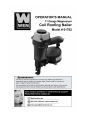
Technical Data
Magnesium Coil Roofing Nailer
Item 61782
Operating pressure range
70 psi-120 psi
Air inlet
1/4" NPT
Fastener length
7/8"-1 3/4"
Fastener diameter
0.120" (11 gauge)
Air consumption
0.1 cubic feet/cycle at 100 psi
Magazine capacity
120
Weight
5.58 lbs
Package Contents
1-Coil roofing nailer, 1-S3 Hex Wrench, 1-S4 Hex Wrench, 1-S5 Hex Wrench, 1- Oil, 1- Carrying Case,
1-Safety glasses, 1- Operator’s Manual
2 Fastener Specifications
Only use recommended fasteners. They may be screw, ring and smooth shank.
3 General Safety Rules
The purpose of safety symbols is to attract your attention to possible dangers. The safety symbols,
and the explanations with them, deserve your careful attention and understanding. The safety
warnings do not by themselves eliminate any danger. The instructions or warnings they give are
not substitutes for proper accident prevention measures.
Symbol Meaning
Safety Alert Symbol:
Indicated danger, warning, or caution, may be used in conjunction with other symbols or
pictographs. Always follow the safety precautions to reduce the risk of fire, electric
shock and personal injury.
NOTE: advising you of information or instructions is vital to the operation or maintenance of the
equipment.
Important
Servicing requires extreme care and knowledge and should be performed only by a qualified
service technician.
WARNING - Do not attempt to operate this tool until you have read thoroughly and
understand completely all instructions, safety rules, etc…contained in this manual.
Failure to comply can result in accidents involving fire, electric shock, or serious
personal injury. Save this operator’s manual and review frequently for continuing safe operation
and instructing others who may use this tool.
Safe operation of this power tool requires that you read and understand this operator’s manual and
all labels affixed to the tool. Safety is a combination of common sense, staying alert, and knowing
how your tool works.
“READ ALL INSTRUCTIONS” Failure to follow the safety rules listed below and other basic
safety precautions may result in serious personal injury.
•
•
•
•
Actuating tool may result in flying debris, collation material, or dust which could harm
operator’s eyes. Operator and others in work area MUST wear safety glasses with side shields.
These safety glasses must conform to ANSI Z87.1 requirements (approved glasses have “Z87”
printed or stamped on them). It is the employer’s responsibility to enforce the use of eye
protection equipment by the tool operator and other people in the work area.
Always wear appropriate personal hearing and other protection during use. Under some
conditions and duration of use, noise from this product may contribute to hearing loss.
Use only clean, dry, regulated air. Condensation from an air compressor can rust and damage
the internal workings of the tool.
Regulate air pressure. Use air pressure compatible with ratings on the spec label of the
tool. [Not to exceed 120 psi (8.3 bar)] Do not connect the tool to a compressor rated at over
175 psi. The tool operating pressure must never exceed 175 psi even in the event of regulator
failure.
4 General Safety Rules (Continued)
•
•
•
•
•
•
•
•
•
•
•
•
•
•
•
Only use air hose that is rated for a maximum working pressure of at least 150 psi (10.3
BAR) or 150% of the maximum system pressure, which ever is greater.
Do not use bottled gases to power this tool. Bottled compressed gases such as oxygen,
carbon dioxide, nitrogen, hydrogen, propane, acetylene or air are not for use with pneumatic
tools. Never use combustible gases or any other reactive gas as a power source for this tool.
Danger of explosion and/ or serious personal injury may result.
Use couplings that relieve all pressure from the tool when it is disconnected from the
power supply. Use hose connectors that shut off air supply from compressor when the tool is
disconnected.
Disconnect tool from air supply when not in use. Always disconnect tool from air supply
and remove fasteners from magazine before leaving the area or passing the tool to
another operator. Do not carry tool to another work area in which changing location
involves the use of scaffoldings, stairs, ladders, and the like, with air supply connected.
Do not make adjustments, remove magazine, and perform maintenance or clear jammed
fasteners while connected to the air supply. If the contact trip is adjusted when the tool is
connected to the air supply and nails are loaded, accidental discharge may occur.
Connect tool to air supply before loading fasteners to prevent a fastener from being fired
during connection. The tool driving mechanism may cycle when tool is connected to the air
supply. Do not load fasteners with trigger or safety depressed to prevent unintentional firing of
a fastener.
Do not remove, tamper with, or otherwise cause the tool, trigger, or contact trip to
become inoperable. Do not tape or tie trigger or contact trip in the on position. Do not remove
spring from contact trip. Make daily inspections for free movement of trigger and contact trip.
Uncontrolled discharge could result.
Inspect tool before use. Do not operate a tool if any portion of the tool, trigger, or contact
trip is inoperable, disconnected, altered, or not working properly. Leaking air, damaged
parts or missing parts should be repaired or replaced before use. Refer to Repairs.
Do not alter or modify the tool in any way.
Always assume that the tool contains fasteners.
Do not point the tool at co-workers or yourself at any time. No horseplay! Work safe!
Respect the tool as a working implement.
Keep bystanders, children, and visitors away while operating a power tool. Distractions
can cause you to lose control. When tool is not in use, it should be locked in a safe place, out of
the reach of children.
Remove finger from trigger when not driving fasteners. Never carry tool with finger on
trigger. Using the trigger lock-off will prevent accidental discharge. Accidental discharge
could result.
Do not overreach. Maintain proper footing and balance at all times. Loss of balance may
cause personal injury.
Make sure hose is free of obstructions or snags. Entangled or snarled hoses can cause loss of
balance or footing.
Use the tool only for its intended use. Do not discharge fasteners into open air, concrete,
stone, extremely hard woods, knots or any material too hard for the fastener to penetrate.
5 General Safety Rules (Continued)
•
•
•
•
•
•
•
•
•
•
•
Do not use the body of the tool or top cap as a hammer. Discharged fasteners may follow
unexpected path and cause injury.
Always keep fingers clear of contact trip to prevent injury from inadvertent release of
nails.
Refer to the Maintenance and Repairs for detailed information on the proper
maintenance of the tool.
Always operate the tool in a clean, lighted area. Be sure the work surface is clear of any
debris and be careful not to lose footing when working in elevated environments such as
rooftops.
Do not drive fasteners near edge of material. The workpiece may split causing the fastener
to ricochet, injuring you or a co-worker. Be aware that the nail may follow the grain of the
wood (shiner), causing it to protrude unexpectedly from the side of the work material. Drive
the nail perpendicular to the grain to reduce risk of injury.
Do not drive nails onto the heads of other fasteners or with the tool at too steep an angle.
Personal injury from strong recoil, jammed fasteners, or ricocheted nails may result.
Be aware of material thickness when using the nailer. A protruding nail may cause injury.
Be aware that when the tool is being utilized at pressures on the high end of its operating
range, nails can be driven completely through thin or very soft work material. Make sure
the pressure in the compressor is set so that nails are set into the material and not pushed
completely through.
Keep hands and body parts clear of immediate work area. Hold workpiece with clamps
when necessary to keep hands and body out of potential harm. Be sure the workpiece is
properly secured before pressing the nailer against the material. The contact trip may cause the
work material to shift unexpectedly.
Do not use tool in the presence of flammable dust, gases or fumes. The tool may produce a
spark that could ignite gases causing a fire. Driving a nail into another nail may also cause a
spark.
Keep face and body parts away from back of the tool cap when working in restricted
areas. Sudden recoil can result in impact to the body, especially when nailing into hard or
dense material.
Grip tool firmly to maintain control while allowing tool to recoil away from work surface
as fastener is driven. In bump action mode (contact actuation mode) if contact trip is allowed
to recontact work surface before trigger is released an unwanted fastener will be fired.
6 Specific Safety Rules for Coil Roofing Nailer
1. KEEP WORKING AREA CLEAN. Cluttered areas invite injuries.
2. DON’T ALLOW CHILDREN KEEP AT THE WORKING AREA. Don’t let them handle
the tool.
3. DO NOT OPERATE THIS TOOL IF UNDER THE INFLUENCE OF ALCOHOL OR
DRUGS. Read warning label on prescriptions to determine if your judgment or reflexes are
impaired while taking drugs. If there is any doubt, do not attempt to operate.
4. USE SAFETY GLASSES. Safety glasses should conform to ANSI Z87.1 specifications.
Before operating, wear safety glasses against flying debris from the front and side. Safety
glasses should be worn when loading, operating, unloading or servicing this tool.
5. USE EAR PROTECTION. The working area may be exposed to high noise levels that can
lead to hearing damaged.
6. NEVER USE OXYGEN COMBUSTIBLE GASES, BOTTLED GASES OR HIGH
PRESSURE COMPRESSED GAS AS A POWER SOURCE FOR THIS TOOL. The tool
may explode and cause serious injury.
7. DRESS SAFELY. Protective gloves and nonskid footwear or safety shoes are recommended
when working with and operating this tool. Don’t wear loose clothing or jewelry. They can get
caught in moving parts. Also, wear a protective hair covering to prevent long hair from getting
caught in the tool.
8. DO NOT FIRE TO HARD MATERIALS. Do not attempt to shoot toward hard or brittle
material such as concrete, steel or tile.
9. WHEN OPERATING TOOL. Keep the proper footing and balance to avoid damaged
resulting from losing balance.
10. CHECK DAMAGED PARTS. Before using tool, carefully check if there is any part damaged.
11. REPLACE PARTS AND ACCESSORIES. Only allow use same replacement parts while
servicing. Approved accessories and replacement parts are available.
12. KEEP ALERT. Watch what you are doing. Use common sense. Do not operate any tool when
you are tired.
13. STORE THE TOOL. When not in use, tool should be cleaned, fully assembled and then,
stored in a dry location to reduce rust. For safety, keep out of reach of children.
14. OUTDOORS EXTENSION CORDS. When air compressor is used outdoors, use only
rounded jackets extensions cords intended for outside use. See manufacturer’s manual for the
AWG required for the compressor’s amperage draw.
15. PAY ATTENTION TO AIR HOSE AND THEIR CONNECTIONS. Don’t trip over hoses.
Make sure all connections are tight.
16. AFTER LOADING THE FASTENERS. Never point the tool at yourself or bystanders.
7 Specific Safety Rules for Coil Roofing Nailer (Continued)
17. USE THE CORRECT AIR CONNECTOR. The connector on the tool must not hold
pressure when the air supply is disconnected. If the wrong fitting is used, the tool can be
charged with air after being disconnected and still be able to drive a fastener.
18. WHEN CONNECTING THE AIR. The tool can possibly fire the fasteners. Therefore,
remove all the fasteners before connecting to the air.
19. DO NOT DEPRESS THE SAFE BRACKET AND THE TRIGGER WHEN LOADING.
20. IF THE FASTENERS ARE JAMMED. Disconnect the tool from the air and remove the
jammed fasteners out.
WARNING: The warning, caution, and instructions explained in this instruction manual cannot
cover all possible conditions and situations that may occur. It must be understood by the operator
that COMMON SENSE AND CAUTION ARE FACTORS WHICH CANNOT BE BUILT INTO
THIS PRODUCT, BUT MUST BE SUPPLIED BY THE OPERATOR.
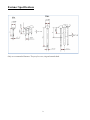
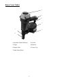
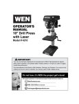
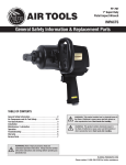
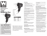
8 Know Your Nailer
1
2 3 4 7 5 6 1-Adjustable Exhaust Deflector
2-Air Inlet
3-Trigger
4-Magazine
5-Shingle Guide
6-Contact Trip
7-Depth Setting Wheel
9 Operation
WARNING - if any parts are missing, do not operate this tool until the missing parts are
replaced. Failure to do so could result in possible serious personal injury.
Lubrication
This tool requires lubrication before using the tool for the first time and before each use. If an
inline oiler is used, manual lubrication through the air inlet is not required.
Note: The work surface can become damaged by excessive lubrication. Proper lubrication is the
owner’s responsibility. Failure to lubrication the tool properly will dramatically shorten the life of
the tool and void your warranty.
1. Disconnect the air supply from the tool to add lubricant.
2. Turn the tool so the air inlet is facing up. Place 4-5 drops of 30W non-detergent oil (included)
into air inlet.
3. After adding oil, run toll briefly. Wipe off any excess oil from the exhaust.
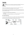
Recommended Hookup
Your air tool is fully assembly when you receive it. Before using it, attach the air line and desired
air system accessories. See below for the recommended accessories and connection order. Be sure
the air hose is depressurized when installing or removing adapters to the air line.
10 Operation (Continued)
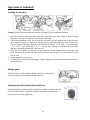
Loading the fasteners
Caution: Always disconnect the tool from the air supply before loading the fasteners.
1. Open the magazine. Pull down door latch and swing door open. Door swing to the left. Swing
magazine cover open. Magazine cover swings to the right.
2. Check the adjustment for the size of nail to be inserted. The nail support can be moved up or
down to three settings. To change the setting, pull up on the post and twist to the correct stop.
The nail support should be adjusted to the position as follows: 1-3/4" nails – use bottom stop;
1-1/4", 1-1/2" – use middle stop; 7/8", 1" – use top stop. A gauge is located on the side of the
magazine noting the position for each size nail.
3. Place the coil of nails over the post in the magazine. Uncoil enough nails to reach the feed
pawl, and place the second nail between the teeth on the feed pawl. The nail heads fit in the
slot on nose.
4. Swing magazine cover closed.
5. Close the door, check the latch engages. (If not engaging, check that the nail heads are in the
slot on the noses.
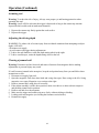
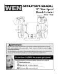
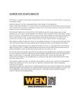
Shingle guide
This guide can be used to control shingle spacing. Loosen the two
screws to adjust gauge to desired shingle exposure.
Adjusting the directional exhaust deflector
Adjust directional exhaust deflector. So that the exhaust air blast is directed
away from the operator. Grasp the deflector and rotate it to the desired
position for the current application.
11 Operation (Continued)
Actuating tool
Warning: To reduce the risk of injury, Always wear proper eye and hearing protection when
operating this tool.
Warning: A nail will fire each time the trigger is depressed as long as the contact trip remains
depressed which could result in inadvertent actuation.
1. Depress the contact trip firmly against the work surface.
2. Depress the trigger.
Adjusting the driving depth
WARNING: To reduce risk of serious injury from accidental actuation when attempting to adjust
depth, ALWAYS:
• Disconnect air supply.
• Avoid contact with trigger during adjustments.
1. To drive the nail shallower, rotate the depth setting wheel to the right.
2. To drive a nail deeper, rotate the depth setting wheel to the left.
Clearing a jammed nail
Warning: Disconnect air line from tool and remove fasteners from magazine before making
adjustments or personal injury may result.
If a nail becomes jammed in the nosepiece, keep the tool pointed away from you and follow these
instructions to clear:
1. Disconnect air supply from tool.
2. Open the magazine. Pull down door latch and swing door open. Door swing to the left. Swing
magazine cover open. Magazine cover swings to the right.
3. Remove jammed nail, using pliers if necessary.
4. If the piston assembly is in the down position, insert screwdriver or other rod into nosepiece
and push the piston back in position.
5. Remove rod and close the magazine.
6. Make sure the trigger and contact trip move freely without sticking or binding.
7. Loading nails into magazine (see loading the fasteners section before).
8. Reattach air supply.
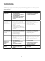
12 Troubleshooting
Caution: Stop using the tool immediately if any of the following problems occur. Serious personal
injury could occur.
Problem
Air leaking at
Trigger area
Cause
1. O-ring in trigger valve stem is
worn and damaged.
2. O-ring in trigger valve head is
worn and damaged.
3. Foreign matter is preventing the
trigger from moving to OFF
position.
Solution
1. Check/replace O-ring/lubricate.
2. Check/replace O-ring/lubricate.
3. Clean the tool/lubricate.
Air leaking at the
body. lower
portion and nose
1. Screw is loose at connecting
portion of the nose and body.
2. O-ring is damaged between body
and nose
3. Bumper is damaged.
4. Foreign matter is lodged at the
contacting portion of the bumper
and body.
1.
2.
3.
4.
Air leaking at the
body upper portion
and nose
1. Screw is loose at the connecting
portion of the cylinder and body.
2. O-ring is damaged.
3. Gasket is damaged.
1. Tighten the screw and recheck.
2. Check/replace O-ring/lubricate.
3. Replace the gasket.
Failure to start tool
1. Tool dry, lack lubrication.
2. The spring in the cylinder cap is
damaged.
3. Valve sticks with cylinder cap.
4. No compressed air.
1. Safe bracket position is not
correct.
2. Air pressure is too high.
1. Use pneumatic tool oil.
2. Replace the spring in the cylinder
cap.
3. Disassemble/check/lubricate.
4. Check air supply.
Blade driving
fasteners too
deeply
Fasteners are
jammed.
1. Fasteners are wrong size.
2. Weld wires in nail coil are
broken.
13 Tighten screw/recheck.
Check/replace O-ring/lubricate.
Replace the bumper.
Disassemble and clean.
1. Rotate knob of the adjuster to
move safe bracket down.
2. Decrease air pressure.
1. Use recommended fasteners.
2. Stop using.
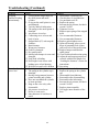
Troubleshooting (Continued)
Problem
Skipping
fasteners/feeding
intermittently
Runs slowly or has
power loss
Cause
1. Foreign matter lodged between
the small piston and small
cylinder.
2. O-ring on the small piston is worn
and damaged.
3. Tool dry and lack lubrication.
4. The spring on the small piston is
damaged.
5. Air pressure is too low.
6. Connecting screw of nose and
body is loose.
7. Stopped hook (87) can't stop the
fasteners.
8. Bent fasteners.
9. Wrong size fasteners.
10. Gasket is damaged.
11. Dry small piston.
12. Small piston bumper is worm and
damaged.
13. Feed hook is binding.
14. Nail length is not correct with
loading space of nail housing.
15. Weld wires in nail coil is broken.
1. Tool dry, lack lubrication.
2. The spring in the cylinder cap is
damaged.
3. Having foreign matters between
piston assembly and cylinder.
4. Have not assembled the cylinder
to home position.
5. Ring on the valve is dry after
disassemble.
6. Air pressure is too lower.
7. Driver is worn (sort).
8. Inner diameter of used hose is
small.
14 Solution
1. Disassemble/ clean/lubricate.
2. Check/replace O-ring/lubricate.
3. Use pneumatic tool oil.
4. Replace the spring.
5. Increase the air pressure, but don't
exceed 120 PSI.
6. Tighten al l screw.
7. Replace taper spring of the stopped
hook.
8. Use recommended fasteners.
9. Use recommended fasteners.
10. Replace gasket/tighten screw.
11. Open nail housing, place several
drops of pneumatic tool oil into
end cover hole of the small piston.
12. Replace bumper and lubricate
small piston.
13. Clean feed hook and torsion spring
14. Adjust the nail support position to
coincide with the nail length. See
“Loading the fasteners” section for
instructions.
15. Stop using.
1. Use pneumatic tool oil.
2. Replace the spring in the cylinder
cap.
3. Disassemble/clean/lubricate.
4. Reassemble after disassembling.
5. Reassemble after lubricating.
6. Increase the air pressure, but don't
exceed 120 PSI.
7. Replace piston assembly.
8. Use bigger inner diameter of the
hose.
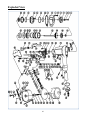
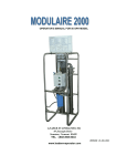
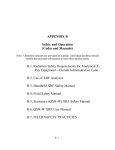
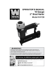
Exploded View
15 Parts List
Item#
1
2
3
4
5
6
7
8
9
10
11
12
13
14
15
16
17
18
19
20
21
22
22a
22b
23
24
25
26
27
28
29
30
31
32
33
34
35
36
37
38
39
40
41
42
43
44
44a
45
Stock #
61782-001
61782-002
61782-003
61782-004
61782-005
61782-006
61782-007
61782-008
61782-009
61782-010
61782-011
61782-012
61782-013
61782-014
61782-015
61782-016
61782-017
61782-018
61782-019
61782-020
61782-021
61782-022
61782-022a
61782-022b
61782-023
61782-024
61782-025
61782-026
61782-027
61782-028
61782-029
61782-030
61782-031
61782-032
61782-033
61782-034
61782-035
61782-036
61782-037
61782-038
61782-039
61782-040
61782-041
61782-042
61782-043
61782-044
61782-044a
61782-045
Description
Screw
Spring Washer
Bushing
Exhaust Cover
Washer
Screw
Spring Washer
Cylinder Cap
Gasket
O-ring 36.3x2.5
O-ring 54.3x3
Spring
Valve
O-ring 40.2x2.3
Valve Seal
Valve Seat
Stopped Washer
Washer
O-ring 43.3x3.5
Piston Assembly
Cylinder
O-ring 50.5x2.5
Restrictive Plate
O-ring 70.4x3.5
Cylinder Seal
Bumper
Protective Piece
Soft Spacer
Body
O-ring 46x1.3
Restrictive Washer
O-ring 8.3x1.8
Nose
Screw
Bracket
Spring
Adjuster
Bracket Assembly
Spring Pin
Safe Bracket Guide
Trigger Valve Guide
O-ring 12.8x1.9
O-ring 14.3x1.9
O-ring 6.4x1.5
Trigger Valve Stem
Trigger Valve Guide
Bushing
O-ring 12.3x1.9
Item#
46
47
48
49
50
51
52
53
54
55
56
57
58
59
60
61
62
63
64
65
66
67
68
69
70
71
72
73
74
75
76
77
78
79
80
81
82
83
84
85
86
87
88
89
90
91
92
93
16 Stock #
61782-046
61782-047
61782-048
61782-049
61782-050
61782-051
61782-052
61782-053
61782-054
61782-055
61782-056
61782-057
61782-058
61782-059
61782-060
61782-061
61782-062
61782-063
61782-064
61782-065
61782-066
61782-067
61782-068
61782-069
61782-070
61782-071
61782-072
61782-073
61782-074
61782-075
61782-076
61782-077
61782-078
61782-079
61782-080
61782-081
61782-082
61782-083
61782-084
61782-085
61782-086
61782-087
61782-088
61782-089
61782-090
61782-091
61782-092
61782-093
Description
Washer
Trigger
Trigger Spring
Spring Pin
Feed Hook
Washer
Feed Hook Pin
Torsion Spring
Piston
O-ring 24.3x2.8
Piston Bumper
Spring
Cover
Locking Washer
Screw
Spring Pin
Handle
Washer
Latch
Pin
Protector
Spring
Shaft
Pin
Stopped Hook
Taper Spring
Block Plate
Spring Washer
Screw
Nut
Washer
Connected Plate
Support
Bracket
Screw
Screw
Lower Nail Housing
Pin
Adjuster Bushing
Adjuster Stem
Adjuster Plate
Spring Pin
Adjuster Nut
Upper Nail Housing
Soft Grip Sleeve
O-ring 48.5x2.5
End Cap
Air Plug
Limited One Year Warranty
WEN Products is committed to build tools that are dependable for years. Our warranties are consistent with this commitment and
our dedication to quality
LIMITED WARRANTY OF WEN CONSUMER POWER TOOLS PRODUCTS FOR HOME USE
GREAT LAKES TECHNOLOGIES, LLC ("Seller") warrants to the original purchaser only, that all WEN consumer power tools
will be free from defects in material or workmanship for a period of one (1) year from date of purchase. Ninety (90) days for all
WEN products, if the tool is used for professional use.
SELLER'S SOLE OBLIGATION AND YOUR EXCLUSIVE REMEDY under this Limited Warranty and, to the extent permitted
by law, any warranty or condition implied by law, shall be the repair or replacement of parts, without charge, which are defective in
material or workmanship and which have not been misused, carelessly handled, or misrepaired by persons other than Seller or
Authorized Service Center. To make a claim under this Limited Warranty, please contact us at 1-800-232-1195 or write to us at
WEN Products, 501 Davis Road, Elgin, IL 60123. To acquire service, you will have to provide proof of purchase and may be asked
to ship the tool back to us freight prepaid.
THIS LIMITED WARRANTY DOES NOT APPLY TO ACCESSORY ITEMS SUCH AS CIRCULAR SAW BLADES, DRILL
BITS, ROUTER BITS, JIGSAW BLADES, SANDING BELTS, GRINDING WHEELS AND OTHER RELATED ITEMS.
ANY IMPLIED WARRANTIES SHALL BE LIMITED IN DURATION TO ONE (1) YEAR FROM DATE OF PURCHASE.
SOME STATES IN THE U.S., SOME CANADIAN PROVINCES DO NOT ALLOW LIMITATIONS ON HOW LONG AN
IMPLIED WARRANTY LASTS, SO THE ABOVE LIMITATION MAY NOT APPLY TO YOU.
IN NO EVENT SHALL SELLER BE LIABLE FOR ANY INCIDENTAL OR CONSEQUENTIAL DAMAGES (INCLUDING
BUT NOT LIMITED TO LIABILITY FOR LOSS OF PROFITS) ARISING FROM THE SALE OR USE OF THIS PRODUCT.
SOME STATES IN THE U.S. AND SOME CANADIAN PROVINCES DO NOT ALLOW THE EXCLUSION OR LIMITATION
OF INCIDENTAL OR CONSEQUENTIAL DAMAGES, SO THE ABOVE LIMITATION OR EXCLUSION MAY NOT APPLY
TO YOU.
THIS LIMITED WARRANTY GIVES YOU SPECIFIC LEGAL RIGHTS, AND YOU MAY ALSO HAVE OTHER RIGHTS
WHICH VARY FROM STATE TO STATE IN THE U.S., PROVINCE TO PROVINCE IN CANADA AND FROM COUNTRY
TO COUNTRY.
THIS LIMITED WARRANTY APPLIES ONLY TO PORTABLE ELECTRIC TOOLS, BENCH POWER TOOLS, OUTDOOR
POWER EQUIPMENT AND PNUMATIC TOOLS SOLD WITHIN THE UNITED STATES OF AMERICA, CANADA AND
THE COMMONWEALTH OF PUERTO RICO. FOR WARRANTY COVERAGE WITHIN OTHER COUNTRIES, CONTACT
THE WEN CUSTOMER SUPPORT.
17