1
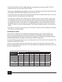
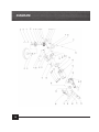
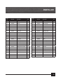
OPERATOR’S MANUAL
7" Variable Speed
Polisher/Sander
Model # 946
Important:
Your new tool has been engineered and manufactured to WEN’s® high standards for dependability, ease of operation, and operator safety. Properly cared for, it will give you years of rugged,
trouble-free performance.
Pay close attention to the Rules for Safe Operation, Warnings, and Cautions. If you use your tool
properly and only for what it is intended, you will enjoy years of safe, reliable service.
We Got Your Back
It's not how, it's WEN the project get's done!
Got product questions or need technical support? Please feel free to contact us!
WenProducts.com
800- 232-1195 M–F 8-5 CST
[email protected]
Table Of Contents
SECTION
PAGE
Specifications . . . . . . . . . . . . . . . . . . . . . . . . . . . . . . . . . . . . . . . . . . . . . . . . . . . . . . . 3
Rules for Safe Operation . . . . . . . . . . . . . . . . . . . . . . . . . . . . . . . . . . . . . . . . . . . 4
General Instructions for All Power Tools . . . . . . . . . . . . . . . . . . . . . . . 5–8
Extension Cords . . . . . . . . . . . . . . . . . . . . . . . . . . . . . . . . . . . . . . . . . . . . . . . . . . . . 8
Know Your Tool . . . . . . . . . . . . . . . . . . . . . . . . . . . . . . . . . . . . . . . . . . . . . . . . . . . . . 9
Unpacking & Assembly Instruction . . . . . . . . . . . . . . . . . . . . . . . . . . . . . . . 9–10
Operation . . . . . . . . . . . . . . . . . . . . . . . . . . . . . . . . . . . . . . . . . . . . . . . . . . . . . . . . . . 11
Maintenance . . . . . . . . . . . . . . . . . . . . . . . . . . . . . . . . . . . . . . . . . . . . . . . . . . . . . . . 13
Diagram & Parts list . . . . . . . . . . . . . . . . . . . . . . . . . . . . . . . . . . . . . . . . . . . . . 14–15
Warranty . . . . . . . . . . . . . . . . . . . . . . . . . . . . . . . . . . . . . . . . . . . . . . . . . . . . . . . . . . 16
2
7" Variable Speed Polisher/Sander
SPECIFICATIONS
Model Number:
946
Motor:
120V~60Hz, AC only
Input:
11 AMPS
Speed
600-3,000 RPM
Pad Size:
Arbor Size:
Weight:
7"
5/8"-11
8 lbs. 6oz.
Package Contents:
• 1-7" Variable Speed Polisher/Sander
• 1-7" Hook & Loop Backer Pad
• 1-Foam Applicator Pad
• 1-Terry Cloth Bonnet
• 1-Sanding Disc
• 1-Side Handle
3
Rules For Safe Operation
The purpose of safety symbols is to attract your attention to possible dangers. The safety symbols,
and the explanations with them, deserve your careful attention and understanding. The safety
warnings do not by themselves eliminate any danger. The instructions or warnings they give are
not substitutes for proper accident prevention measures.
Symbol Meaning
Safety Alert Symbol:
Indicated danger, warning, or caution, may be used in conjunction with other symbols
or pictographs. Always follow the safety precautions to reduce the risk of fire, electric
shock and personal injury.
NOTE: Advising you of information or instructions is vital to the operation or maintenance of the
equipment
IMPORTANT
Servicing requires extreme care and knowledge and should be performed only by a qualified
service technician. For service, we suggest you return the tool to WEN PRODUCTS a division of
Great Lakes Technologies, LLC. for repair. When servicing, use only identical WEN® replacement
parts.
WARNING - Do not attempt to operate this tool until you have read thoroughly
and understand completely all instructions, safety rules, etc…contained in this
manual. Failure to comply can result in accidents involving fire, electric shock,
or serious personal injury. Save this operator’s manual and review frequently for
continuing safe operation and instructing others who may use this tool.
Safe operation of this power tool requires that you read and understand this operator’s manual and
all labels affixed to the tool. Safety is a combination of common sense, staying alert, and knowing
how your tool works.
4
General Instructions for all Power Tools
READ ALL INSTRUCTIONS!!!
• Know your power tool. Read the operator’s manual carefully. Learn the application and
limitations as well as specific potential hazards related to this tool.
• Keep guards in place and in working order. Never operate the tool with any guard or cover
removed. Make sure all guards are operating properly before each use.
•Remove adjusting keys & wrenches. Form a habit of checking to see keys and adjusting
wrenches are removed from tool before turning it on.
• Keep work area clean. Cluttered work areas and work benches invite accidents.
• Do not use in dangerous environments. Do not use power tools near gasoline or other flammable
liquids, in damp or wet locations or expose them to rain. Keep work area well lighted.
• Keep children and visitors away. All visitors should wear ANSI-Z87.1 approved safety glasses and
be kept a safe distance from work area.
• Make workshop childproof with padlocks, master switches, or by removing starter keys.
• Don’t force the tool. It will do the job better and safer at the rate for which it was designed.
• Use the right tool. Do not force the tool or attachment to do a job for which it was not designed.
• Wear proper apparel. Do not wear loose clothing, neckties, or jewelry that can get caught in the
tool’s moving parts and cause personal injury. Non-slip footwear is recommended when working
outdoors. Wear protective hair covering to contain long hair.
• Always wear ANSI-Z87.1 approved safety glasses with side shields. Everyday eyeglasses have
only impact-resistant lenses; they are NOT safety glasses.
• Secure work. Use clamps or a vise to hold work when practical. It’s safer than using your hand
and it frees both hands to operate the tool.
• Do not overreach. Keep proper footing and balance at all times.
• Maintain tools with care. Keep tools sharp and clean for best and safest performance. Follow
instructions for lubricating and changing accessories.
• Disconnect all tools. When not in use, before servicing, or when changing attachments, blades,
bits, cutters, etc…, all tools should be disconnected from power source.
• Reduce the risk of unintentional starting. Be sure switch is off when plugging in.
5
• Use recommended accessories. Consult the operator’s manual for recommended accessories.
The use of improper accessories may cause risk of injury.
•Never stand on tool. Serious injury could occur if the tool is tipped or if the blade is unintentionally
contacted.
•Direction of feed. Feed work into a blade or cutter against the direction or rotation of the blade or
cutter only.
• Never leave tool running unattended. Turn power off. Don’t leave tool until it comes to a complete
stop.
• Check damaged parts. Before further use of the tool, a guard or other part that is damaged should
be carefully checked to determine that it will operate properly and perform its intended function.
Check for alignment of moving parts, binding or moving parts, breakage of parts, mounting and
any other condition that may affect its operation. A guard or other part that is damaged must be
properly repaired or replaced by an authorized service center to avoid risk of personal injury.
• Protect your hearing. Wear hearing protection during extended periods of operation.
• Keep tools dry, clean, and free from oil and grease. Always use a clean cloth when cleaning.
Never use brake fluids, gasoline, petroleum-based products, or any solvents to clean tool.
• PROTECT YOUR LUNGS. Wear a face or dust mask if the operation is dusty.
WARNING - Some dust created by power sanding, sawing, grinding, drilling,
and other construction activities contains chemicals known to cause cancer, birth
defects or other reproductive harm. Some examples of these chemicals are:
• Lead from lead-based paints
• Crystalline silica from bricks and cement and other masonry products
• Arsenic and chromium from chemically treated lumber. Your risk from these
exposures varies, depending on how often you do this type of work. To reduce
your exposure to these chemicals, work in a well ventilated area, and work with
approved safety equipment, such as those dust masks that are specially
designed to filter out microscopic particles.
• Guard against electrical shock by preventing body contacting with grounded surfaces. For
example: pipes, radiators, ranges, refrigerator enclosures.
• Inspect tool cords and extension cords periodically and, if damaged, have repaired by a
qualified service technician. Stay constantly aware of cord location and keep it away from the
rotating wheel.
6
• Never use in an explosive atmosphere. Normal sparking of the motor could ignite fumes.
• Use only outdoor extension cords with approved ground connection that are intended for use
outdoors and so marked.
• Avoid awkward operations and hand positions where a sudden slip could cause your hand to
move into the blade. ALWAYS make sure you have good balance.
• Allow the motor to come up to full speed before starting a cut to avoid binding or stalling
• Do not use tool if switch does not turn it on and off. Have defective switches replaced by an
authorized service center.
• Replacement parts. All repairs, whether electrical or mechanical, should be made by a qualified
service technician at an authorized service center.
WARNING - when servicing use only identical WEN® replacement parts. Use
of any other part may create a hazard or cause product damage.
• Keep hands away from cutting area. Do not hand hold pieces so small that your fingers go under
the blade guard. Do not reach underneath work or in blade cutting path with your hands and
fingers for any reason.
• Before making a cut, be sure all adjustments are secure.
• Always support large work pieces while cutting to minimize risk of blade pinching and kickback.
Tool may slip, walk or slide while cutting large or heavy boards.
• Do not remove jammed cutoff pieces until blade has stopped.
• Never start the tool when the blade is in contact with the work piece.
• Never touch blade or other moving parts during use.
• Before changing the setup, removing covers, guards or blades, unplug the tool and remove the
switch key.
• Always turn off tool before disconnecting it to avoid accidental starting when reconnecting to a
power source.
WARNING - DO NOT OPERATE THIS TOOL WHILE UNDER THE
INFLUENCE OF DRUGS, ALCOHOL OR ANY MEDICATION THAT MAY
IMPAIR YOUR JUDGMENT OR CONTROL!
7
• Stay alert and exercise control. Watch what you are doing and use common sense. DO NOT
operate tool when you are tired. DO NOT RUSH!
• Make sure work area has ample lighting to see the work and that no obstructions will interfere with
safe operation BEFORE performing any work by using your tool.
• Save these instructions. Refer to them frequently and use them to instruct other users. If you loan
someone this tool, loan them these instructions also.
• Use the proper extension cord. Make sure your extension cord is in good condition. When using
an extension cord, be sure to use one heavy enough to carry the current your product will draw.
An undersized cord will cause a drop in line voltage resulting in loss of power and overheating. A
wire gauge size (A.W.G.) of at least 16 is recommended for an extension cord 25 feet or less in
length. If in doubt, use the next heavier gauge. The smaller the gauge number is, the heavier the
cord is.
• Don’t abuse cord. Never carry tool by the cord or yank it to disconnect from receptacle. Keep cord
from heat, oil, and sharp edges.
EXTENSION CORDS
In the event of a malfunction or breakdown, grounding provides a path or least resistance for
electric current and reduces the risk of electrical shock. Tools equipped with an electrical cord
having an equipment-grounding conductor must be plugged into a matching outlet that is properly
installed and grounded in accordance with all local codes and ordinances.
Do not modify the plug provided in any way. If the plug does not fit the outlet, have the proper outlet
installed by a qualified electrician.
The use of any extension cord will cause some loss of power. To keep this to a minimum and to
prevent overheating and motor burned-out; use the table below to determine the minimum wire size
(A.W.G.) of extension cord.
Recommended Minimum Wire Gauge for Extension Cords (120 Volt)
Nameplate Amperes
(At Full Load)
8
Extension Cord Length
25 Feet
50 Feet
75 Feet
100 Feet
150 Feet
200 Feet
0–2.0
18
18
18
18
16
16
2.1–3.4
18
18
18
16
14
14
3.5–5.0
18
18
16
14
12
12
5.1 –7.0
18
16
14
12
12
10
7.1–12.0
18
14
12
10
8
8
12.1–16.0
14
12
10
10
8
6
16.1–20.0
12
10
8
8
6
6
Know Your Tool
➍
➌
➎
➋
➊
➏
➐
➑
➒
➓
1
2
3
4
5
6
7
8
9
10
Gear Housing
Spindle Lock
Motor Housing
Variable Speed Dial
Lock-On Button
Trigger ON/OFF Switch
Brush Cap
Side Handle
Hook and Loop Pad Backer
7" Terry Cloth Bonnet & Foam
Applicator Pad (underneath)
UNPACKING
WARNING - to prevent accidental starting that could cause possible serious
personal injury, assemble all parts to your polisher/sander before connecting it to
power supply. Polisher/Sander should never be connected to power supply when
you are assembling parts, making adjustments, installing or removing bonnets,
or when not in use.
WARNING - if any parts are missing, do not operate this tool until the missing
parts are replaced. Failure to do so could result in possible serious personal injury.
9
• Do not discard the packing materials until you have carefully inspected the tool, identified all parts,
and satisfactorily operated your new tool.
NOTE: if any parts are damaged or missing, do not attempt to plug in the power cord and turn the
switch on until the damaged or missing parts are obtained and are installed correctly.
Assembly Instruction
INSTALLING SIDE HANDLE
A side handle is included with your sander/polisher to ease tool handling and to help maintain tool
control during operation. The gear housing is designed to allow mounting of the side handle on
either side of the tool.
To install the side handle, screw the handle securely into the threaded hole on the right or left, of the
gear housing as desired.
SPINDLE LOCK BUTTON
A spindle lock button has been provided for locking the spindle of your tool in a stationary position.
Depress and hold the lock button while installing, changing, or removing accessories.
HOOK & LOOP BACKER PAD INSTALLATION/REMOVAL
1. Unplug the sander/polisher from the power source. Failure to unplug the sander/polisher from the
power source may result in accidental tool start-up, causing possible serious personal injury.
2. P
lace the tool on a flat, stable surface, with the threaded spindle facing upwards and slide the
rubberbacker pad over and down the spindle, flat face up. Screw on the backer pad by rotating it
in a clockwise direction.
3. Depress the spindle lock button, and then rotate backer pad clockwise until the spindle lock engages the spindle shaft so it will no longer rotate.
4. Maintain pressure on the spindle lock, preventing the spindle shaft from rotating. Tighten the
backer pad by hand rotating the pad until snug. DO NOT OVER TIGHTEN.
5. Release the spindle lock button.
6. To remove the rubber backing back, be sure the tool is unplugged from the power source,
engage the spindle lock and perform the installation procedure in reverse order.
FOAM APPLICATOR PAD INSTALLATION/REMOVAL
1. Unplug the sander/polisher and install the rubber backer pad as explained previously.
2. Inspect the hook & loop backER pad and clean-off any dirt or debris that is discovered.
3. Align the foam applicator pad over the backer pad. With the pad aligned, push down on the foam
applicator pad to engage the hook & loop system. Confirm that the polishing pad is secured over
the entire pad.
4. To remove the foam applicator pad, pull it off the backer pad.
ABRASIVE DISC REMOVAL/INSTALLATION
1. Unplug the sander/polisher from the power source. Failure to unplug the sander/polisher from the
power source may result in accidental tool start-up, causing possible serious personal injury.
2. Install the backer pad onto the sander/polisher threaded spindle as described earlier.
3. Center the desire hook & loop grit abrasive disc over the backer pad.
4. W
ith the disc aligned, push down on the disc to engage the hook & loop system.
Confirm that the disc is secured over the entire pad.
5. To remove the disc, pull it off the backer pad.
10
OPERATION
Always be sure the tool is switched off and unplugged before assembling parts, making adjustments, assembling or replacing sanding discs, buffer pads, or checking function on the tool.
SPINDLE LOCK
Never depress the spindle lock button when the spindle is moving.
The spindle lock button is located on the top, forward portion of the gear housing. Depress the
spindle lock button to prevent the spindle from rotating when installing or removing accessories.
SWITCH OPERATION
The tool can be locked on by depressing the lock-on button and the on/off switch at the same time,
then releasing pressure on the on/off switch. The lock-on feature is to relieve fatigue on the trigger
finger only. Grip tool firmly at all times while it is running, and keep both hands away from the Sanding/Polishing wheel.
SPEED ADJUSTMENT DIAL
The speed adjustment dial is located on top of the rear handle. In this position slightly forward of the
switch trigger, the sander/polisher’s speed is easily adjusted by the operator’s thumb on the hand
grasping the tool on the rear handle.
With the switch trigger fully depressed and the tool running, tool speed can be changed by rotating the speed adjustment dial to a numbered setting from 1 to 6. Tool speed increases as the dial is
moved in the direction of the number 6 and lower speed is obtained as the dial is turned towards the
number 1. To ensure operator control, the tool should always be turned “ON” with the speed adjustment dial in the number 1 position.
Continuous operation of the tool at low speeds for a long time will cause the motor to become
overheated, possibly resulting in malfunction or tool failure. To cool the motor, occasionally run the
tool at high RPM under no load for short periods of time allowing the tool’s fan to cool the motor. Be
careful not to obstruct the air vents located in the forward gear housing or in the rear handle, near
the switch trigger.
The speed adjustment dial can only be rotated as far back as the number 1 or forward to the
number 6. DO NOT attempt forcing the dial beyond the numbers 1 or 6, or the speed adjustment
dial will be damaged and no longer function.
POLISHING OPERATION
Always wear safety glasses with side shields or a full face shield during tool operation.
Never switch on the tool when it is contacting the work piece or possible injury to the operator or
damaging the work piece may occur.
Hold the tool firmly using both handles. With the speed adjustment dial set at “1” turn the tool on
and lightly apply the rotating foam pad to the work surface. Allow the tool to operate freely using
only the tool’s weight as pressure applied to the work surface.
Maintain the foam pad at a angle of about 15 degrees to the work surface. NEVER USE THE POLISHING PAD FLAT TO THE WORK SURFACE. Use a long sweeping motion, back and forth, while
slowly advancing along the surface being polished. To avoid “burning” the surface or causing finish
swirls, use a low speed and do not hold the tool in one spot or use circular or spiral like patterns.
11
Work from the highest point on the surface downwards to avoid dust or polish from being thrown
onto the completed section.
Always follow the wax and polish manufacturer’s application and removal instructions for power
polishers. Dirty or clogged pads may be cleaned by washing in warm water with a mild detergent.
Allow the cleaned pad to dry completely before reuse.
SANDING OPERATION
Always wear safety glasses with side shields or a full face shield during tool operation.
The tool and sanding disc must completely stop rotating before setting the tool down after use onto
a workbench or other surface.
Always maintain a firm grip on the tool with both hands at all times. Not doing so may cause the
operator to lose control of the tool and may lead to serious personal injury.
Be sure the work piece is firmly clamped or otherwise secured in place. Remove any objects that
may struck and thrown by the rotating abrasive discs. If using an extension cord, be sure it is held
away from the work area.
Hold the tool firmly using both handles. With the speed adjustment dial set at “1” turn the tool on
and lightly apply the abrasive disc to the work piece. Never use the sanding disc flat on the work
surface, keep the abrasive disc at an angle of about 15 degrees while working the work piece surface.
Adjust the tool's speed using the speed adjustment dial as you become more familiar with the tool’s
operation and the amount of work being performed by the chosen grit abrasive disc. Use working
motions as described in the earlier “Polishing” instructions. Do not allow the abrasive disc to sand in
one spot too long or an uneven or gouged surface may result.
When the sanding operation is completed, remove the tool from the work surface before turning
it off.
12
MAINTENANCE
GENERAL
•S
ome important part of the double insulation system should be serviced only by a qualified service technician.
• Avoid using solvents when cleaning plastic parts. Most plastics are susceptible to various types
of commercial solvents and may be damaged by their use. Use clean cloth to remove dirt, carbon
dust, etc.
WARNING - Do not at any time let brake fluid; gasoline, petroleum based
products, penetrating oils, etc. come in contact with plastic parts. The contain
chemicals that can damaged, weaken, or destroy plastic.
LUBRICATION
• All of the bearings in this tool are lubricated with a sufficient amount of high grade lubricant for
the life of the unit under normal operating conditions. Therefore, no further lubrication is required.
•W
hen electric tools are used on fiberglass boats, sports cars, wallboard, sparkling compounds,
or plaster, it has been found that they are subject to accelerated wear and possible premature
failure, as the fiberglass chips and grindings are highly abrasive to bearings, brushes, commutator, etc. Consequently, it is not recommended that this tool be used for extended work on any
fiberglass material, wallboard, sparkling compounds, or plaster. During any use on fiberglass, it is
extremely important that the tool is cleaned frequently by blowing with an air jet.
WARNING - Always wear safety goggles or safety glasses with side shields
during power tool operation or when blowing dust. If operation is dusty also wear
a dust mask.
13
DIAGRAM
14
Parts List
Item
No.
Stock No.
Description
Qty.
Item
No.
Stock No.
Description
1
946-001
Spindle Lock Button
1
24
946-024
Lead Wind Ring
1
2
3
946-002
Lock Pin
1
25
946-025
Motor Housing
1
946-003
Spring
1
26
946-026
Stator
1
4
946-004
Washer Ø 5. 6x0.6
1
27
946-027
Tapping Screw ST4.2x68
2
5
946-005
Gear Housing
1
28
946-028
Washer
4
6
946-006
Oil Bearing
1
29
946-029
Right Handle Base
1
7
946-007
Driven Gear
1
30
946-030
Left Handle Base
1
8
946-008
Washer Ø30. 1x1.2
1
31
946-031
Tapping Screw ST4. 2x22
4
9
946-009
Bearing 6001
1
32
946-032
Carbon Brush Hold
2
10
946-010
Gear Base
1
33
946-033
Carbon Brush Assembly
2
11
946-011
Dust Proof Washer
1
34
946-034
Carbon Brush Cap
2
12
946-012
Arbor Shaft
1
35
946-035
Switch
1
Qty.
13
946-013
Hoop & Loop Backer Pad
1
36
946-036
Variable Speed Knob
1
13a
946-013a
Foam Applicator Pad
1
37
946-037
Identical Power Set
1
14
946-014
Screw
4
38
946-038
Power Cord
1
15
946-015
Washer
4
39
946-039
Cord Sleeve
1
16
946-016
Tapping Screw ST4.2x30
4
40
946-040
Cord Clip
1
17
946-017
Side Handle
1
41
946-041
Tapping Screw
2
18
946-018
Bearing 6001
1
42
946-042
Tapping Screw
2
19
946-019
Bearing Clip
1
43
946-043
Rubber Protector Cap
2
20
946-020
Screw
4
44
946-044
Screw M4x12
2
21
946-021
Rotor
1
45
946-045
Rubber Protector
2
22
946-022
Bearing 608
1
46
946-046
Handle Cover
1
23
946-023
Decouple Ring
1
15
WARRANTY
Warranty
WEN Products is committed to build tools that are dependable for years. Our warranties are consistent
with this commitment and our dedication to quality
LIMITED WARRANTY OF WEN CONSUMER POWER TOOLS PRODUCTS FOR HOME USE
GREAT LAKES TECHNOLOGIES, LLC ("Seller") warrants to the original purchaser only, that all WEN
consumer power tools will be free from defects in material or workmanship for a period of one year from
date of purchase. Ninety days for all WEN products, if the tool is used for professional use.
SELLER'S SOLE OBLIGATION AND YOUR EXCLUSIVE REMEDY under this Limited Warranty and, to the
extent permitted by law, any warranty or condition implied by law, shall be the repair or replacement of parts,
without charge, which are defective in material or workmanship and which have not been misused, carelessly
handled, or misrepaired by persons other than Seller or Authorized Service Center. To make a claim under
this Limited Warranty, you must return the complete power tool product; transportation prepaid, to Great
Lakes Technologies, LLC – 501 Davis Road – Elgin, IL. 60123 with a copy of the original receipt which is
legible and clearly defines Date of Purchase including month and year and Place of Purchase.
THIS LIMITED WARRANTY DOES NOT APPLY TO ACCESSORY ITEMS SUCH AS CIRCULAR SAW
BLADES, DRILL BITS, ROUTER BITS, JIGSAW BLADES, SANDING BELTS, GRINDING WHEELS AND
OTHER RELATED ITEMS.
ANY IMPLIED WARRANTIES SHALL BE LIMITED IN DURATION TO ONE YEAR FROM DATE OF PURCHASE. SOME STATES IN THE U.S., SOME CANADIAN PROVINCES DO NOT ALLOW LIMITATIONS ON
HOW LONG AN IMPLIED WARRANTY LASTS, SO THE ABOVE LIMITATION MAY NOT APPLY TO YOU.
IN NO EVENT SHALL SELLER BE LIABLE FOR ANY INCIDENTAL OR CONSEQUENTIAL DAMAGES
(INCLUDING BUT NOT LIMITED TO LIABILITY FOR LOSS OF PROFITS) ARISING FROM THE SALE OR
USE OF THIS PRODUCT. SOME STATES IN THE U.S. AND SOME CANADIAN PROVINCES DO NOT
ALLOW THE EXCLUSION OR LIMITATION OF INCIDENTAL OR CONSEQUENTIAL DAMAGES, SO THE
ABOVE LIMITATION OR EXCLUSION MAY NOT APPLY TO YOU.
THIS LIMITED WARRANTY GIVES YOU SPECIFIC LEGAL RIGHTS, AND YOU MAY ALSO HAVE OTHER
RIGHTS WHICH VARY FROM STATE TO STATE IN THE U.S., PROVINCE TO PROVINCE IN CANADA AND
FROM COUNTRY TO COUNTRY.
THIS LIMITED WARRANTY APPLIES ONLY TO PORTABLE ELECTRIC TOOLS, BENCH POWER TOOLS,
OUTDOOR POWER EQUIPMENT AND PNUMATIC TOOLS SOLD WITHIN THE UNITED STATES OF
AMERICA, CANADA AND THE COMMONWEALTH OF PUERTO RICO. FOR WARRANTY COVERAGE
WITHIN OTHER COUNTRIES, CONTACT THE WEN CUSTOMER SUPPORT.
16